
DH 18DL - Rotary hammer HITACHI - Free user manual and instructions
Find the device manual for free DH 18DL HITACHI in PDF.

User questions about DH 18DL HITACHI
0 question about this device. Answer the ones you know or ask your own.
Ask a new question about this device
Download the instructions for your Rotary hammer in PDF format for free! Find your manual DH 18DL - HITACHI and take your electronic device back in hand. On this page are published all the documents necessary for the use of your device. DH 18DL by HITACHI.
USER MANUAL DH 18DL HITACHI
Read all instructions
Failure to follow all instructions listed below may result in electric shock, fire and/or serious injury. The term "power tool" in all of the warnings listed below refers to your mains operated (corded) power tool or battery operated (cordless) power tool.
SAVE THESE INSTRUCTIONS
1) Work area
a) Keep work area clean and well lit.
Cluttered and dark areas invite accidents.
b) Do not operate power tools in explosive atmospheres, such as in the presence of flammable liquids, gases or dust.
Power tools create sparks which may ignite the dust of fumes.
c) Keep children and bystanders away while operating a power tool.
Distractions can cause you to lose control.
2) Electrical safety
a) Power tool plugs must match the outlet.
Never modify the plug in any way.
Do not use any adapter plugs with earthed (grounded) power tools.
Unmodified plugs and matching outlets will reduce risk of electric shock.
b) Avoid body contact with earthed or grounded surfaces such as pipes, radiators, ranges and refrigerators.
There is an increased risk of electric shock if your body is earthed or grounded.
c) Do not expose power tools to rain or wet conditions.
Water entering a power tool will increase the risk of electric shock.
d) Do not abuse the cord. Never use the cord for carrying, pulling or unplugging the power tool. Keep cord away from heat, oil, sharp edges or moving parts.
Damaged or entangled cords increase the risk of electric shock.
e) When operating a power tool outdoors, use an extension cord suitable for outdoor use.
Use of a cord suitable for outdoor use reduces the risk of electric shock.
3) Personal safety
a) Stay alert, watch what you are doing and use common sense when operating a power tool. Do not use a power tool while you are tired or under the influence of drugs, alcohol or medication.
A moment of inattention while operating power tools may result in serious personal injury.
b) Use safety equipment. Always wear eye protection.
Safety equipment such as dust mask, non-skid safety shoes, hard hat, or hearing protection used for appropriate conditions will reduce personal injuries.
c) Avoid accidental starting. Ensure the switch is in the off position before plugging in.
Carrying power tools with your finger on the switch or plugging in power tools that have the switch on invites accidents.
d) Remove any adjusting key or wrench before turning the power tool on.
A wrench or a key left attached to a rotating part of the power tool may result in personal injury.
e) Do not overreach. Keep proper footing and balance at all times.
This enables better control of the power tool in unexpected situations.
f) Dress properly. Do not wear loose clothing or jewellery. Keep your hair, clothing and gloves away from moving parts.
Loose clothes, jewellery or long hair can be caught in moving parts.
g) If devices are provided for the connection of dust extraction and collection facilities, ensure these are connected and properly used.
Use of these devices can reduce dust related hazards.
4) Power tool use and care
a) Do not force the power tool. Use the correct power tool for your application.
The correct power tool will do the job better and safer at the rate for which it was designed.
b) Do not use the power tool if the switch does not turn it on and off.
Any power tool that cannot be controlled with the switch is dangerous and must be repaired.
c) Disconnect the plug from the power source before making any adjustments, changing accessories, or storing power tools.
Such preventive safety measures reduce the risk of starting the power tool accidentally.
d) Store idle power tools out of the reach of children and do not allow persons unfamiliar with the power tool or these instructions to operate the power tool.
Power tools are dangerous in the hands of untrained users.
e) Maintain power tools. Check for misalignment or binding of moving parts, breakage of parts and any other condition that may affect the power tools operation.
If damaged, have the power tool repaired before use.
Many accidents are caused by poorly maintained power tools.
f) Keep cutting tools sharp and clean.
Properly maintained cutting tools with sharp cutting edges are less likely to bind and are easier to control.
g) Use the power tool, accessories and tool bits etc., in accordance with these instructions and in the manner intended for the particular type of power tool, taking into account the working conditions and the work to be performed.
Use of the power tool for operations different from intended could result in a hazardous situation.
5) Battery tool use and care
a) Ensure the switch is in the off position before inserting battery pack.
Inserting the battery pack into power tools that have the switch on invites accidents.
b) Recharge only with the charger specified by the manufacturer.
A charger that is suitable for one type of battery pack may create a risk of fire when used with another battery pack.
c) Use power tools only with specifically designated battery packs.
Use of any other battery packs may create a risk of injury and fire.
d) When battery pack is not in use, keep it away from other metal objects like paper clips, coins, keys, nails, screws, or other small metal objects that can make a connection from one terminal to another.
Shorting the battery terminals together may cause burns or a fire.
e) Under abusive conditions, liquid may be ejected from the battery; avoid contact. If contact accidentally occurs, flush with water. If liquid contacts eyes, additionally seek medical help.
Liquid ejected from the battery may cause irritation or burns.
6) Service
a) Have your power tool serviced by a qualified repair person using only identical replacement parts.
This will ensure that the safety of the power tool is maintained.
PRECAUTION
Keep children and infirm persons away.
When not in use, tools should be stored out of reach of children and infirm persons.
PRECAUTIONS FOR CORDLESS ROTARY HAMMER
- Always charge the battery at a temperature of 0 - 40^
A temperature of less than 0^ will result in over charging which is dangerous. The battery cannot be charged at a temperature higher than 40^ . The most suitable temperature for charging is that of 20 - 25^ .
- Do not use the charger continuously.
When one charging is completed, leave the charger for about 15 minutes before the next charging of battery.
-
Do not allow foreign matter to enter the hole for connecting the rechargeable battery.
-
Never disassemble the rechargeable battery and charger.
-
Never short-circuit the rechargeable battery. Short-circuiting the battery will cause a great electric current and overheat. It results in burn or damage to the battery.
-
Do not dispose of the battery in fire.
If the battery is burnt, it may explode.
-
When using this unit continuously, the unit may overheat, leading to damage in the motor and switch. Please leave it without using it for approximately minutes.
-
Do not insert object into the air ventilation slots of the charger.
Inserting metal objects or inflammables into the charger air ventilation slots will result in electrical shock hazard or damaged charger.
-
Using an exhausted battery will damage the charger.
-
When drilling in wall, floor or ceiling, check for buried electric power cord, etc.
-
Bring the battery to the shop from which it was purchased as soon as the post-charging battery life becomes too short for practical use. Do not dispose of the exhausted battery.
-
Wear ear protections
Exposure to noise can cause hearing loss.
-
Do not touch the bit during or immediately after operation. The bit becomes very hot during operation and could cause serious burns.
-
Use auxiliary handles supplied with the tool. Loss of control can cause personal injury.
-
Always hold the body handle and side handle of the power tool firmly. Otherwise the counterforce produced may result in inaccurate and even dangerous operation.
-
Wear a dust mask
Do not inhale the harmful dusts generated in drilling or chiseling operation. The dust can endanger the health of yourself and bystanders.
CAUTION ON LITHIUM-ION BATTERY
To extend the lifetime, the lithium-ion battery equips with the protection function to stop the output.
In the cases of 1 and 2 described below, when using this product, even if you are pulling the switch, the motor may stop. This is not the trouble but the result of protection function.
-
When the battery power remaining runs out (The battery voltage drops to about 8V (DH14DL) / about 12V (DH18DL)), the motor stops. In such case, charge it up immediately.
-
If the tool is overloaded, the motor may stop. In this case, release the switch of tool and eliminate causes of overloading. After that, you can use it again.
Furthermore, please heed the following warning and caution.
WARNING
In order to prevent any battery leakage, heat generation, smoke emission, explosion and ignition beforehand, please be sure to heed the following precautions.
- Make sure that swarm and dust do not collect on the battery.
During work make sure that swarf and dust do not fall on the battery.
Make sure that any swarf and dust falling on the power tool during work do not collect on the battery.
Do not store an unused battery in a location exposed to swarf and dust.
Before storing a battery, remove any swarf and dust that may adhere to it and do not store it together with metal parts (screws, nails, etc.). - Do not pierce battery with a sharp object such as a nail, strike with a hammer, step on, throw or subject the battery to severe physical shock.
- Do not use an apparently damaged or deformed battery.
- Do not use the battery in reverse polarity.
- Do not connect directly to an electrical outlets or car cigarette lighter sockets.
- Do not use the battery for a purpose other than those specified.
- If the battery charging fails to complete even when a specified recharging time has elapsed, immediately stop further recharging.
- Do not put or subject the battery to high temperatures or high pressure such as into a microwave oven, dryer, or high pressure container.
- Keep away from fire immediately when leakage or foul odor are detected.
- Do not use in a location where strong static electricity generates.
11.If there is battery leakage, foul odor, heat generated, discolored or deformed, or in any way appears abnormal during use, recharging or storage, immediately remove it from the equipment or battery charger, and stop use.
CAUTION
- If liquid leaking from the battery gets into your eyes, do not rub your eyes and wash them well with fresh clean water such as tap water and contact a doctor immediately.
If left untreated, the liquid may cause eye-problems.
- If liquid leaks onto your skin or clothes, wash well with clean water such as tap water immediately. There is a possibility that this can cause skin irritation.
- If you find rust, foul odor, overheating, discolor, deformation, and/or other irregularities when using the battery for the first time, do not use and return it to your supplier or vendor.
SPECIFICATIONS
POWER TOOL
| Model | DH14DL | DH14DMR | DH18DL | DH18DMR | ||
| No-load speed Save/Power | 0 - 750 min-1 / 0 - 1500 min-1 | |||||
| Full-load impact rate Save/Power | 0 - 3100 min-1 / 0 - 6200 min-1 | |||||
| Capacity | Drilling | Concrete | 16 mm | |||
| Steel | 13 mm | |||||
| Wood | 18 mm | |||||
| Rechargeable battery | BCL1430: Li-ion 14.4 V (3.0 Ah 8 cells) | EB14B: Ni-Cd 14.4 V (2.0 Ah 10 cells) | EBM1830: Li-ion 18 V (3.0 Ah 10 cells) | EB1820L: Ni-Cd 18 V (2.0 Ah 13 cells) | ||
| Weight | 2.1 kg | 2.4 kg | 2.3 kg | 2.6 kg | ||
- Do not use the "SAVE" mode when boring holes with the wood drill. There is a likelihood that the motor will burn out.
CHARGER
| Model | UC18YG | UC18YRL | |
| Charging voltage | 7.2 – 18 V | 7.2 – 18 V | |
| Charging time | 2.0 Ah : Ni-Cd | 50 min. | x |
| 3.0 Ah : Li-ion | x | 45 min. | |
| Weight | 0.3 kg | 0.6 kg | |
Charge time is approximate. Actual charge time may vary.
"×" Indicates that the battery pack is not compatible with that specific charger.
STANDARD ACCESSORIES
| DH14DL (2LRK) | ① Side handle 1 | DH14DMR (2BGK) | ① Side handle 1 |
| ② Depth gauge 1 | ② Depth gauge 1 | ||
| ③ Charger (UC18YRL) 1 | ③ Charger (UC18YG) 1 | ||
| ④ Plastic case 1 | ④ Plastic case 1 | ||
| ⑤ Battery (BCL1430) 2 | ⑤ Battery (EB14B) 2 | ||
| DH18DL (2MRK) | ① Side handle 1 | DH18DMR (2BLGK) | ① Side handle 1 |
| ② Depth gauge 1 | ② Depth gauge 1 | ||
| ③ Charger (UC18YRL) 1 | ③ Charger (UC18YG) 1 | ||
| ④ Plastic case 1 | ④ Plastic case 1 | ||
| ⑤ Battery (EBM1830) 2 | ⑤ Battery (EB1820L) 2 | ||
| DH14DL (NN) DH18DL (NN) | Without charger, plastic case and battery | ||
Standard accessories are subject to change without notice.
OPTIONAL ACCESSORIES (sold separately)
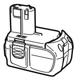
- Battery (BCL1430, EB14B, EBM1830, EB1820L)

EBM1830
It may be convenient to prepare some extra batteries.
2. Tool and adapter
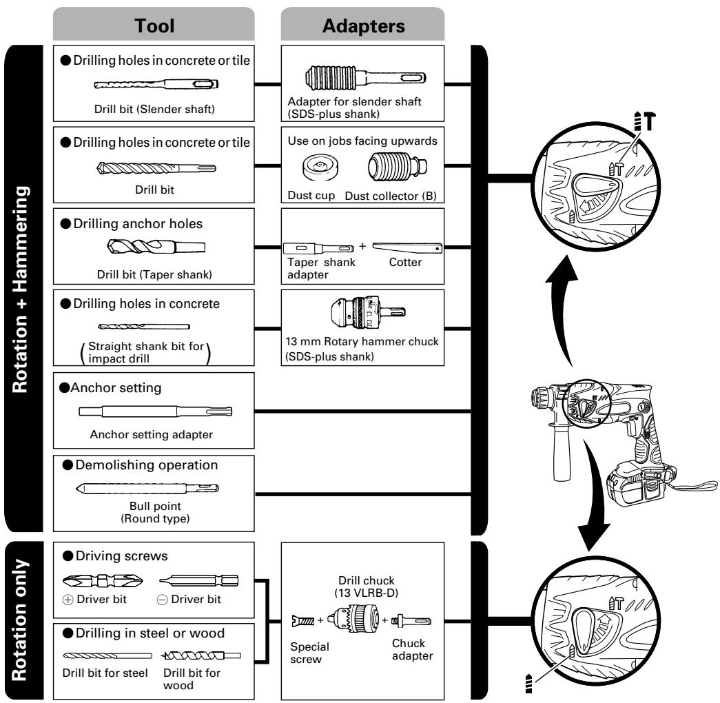
- Drilling holes in concrete or tile
| Drill bit (slender shaft) | ||
| Outer dia. | Overall length | Effective length |
| 3.4 mm | 90 mm | 45 mm |
| 3.5 mm | ||
| SDS-plus Drill bit | ||
| Outer dia. | Overall length | Effective length |
| 4.0 mm | 110 mm | 50 mm |
| 5.0 mm | 110 mm | 50 mm |
| 160 mm | 100 mm | |
| 5.5 mm | 110 mm | 50 mm |
| 6.5 mm | 160 mm | 100 mm |
| 7.0 mm | 160 mm | 100 mm |
| 8.0 mm | 160 mm | 100 mm |
| 8.5 mm | 160 mm | 100 mm |
| 9.0 mm | 160 mm | 100 mm |
| 12.0 mm | 166 mm | 100 mm |
| 260 mm | 200 mm | |
| 12.7 mm | 166 mm | 100 mm |
| 14.0 mm | 166 mm | 100 mm |
| 15.0 mm | 166 mm | 100 mm |
| 16.0 mm | 166 mm | 100 mm |
| 260 mm | 200 mm | |
Drilling anchor holes
| Taper shank adapter |
| Taper mode |
| Morse taper No.1 |
| A-Taper |
| B-taper |
Anchor setting
| Anchor setting adapter Anchor size |
| W 1/4" |
| W 5/16" |
| W 3/8" |
Optional accessories are subject to change without notice.
APPLICATIONS
Rotation and hammering function
Drilling anchor holes
Drilling holes in concrete
Drilling holes in tile
Rotation only function
Drilling in steel or wood (with optional accessories
- Tightening machine screws, wood screws (with optional accessories)
BATTERY REMOVAL/INSTALLATION
1. Battery removal
Hold the handle tightly and push the battery latches (2 pcs.) to remove the battery (see Figs. 1 and 2).
CAUTION:
Never short-circuit the battery.
2. Battery installation
Insert the battery while observing its polarities. (See Fig. 2)
CHARGING
Before using the power tool, charge the battery as follows.
- Connect the charger's power cord to a receptacle. When the power cord is connected, the charger's pilot lamp will blink in red. (At 1-second intervals).
2. Insert the battery into the charger.
Insert the battery firmly, until it contacts the bottom of the charger compartment.
CAUTION:
- If the battery is inserted in the reverse direction, not only recharging will become impossible, but it may also cause problems in the charger such as deformed recharging terminal.
3. Charging
When inserting a battery in the charger, charging will commence and the pilot lamp will light continuously in red.
When the battery becomes fully recharged, the pilot lamp will blink in red. (At 1-second intervals.) (See Table 1)
(1) Pilot lamp indication
The indications of the pilot lamp will be as shown in Table 1, according to the condition of the charger or the rechargeable battery.
Table 1
| Indications of the lamps | |||
| Before charging | Blinks (RED) | Lights for 0.5 seconds. Does not light for 0.5 seconds. (off for 0.5 seconds) | |
| While charging | Lights (RED) | Lights continuously | |
| Charging complete | Blinks (RED) | Lights for 0.5 seconds. Does not light for 0.5 seconds. (off for 0.5 seconds) | |
| Charging impossible | Flickers (RED) | Lights for 0.1 seconds. Does not light for 0.1 seconds. (off for 0.1 seconds) | Malfunction in the battery or the charger. |
| Overheat standby | Lights (GREEN) | Lights continuously | Battery overheated. Unable to charge (Charging will commence when battery cools). |
NOTE: When standby for cooling battery, UC18YRL cools the overheated battery by cooling fan.
(2) Regarding the temperatures of the rechargeable battery.
The temperatures for rechargeable batteries are as shown in the table 2, and batteries that have become hot should be cooled for a while before being recharged.
Table 2 Recharging ranges of batteries
| Charger Rechargeable batteries | UC18YRL | UC18YG |
| BCL1430, EBM1830 | 0°C – 50°C | x |
| EB14B, EB1820L | x | -5°C – 60°C |
-
Disconnect the charger's power cord from the receptacle.
-
Hold the charger firmly and pull out the battery. NOTE:
After operation, pull out batteries from the charger first, and then keep the batteries properly.
CAUTION:
If the battery is charged while it is heated because it has been left for a long time in a location subject to direct sunlight or because the battery has just been used, the pilot lamp of the charger lights up green. In such a case, first let the battery cool, then start charging.
- When the pilot lamp flickers in red (at 0.2-second intervals), check for and take out any foreign objects in the charger's battery installation hole. If there are no foreign objects, it is probable that the battery or charger is malfunctioning. Take it to your authorized Service Center.
Since the built-in micro computer takes about 3 seconds to confirm that the battery being charged with the charger is taken out, wait for a minimum of 3 seconds before reinserting it to continue charging. If the battery is reinserted within 3 seconds, the battery may not be properly charged.
Regarding electric discharge in case of new batteries, etc.
As the internal chemical substance of new batteries and batteries that have not been used for an extended period is not activated, the electric discharge might be low when using them the first and second time. This is a temporary phenomenon, and normal time required for recharging will be restored by recharging the batteries 2-3 times.
How to make the batteries perform longer
(1) Recharge the batteries before they become completely exhausted.
When you feel that the power of the tool becomes weaker, stop using the tool and recharge its battery. If you continue to use the tool and exhaust the electric current, the battery may be damaged and its life will become shorter.
(2) Avoid recharging at high temperatures.
A rechargeable battery will be hot immediately after use. If such a battery is recharged immediately after use, its internal chemical substance will deteriorate, and the battery life will be shortened. Leave the battery and recharge it after it has cooled for a while.
PRIOR TO OPERATION
1. Mounting the drill bit (Fig. 4, 5)
CAUTION:
To prevent accidents, make sure to turn the switch off.
NOTE:
When using tools such as drill bits, etc., make sure to use the genuine parts designated by our company.
(1) Clean the shank portion of the drill bit.
(2) Insert the drill bit in a twisting manner into the tool holder until it latches itself. (Fig. 4)
The grip need not be adjusted during bit installation.
(3) Check the latching by pulling on the drill bit.
(4) To remove the drill bit, fully pull the grip in the direction of the arrow and pull out the drill bit.
- Confirm that the battery is mounted correctly.
- Installation of dust cup or dust collector (B) (Optional accessories) (Fig. 6, Fig. 7)
When using a rotary hammer for upward drilling operations attach a dust cup or a dust collector (B) to collect dust or particles for easy operation.
Installing the dust cup
Use the dust cup by attaching to the drill bit as shown in Fig. 6.
When using a bit which has big diameter, enlarge the center hole of the dust cup with this rotary hammer.
Installing dust collector (B)
When using dust collector (B), insert dust collector (B) from the tip of the bit by aligning it to the groove on the grip. (Fig. 7)
CAUTION:
The dust cup and dust collector (B) are for exclusive use of concrete drilling work. Do not use them for wood or metal drilling work.
Insert dust collector (B) completely into the chuck part of the main unit.
When turning the rotary hammer on while dust collector (B) is detached from a concrete surface, dust collector (B) will rotate together with the drill bit. Make sure to turn on the switch after pressing dust cup on the concrete surface. When using dust collector (B) attached to a drill bit that has more than 190mm of overall length, dust collector (B) cannot touch the concrete surface and will rotate. Therefore, please use dust collector (B) by attaching to drill bits which have 166mm , 160mm , and 110mm overall length.
- Dump particles after every two or three holes when drilling.
Please replace the drill bit after removing dust collector (B).
4. Selecting the driver bit
Screw heads or bits will be damaged unless a bit appropriate for the screw diameter is employed to drive in the screws.
5. Confirm the direction of bit rotation (Fig. 8)
The bit rotates clockwise (viewed from the rear side) by pushing the R-side of the push button. The L-side of the push button is pushed to turn the bit counterclockwise. (See Fig. 8) (The ) and marks are provided on the body.)
CAUTION:
The push button cannot be switched while the power tool is turning. To switch the push button, stop the power tool, then set the push button.
6. Continuous drilling
The number of holes that can be drilled in concrete after one recharge is shown in Table 3.
Table 3
- Use an adapter for a small diameter bit.
These data are for the referential values. The number of holes that can be drilled varies according to the sharpness of the used bit or the conditions of the concrete being drilled.
CAUTION:
When using this unit continuously, the unit may overheat, leading to damage in the motor and switch. Please leave it without using it for approximately 15 minutes.
HOW TO USE
CAUTION:
- When using the light equipped hook, pay sufficient attention so that the main equipment does not fall. If the tool falls, there is a risk of accident.
Do not attach the tip tool except phillips bit to the tool main unit when carrying the tool main unit with the light equipped hook suspended from a waist belt.
Injury may result if you carry the equipment suspended from the waist belt with sharp tipped components such as drill bit attached.
1. Using the light equipped hook
The light equipped hook can be installed on the right or left side and the angle can be adjusted in 5 steps between 0^ and 80^ .
(1) Operating the hook
(a) Pull out the hook toward you in the direction of arrow (A) and turn in the direction of arrow (B). (Fig. 9)
(b) The angle can be adjusted in 5 steps (0^,20^ 40^,60^,80^) Adjust the angle of the hook to the desired position for use.
(2) Switching the hook position
CAUTION:
Incomplete installation of the hook may result in bodily injury when used.
(a) Securely hold the main unit and remove the screw using a slotted head screwdriver or a coin. (Fig. 10)
(b) Remove the hook and spring. (Fig. 11)
(c) Install the hook and spring on the other side and securely fasten with screw. (Fig. 12)
NOTE:
Pay attention to the spring orientation. Install the spring with larger diameter away from you. (Fig. 12)
(3) Using as an auxiliary light
(a) Press the switch to turn off the light.
If forgotten, the light will turn off automatically after 15 minutes.
(b) The direction of the light can be adjusted within the range of hook positions 1 - 5. (Fig. 13)
Lighting time
AAAA manganese batteries: approx. 15 hrs.
AAAA alkali batteries: approx. 30 hrs.
CAUTION:
Do not look directly into the light.
Such actions could result in eye injury.
(4) Replacing the batteries
(a) Loosen the hook screw with a phillips-head screwdriver (No. 1). (Fig. 14)
Remove the hook cover by pushing in the direction of the arrow. (Fig. 15)
(b) Remove the old batteries and insert the new batteries. Align with the hook indications and position the plus (+) and minus (-) terminals correctly. (Fig. 16)
(c) Align the indentation in the hook main body with the protuberance of the hook cover, press the hook cover in the direction opposite to that of the arrow shown in Fig. 15 and then tighten the screw.
Use commercially available AAAA batteries (1.5 V).
NOTE:
Do not tighten the screw excessively. Such action could strip the screw threads.
CAUTION:
Failure to observe the following can result in battery leakage, rust or malfunction.
Position the plus (+) and minus (-) terminals correctly.
Replace both batteries at the same time. Do not mix old and new batteries.
Remove exhausted batteries from the hook immediately.
Do not discard batteries together with normal trash and do not throw batteries into fire.
-
Store batteries out of the reach of children.
-
Use batteries correctly in accordance with the battery specifications and indications.
2. Switch operation
- When the switch trigger is depressed, the tool rotates. When the switch trigger is released, the tool stops.
The rotational speed of the rotary hammer can be controlled by varying the amount that the switch trigger is pulled. Speed is low when the switch trigger is pulled slightly and increases as the switch trigger is pulled more.
- When releasing the switch trigger, the brake will be applied for immediate stopping.
3. Rotation + Hammering
Turn the change lever fully in the direction of the "T" mark to set "rotation + hammering".
(1) Mount the drill bit.
(2) Pull the trigger switch after applying the drill bit tip to the drilling position. (Fig. 17)
(3) Pushing the rotary hammer forcibly is not necessary at all. Pushing slightly so that drill dust comes out gradually is just sufficient.
CAUTION:
When the drill bit touches construction iron bar, the bit will stop immediately and the rotary hammer will react to revolve. Therefore please grip the side handle and handle tightly as shown in Fig. 18.
4. Rotation only
Turn the change lever fully in the direction of the "mark to set "rotation only". (Fig. 17)
To drill a wood or metal material using the optional drill chuck and chuck adapter, proceed as follows. Installing drill chuck and chuck adapter: (Fig. 19)
(1) Attach the drill chuck to the chuck adaptor.
(2) The part of the SDS-plus shank is the same as the drill bit. Therefore, refer to the item of "Mounting the drill bit" for attaching it.
CAUTION:
Application of force more than necessary will not only expedite work at all, but will deteriorate the tip edge of the drill bit and reduce the service life of the rotary hammer in addition.
Drill bit may snap off while withdrawing the rotary hammer from the drilled hole. For withdrawing, it is important to use a pushing motion.
Do not attempt to use the rotary hammer in the rotation and striking mode with the drill chuck and chuck adapter attached. This would seriously shorten the service life of every component of the machine.
5. When driving wood screws (Fig. 20)
(1) Selecting a suitable driver bit
Employ plus-head screws, if possible, since the driver bit easily slips off the heads of slotted-head screws.
(2) Tightening wood screws
Prior to tightening wood screws, make pilot holes suitable for them in the wooden board. Apply the bit to the screw head grooves and gently drive the screws in the holes.
CAUTION:
Exercise care in preparing a pilot hole suitable for the wood screw taking the hardness of the wood into consideration. Should the hole be excessively small or shallow, requiring much power to drive the screw into it, the thread of the wood screw may sometimes be damaged.
6. Using depth gauge (Fig. 21)
(1) Loosen the knob on the side handle, and insert the depth gauge into the mounting hole on the side handle.
(2) Adjust the depth gauge position according to the depth of the hole and tighten the knob bolt securely.
7. How to use the drill bit (taper shank) and the taper shank adapter
(1) Mount the taper shank adapter to the rotary hammer. (Fig. 22)
(2) Mount the drill bit (taper shank) to the taper shank adapter. (Fig. 22)
(3) Turn the switch ON, and drill a hole to prescribed depth.
(4) To remove the drill bit (taper shank), insert the cotter into the slot of the taper shank adapter and strike the head of the cotter with a hammer supporting on the rest. (Fig. 23)
8. Switching between the "SAVE" and the "POWER" modes
The hammering force of the hammer can be increased or decreased to conform with intended usage, by operating the shift knob as per Fig. 24. Adjust the force to match the usage intended.
(1) "SAVE" mode ... decreased hammering force This can prevent thin drill bits which are less than 4.3mm in diameter, from being bent or broken.
(2) "POWER" mode ... increased hammering force
This can be used to speedily and efficiently drill holes when the drill bits which are being used are greater than 4mm in diameter.
This can be used to drill holes into wood or metal. CAUTION:
Do not drill holes in wood with the "SAVE" mode. There is a likelihood that the motor will burn out because it can easily lock up due to the low power.
LUBRICATION
Low viscosity grease is applied to this rotary hammer so that it can be used for a long period without replacing the grease. Please contact the nearest service center for grease replacement when any grease is leaking form loosened screw.
Further use of the rotary hammer despite the grease shortage causes damage to reduce the service life.
CAUTION:
A specific grease (FG-6A) is used with this machine, therefore, the normal performance of the machine may be badly affected by use of different grease. Please be sure to let one of our service centers to undertake replacement of the grease.
MAINTENANCE AND INSPECTION
1. Inspecting the tool
Since use of a dull tool will degrade efficiency and cause possible motor malfunction, sharpen or replace the tool as soon as abrasion is noted.
2. Inspecting the mounting screws
Regularly inspect all mounting screws and ensure that they are properly tightened. Should any of the screws be loose, retighten them immediately. Failure to do so could result in serious hazard.
3. Maintenance of the motor
The motor unit winding is the very "heart" of the power tool. Exercise due care to ensure the winding does not become damaged and/or wet with oil or water.
4. Inspecting the carbon brushes (Fig. 25)
The motor employs carbon brushes which are consumable parts. Since and excessively worn carbon brush can result in motor trouble, replace the carbon brush with new ones when it becomes worn to or near the "wear limit". In addition, always keep carbon brushes clean and ensure that they slide freely within the brush holders.
NOTE:
When replacing the carbon brush with a new one, be sure to use the Hitachi Carbon Brush Code No. 328481.
5. Replacing carbon brushes
Take out the carbon brush by first removing the brush cap and then hooking the protrusion of the carbon brush with a slotted head screw driver, etc., as shown in Fig. 27.
When installing the carbon brush, choose the direction so that the nail of the carbon brush agrees with the contact portion outside the brush tube. Then push it in with a finger as illustrated in Fig. 28. Lastly, install the brush cap.
CAUTION:
Be absolutely sure to insert the nail of the carbon brush into the contact portion outside the brush tube. (You can insert whichever one of the two nails provided.)
Caution must be exercised since any error in this operation can result in the deformed nail of the carbon brush and may cause motor trouble at an early stage.
6. Cleaning on the outside
When the power tool is stained, wipe with a soft dry cloth or a cloth moistened with soapy water. Do not use chloric solvents, gasoline or paint thinner, as they melt plastics.
7. Storage
Store the power tool in a place in which the temperature is less than 40^ and out of reach of children.
8. Service parts list
CAUTION
Repair, modification and inspection of Hitachi Power Tools must be carried out by a Hitachi Authorized Service Center.
This Parts List will be helpful if presented with the tool to the Hitachi Authorized Service Center when requesting repair or other maintenance.
In the operation and maintenance of power tools, the safety regulations and standards prescribed in each country must be observed.
MODIFICATIONS
Hitachi Power Tools are constantly being improved and modified to incorporate the latest technological advancements.
Accordingly, some parts may be changed without prior notice.
GUARANTEE
We guarantee Hitachi Power Tools in accordance with statutory/country specific regulation. This guarantee does not cover defects or damage due to misuse, abuse, or normal wear and tear. In case of complaint, please send the Power Tool, undismantled, with the GUARANTEE CERTIFICATE found at the end of this Handling instruction, to a Hitachi Authorized Service Center.
NOTE:
Due to HITACHI's continuing program of research and development, the specifications herein are subject to change without prior notice.
IMPORTANT:
Correct connections of the plug
The wires of the mains lead are coloured in accordance with the following code:
Blue: -Neutral
Brown: -Live
As the colours of the wires in the mains lead of this tool may not correspond with the coloured markings identifying the terminals in your plug proceed as follows: The wire coloured blue must be connected to the terminal marked with the letter N or coloured black.
The wire coloured brown must be connected to the terminal marked with the letter L or coloured red.
Neither core must be connected to the earth terminal.
NOTE:
This requirement is provided according to BRITISH STANDARD 2769:1984.
Therefore, the letter code and colour code may not be applicable to other markers except United Kingdom.
Information concerning airborne noise and vibration
The measured values were determined according to EN60745 and declared in accordance with ISO 4871.
[DH14DL, DH14DMR]
Measured A-weighted sound power level: 96 dB (A)
Measured A-weighted sound pressure level: 85 dB (A)
Uncertainty KpA: 3 dB (A).
Wear ear protection.
Vibration total values (triax vector sum) determined according to EN60745.
Hammer drilling into concrete:
Vibration emission value HD = 8.6m / s^2
Uncertainty K = 1.5m / s^2
[DH18DL, DH18DMR]
Measured A-weighted sound power level: 98 dB (A)
Measured A-weighted sound pressure level: 87 dB (A)
Uncertainty KpA: 3 dB (A).
Wear ear protection.
Vibration total values (triax vector sum) determined according to EN60745.
Hammer drilling into concrete:
Vibration emission value h , HD = 9.8~m / s^2
Uncertainty K = 1.5m / s^2
WARNING
The vibration emission value during actual use of the power tool can differ from the declared value depending on the ways in which the tool is used.
To identify the safety measures to protect the operator that are based on an estimation of exposure in the actual conditions of use (taking account of all parts of the operating cycle such as the times when the tool is switched off and when it is running idle in addition to the trigger time).
- Battery (BCL1430, EB14B, EBM1830, EB1820L)

EBM1830
ACCESSIONS STANDARDS
- Batterie (BCL1430, EB14B, EBM1830, EB1820L)
EBM1830
| Chargeur Batteries rechargeables | UC18YRL | UC18YG |
| BCL1430, EBM1830 | 0°C – 50°C | x |
| EB14B, EB1820L | x | -5°C – 60°C |
- Batteria (BCL1430, EB14B, EBM1830, EB1820L)

EBM1830
- Bateria (BCL1430, EB14B, EBM1830, EB1820L)
EBM1830
- Bateria (BCL1430, EB14B, EBM1830, EB1820L)
EBM1830
- Mnatapia (BCL1430, EB14B, EBM1830, EB1820L)
EBM1830
Mnopei va eivai Boaiko va etoumaeTe eepiec e npooetec natapiec.
2. Epyaieio kai npoapouyea
I a I p I N Tou n Iaaikiod
H M E I H
Only for EU countries
Do not dispose of electric tools together with household waste material!
In observance of European Directive 2002/96/EC on waste electrical and electronic equipment and its implementation in accordance with national law, electric tools that have reached the end of their life must be collected separately and returned to an environmentally compatible recycling facility.
Deutsch
Nur für EU-Länder
Móvo yia tic xwpec tnc EE
Mny nTATE ta nEeKtpiKa epyaIia oToV kaO oikiakwv anoppmuatWv!
Zuupwva eTnv Eupwnk obnyia 2002/96/EK npi Nktpikov kai Nktpovikov oukeuw kai Tnv Evomega twn TcO OeVko dkaio, ta Nktpika epyalea npenei va oulambdaoyvai Exwpiotka kai va eniopepovtal ia vakukawon me TpOIO pIiko npoc to PJIaALov.
| English | Nederlandsl | ||
| EC DECLARATION OF CONFORMITYWe declare under our sole responsibility that this product is in conformity with standards EN60745, EN55014 and EN61000 in accordance with Council Directives 73/23/EEC, 89/336/EEC and 98/37/EC.This declaration is applicable to the product affixed CE marking. | EC VERKLARING VAN CONFORMITEWij verklaren onder eigen verantwoordelijkheid dat dit product conform de richtlijnen EN60745, EN55014 en EN61000 voldoet aan de eisen van EEG Bepalingen 73/23/EEG, 89/336/EEG en 98/37/EC.Deze verklaring is van toepassing op Produkten voorzien van de CE-markeringen. | ||
| Deutsch | Espanol | ||
| ERKLÄRUNG ZUR KONFORMITÄT MIT CE-REGELNWir erklärren in alleiniger Verantwortung, dass diese Produkt den Standards EN60745, EN55014 und EN61000 in Übereinstimmung mit den Direktiven des Europarates 73/23/EWG, 89/336/EWG und 98/37/CEentspricht.Diese Erklärung gilt für Produkte, die die CE-Markierung tragen. | DECLARACION DE CONFORMIDAD DE LA CEDeclaramos bajo unsere una responsabilitad que este producto cumple las normas EN60745, EN55014 y EN61000 según indican las Directivas del Consejo 73/23/CEE, 89/336/CEE y 98/37/CE.Esta declaración se aplica a los products con marcas de la CE. | ||
| Français | Portugués | ||
| DECLARATION DE CONFORMITE CENous déclarons sous notre seule et entière responsabilité que ce produit est conforme aux normes EN60745, EN55014 et EN61000, en accord avec les Directives 73/23/CEE, 89/336/CEE et 98/37/CE du Conseil.Cette déclaration s'applique aux produits désignés CE. | DECLARÇÃO DE CONFORMIDADE CEDeclaramos, sob{nossa uncona e inteira responsabilitadque este produit está de acordo com as normas EN60745, EN55014 e EN61000 em conformidade comas Direcrivas 73/23/CEE, 89/336/CEE e 98/37/CE do Conselho.Esta declaresao se aplica aos produits designados CE. | ||
| Italiano | Ελληνικα | ||
| DICHiarAZIONE DI CONFORMITÀ CESi dichiarara sotto notre responsabilità che"This prodotto è conforme agli standard EN60745, EN55014e EN61000 conformamente alle direttive 73/23/CEE, 89/336/CEE e 98/37/CE del Concilio.Questa dichiarazione è applicabile ai prodotti cui sono applicati i marchi CE. | EK ΔΗΛΟΥΗ ENAPMONIΙΜΟYΔηλώνουμε με απόλυτη πιεύθυνότητα ὄτι autο το προίν εἰναι εναρμονιαμένον με τα πρότινα EN60745,EN55014 και EN61000 σύμφωνα με τις Εθήγίες tou Σμβουλίου 73/23/EOK, 89/336/EOK και 98/37/EE.Autήη δήλωση σαχύει στο προίν με το σημάδι EC. | ||
| Representative office in EuropeHitachi Power Tools Europe GmbHSiemensring 34, 47877 Willich 1, F. R. GermanyHead office in JapanHitachi Koki Co., Ltd.Shinagawa Intercity Tower A, 15-1, Konan 2-chome,Minato-ku, Tokyo, Japan | CE30.1.2007K. KatoBoard Director | ||