
MX 125 - Motorcycle APRILIA - Free user manual and instructions
Find the device manual for free MX 125 APRILIA in PDF.
| Product type | Motorcycle |
| Brand | APRILIA |
| Model | MX 125 |
| Category | Supermoto / Enduro |
| Engine | Single-cylinder 4-stroke, liquid cooling |
| Displacement | 124.8 cc |
| Max power | 11 kW (15 hp) at 9,000 rpm |
| Max torque | 12 Nm at 7,500 rpm |
| Fuel system | Carburetor or injection (depending on version) |
| Transmission | 6-speed gearbox, chain |
| Front brake | Single disc Ø 300 mm, 2-piston caliper |
| Rear brake | Single disc Ø 220 mm, 1-piston caliper |
| Front suspension | Inverted fork Ø 41 mm, travel 250 mm |
| Rear suspension | Mono-shock, travel 280 mm |
| Front tire | 100/80-17 |
| Rear tire | 130/70-17 |
| Dimensions (L × W × H) | 2,060 × 820 × 1,180 mm |
| Seat height | 880 mm |
| Wheelbase | 1,400 mm |
| Dry weight | 118 kg |
| Fuel tank capacity | 7 L (including reserve 1.5 L) |
| Average fuel consumption | 3.5 L/100 km |
| Battery | 12 V, 7 Ah |
| Lighting | Halogen headlight H4 12V 55/60W |
Frequently Asked Questions - MX 125 APRILIA
User questions about MX 125 APRILIA
0 question about this device. Answer the ones you know or ask your own.
Ask a new question about this device
Download the instructions for your Motorcycle in PDF format for free! Find your manual MX 125 - APRILIA and take your electronic device back in hand. On this page are published all the documents necessary for the use of your device. MX 125 by APRILIA.
USER MANUAL MX 125 APRILIA
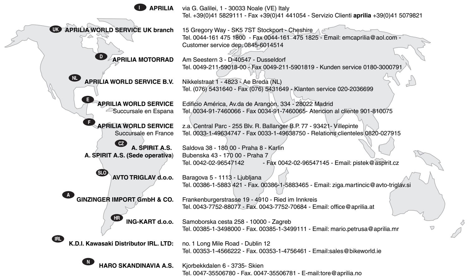
via G. Galilei, 1 - 30033 Noale (VE) - Italy
Tel. +39 - (0)41 58 29 111
Fax +39-(0)41 44 10 54
www.aprilia.com
No. 281 Jungshing North Street - Sanchung City - 241 - Taipei
Tel. 00886-2-85111156 - Fax: 00886 2 85111148 - Email: taiwan.eisyu @ msa.hinet.net

AL-RADWAN INTERNATIONAL GROUP
Block 1, Street 13, Plot 107 45703 - Shuwaikh Industrial
Tel. 00965-4828072 - Fax. 00965-4828073 - Email: zed@zedmotorz.com

ACCESS INTERNATIONAL FOR TRADING SARL.
Diamond Tower, 10th Floor P.O.B. 13 - Verdun, near Mandarine Beirut
Tel. 00961-1797333 - Fax: 00961-1798333 - Email: access_in@ hotmail.com

PT. MOTOR MEGA PERFORMA
MHNYMATA AΣΦΑΛΕΙΑΣ 2
TEXNIKEI ΠΛHPOΦΟPIEΣ 2
\PPOEI ONOIH E - POΦYλA E - POEI ONOIH E ΓENIKA 2
NEPIEXOMENA 4
K O P E N A 38
ΦPENO EMПОБ 39
ΦPENO ΠIΩ 40
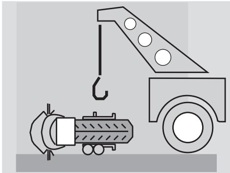
ToTIOeTeIaTeToDikukLooOToSTavT.
KINΔYNOΣ
Aoyw Tou yapouc KAI Tou oykou Tou
dikuklou, n Evepyeia Tou akoaloue i
aataie Tnv ETEmuaon Evoc dutepuo
atou. PPOxwpnote TPOOEKTiKa KAI
Bebaiowte OTI MTOpeite va Kpatnoete
to yapoc Tou dikuklou.
PPOsOXH
KATEBACOTENVALUOIDA6OTNVEGWTEPIKNTLEUPATNSOoovTWTNCKOPwvac7.

KINΔYNOΣ
Mny bace ta daxtuia oac avaeo aTnv aluoia kai otny oobvtwn Kopwa.
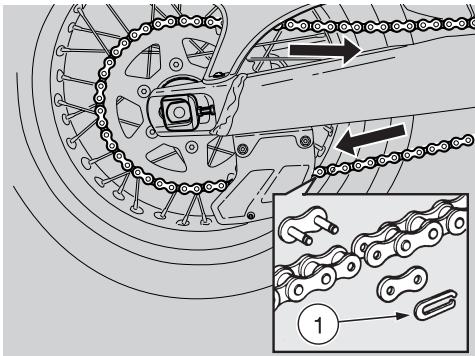
Metakivnote eVTEwS mTPOoTa Tov TPOXo.Apaieote Tnv aluoiOa aTIO Tnv EIAW PLEUPA TEPiOTpeovotac, Oe AVIeTN FOpA aTIO TNV KAVOVIK NopA KIVNOs,Tov Tiaw TPOxO.

PPOZOXH
Kata nTv eTavaovapuOlynon, bAte Tnv aUoia aTTO nTv kATw PLEupa TEPiOTpeovtac Tov Tiow TPOXo TPOCS TNV KATEUBVOn KAVOVIKns TOpEiaC.
三 KAI aqaipéoTe TO TnAiaTou TPOXou (3) KAI Tn Poδελa (8).

PPOZOXH
Tia va dieukoluveTe Tnv Eaywyn Tou TEipou, ONKwote Eaqpa Tov Tpoxó.
KpatnoTe Tov Tiow Tpoxo Kai TpaBnEte To Xepi Tov Tpiopo Tou Tpoxou (9).

PPOZOXH
To apioTepo diaxwpiotiko (10) kai to
dei diaxwpiotiko (11) npapaevouv otic
avtioixes utooxcs Tou tpoxou. Eav
byouv ano tn 0eon touc
etavatoTOnOeTnoTe ta kataaannawc
(βaETE ENANAZYNAPMOANOH).
TpaBnTcEgWTOVtpoXoATNOVTNtiow TTLEUPaTou TnpouvIOU, TPOeXovTACVa ByeO OioKoC TOU φpevou AIO TOn Daykava.

KINΔYNOΣ
Mny nntoTo moxlo Tou Niow
pveou meta TnV Eaywyn Tou Tpoxou,
diawopetikato EboLakni Gaykavac
mtopei va Byei an tov unOboxn Tou,
Ppokalwvtac diappon Tou Uypou
ppevw. autnv Tnv Pepinttwon
atueuthetaeite oEvav Enionpo
AvntpóωTTO ts aprilia, o otioo 8α φρονtioεI VA KAVI T N OUVtnpnO.

PPOZOXH
ELeyTe Tn θeON Twv diaxwpiotikuv (10) kai (11) ia va μTOpεeTE va ta επavaouvapμooyσeTE σωτα.
ByaIeTo aipTepeiawpiotiko (10).
ByaTeTo 0iaxwiotiko (11).
Kata nV eTavatoToToEtno:
paosaperte eaaopwTIGeowtepiKcS UTOOoxEc TNS PAnmuNtou TPOXOU.
TOnTOeTnOte Ta diaxwpiOTiKa (10) (11) Tn TEyAulTepn DIAEETPOC TPOC TNV E5WTEPIKn TAAUPa TOU OIKkLou.
EttaleiTE OMOIOOPpa mia iKpn TTOOOTnTa ypaoou OTOV TEIPO TO TPOXOU.

KINΔYNOΣ
MetaTnV Etnavacovapuoloyon,
PntnoTe EtnaveiIhmuEva To moXto Tou
Piow Ppevou Kai ElambdaEYsTe Tn Owotn
Aeioupyia Tou oUOTnmuTOC Ppevwv.
EeYxos Kevtpapiaatoc tpoxou.
Sigmaatai va ateuthetaite yia eeyxo otis potncs ouoqicns, oto kevtpapioka kai otn zuyootatou troxou oe evav Eianpo Avtinppoosntnags aprilia ia va aonopuyete tuxov npoBnaTPOU Oa mnpouoav va npokaloeouv oobapec zmuie c 0a cak/ no ae alouc. Eeyte to TeVTwma ncs aluoiidac.
AAYIAMA METAOESH
Aiaaote npooektikc otn oEλ.55 (SYNTHPHsH).
PYOMIISH IPOΦOPTIeH ΠIeΩ AMOPTIeP
Hpuoian otavtapou eptpocnipouviou exyivei e Tetoiv TpTO wote va ikavotoiie tis ouvthenc oynnncs peikn kai evaal taxutnta, too e miKpo qoptio 0oo kai e PAnpeqoptio.
PYOMISH XEIPISTHPIOY EKKINHSE ME KPYO (N)
Aiaaote npooektikc otn oEλ.55 (SYNTHPHsH).
To 1aiko diakevo tou xeiipotnpiou Ekkivnns e Kpu Tpente va evai 2x3mm. Ia tn pthetai:
H AEA THS TEXNIKHES YIIOESTHPIEH
aprilia
Xapn otuuvexn texvikn katapton kai ota poypauata eikngs ektaideuans naww o ta troiovta aprilia, mvo oi uxavko tou Etniou Aiktuou aprilia ywwipizouv kaiauto to dikuklo kai diaetouv tov eiko attaioevo eoioyia tn owtn ekteean eTnebetaeew ouvtnponc kai tiokeunc.
H aioiotia tou oxnatoe xaptatai kai ato tn unxavik kataoaon tou idou. O eeyxos niv ao tnv obynon, n taektk ouvtnponkai npan yvnoiw avtaalaktkow aprilla anoteauov ouoiotaikoic npayovtec!
Tia nnpopopiec oxetikac e to Etnioo AvntpooTo kai/n to Tnoiotepo Kevtpo TeviKc Ytoaoueute to Xpuo Ondyo havte aantueiac avznton oTo xaptn Tou uTAPxE oTo Etnioo loTOxwpo:
www.aprilia.com
Móvo éav zntáte Fvnaia Avtaaaktiká aprilia 0e xete eva pioov melaetnevo kai dokipaaevo non aTn qaoan oxediaou. Ta Fvnaia Avtaaaktiká aprilia utokevtai ouvexwC eDiaikacicELeyXou TIOIOTAC, yia va eaoqalioti n agiotia kai n diapkeia touc oTO xpOvo.

MOTOMAX MOTORLU ARACLAR SAN.VETIC.A.S.
Kore Sehitleri Cad. No. 42 - 80300 - Zincirlikuyu - Istanbul
Tel. 0090-212-3360058 - Fax. 0090-212-3360057 - Email:sule@interline.com.tr

MILLE MOTOR KFT. (sede operativa)
Hold utca 23 - H-1054 - Budapest
Tel. 0036-1-3329938 - Fax. 0036-1-2693044 - Email: Zsoldos.lajos@elender.hu

MILFA IMPORTACAO EXPORTACAO LDA.
Av. Da Republica 692 - 4450 - Matosinhos
Tel. 00351-229382450 - Fax. 00351-229371305 - Email: milfa@milfa.pt

APRILIA HELLAS
Rizareiou 4 - 15233 - Halandri
Tel. 0030-210-6898290 - Fax. 0030-210-6898056 - Email: aprilia@otermail.gr

MOHAG A.G.
Bernerstrasse Nord 202 - 8064 - Zurigo
Tel. 0041-1-4348686 - Fax 0041-1-434 8606 - Email: agonser@mohag.ch

N.V./S.A. RAD
Landegemstraat 4 - Industriegebied - B-9031 - Drongen-Baarle Tel. 0032-9-2829410 - Fax. 0032-9-2810012 - Email: aprilia@rad.be

T.M.P.
Hammervej 32 - 7900 - Nikobing Mors
Tel. 0045-97-722233 - Fax. 0045-97-722143/33 - Email: thomas@aprilia.dk

TUONTINAKKILA OY
P.o.B. 18 - 29250 - Nakkila
Tel. 00358-2-5352500 - Fax. 00358-2-5372793 - Email: satu.saarinen@aprilia.fi

RO GROUP INT.(sede operativa)
Str. Depozitelor 41-43 Jud. Arges - Pitesti
Tel. 0040-248211004 -Fax. 0040-248211004 - Email: marian.ion@rogroup.ro

Z.A.O. ITALMOTO (sede operativa)
Ul. Preobragenskaya 5/7 - 107076 - Mo - Moscow
Tel. 007-095-780 4294 - Fax. 007-095-208 3228 - Email: italmoto@mtu-net.ru

APRILIA U.S.A., INC. (Sede operativa)
109 Smoke Hill Lane Suite 190 - GA 30188 - Woodstock
Tel. 001-770-592-2261 - Fax. 001-770-592-4878

APRILIA JAPAN CORP.
SHINYOKOHAMAMEGURO BLDG. 3-22-5 SHINYOKOHAMA KOUHOKU-KU 222-0033
YOKOHAMA-SHI KANAGAWA (J) -Tel. 0081-454772632 - Fax 0081-454772605 - Email: m-okuyama@apriliajapan.co.jp

JOHN SAMPLE GROUP PTY LTD.
8 Sheridan Close - NSW 2214 - Milperra - Sydney
Tel. 0061-2-97722666 - Fax. 0061-2-97742321 - Email: doreilly@jsg.com.au

No. 281 Jungshing North Street - Sanchung City - 241 - Taipei
Tel. 00886-2-85111156 - Fax. 00886 2 85111148 - Email: taiwan.eisyu@msa.hinet.net

AL-RADWAN INTERNATIONAL GROUP
Block 1, Street 13, Plot 107 45703 - Shuwaikh Industrial
Tel. 00965-4828072 - Fax. 00965-4828073 - Email: zed@zedmotorz.com

ACCESS INTERNATIONAL FOR TRADING SARL.
Diamond Tower, 10th Floor P.O.B. 13 - Verdun, near Mandarine Beirut
Tel. 00961-1797333 - Fax: 00961-1798333 - Email: access_in@ hotmail.com

PT. MOTOR MEGA PERFORMA
First edition: October 2003
Reprint:
Produced and printed by:
DECA s.r.l.
Via Risorgimento, 23/1 - Lugo (RA) - Italia
Tel. +39 - 0545 35235
Fax +39-0545 32844
E-mail: deca@decaweb.it
www.decaweb.it
On behalf of:
aprilia.s.p.a.
via G. Galilei, 1 - 30033 Noale (VE) - Italy
Tel. +39 - (0)41 58 29 111
Fax +39-(0)41 44 10 54
www.aprilia.com
SAFETYWARNINGS
The following precautionary warnings are used throughout this manual in order to convey the following messages:
Safety warning. When you find this symbol on the vehicle or in the manual, be careful to the potential risk of personal injury. Non-compliance with the indications given in the messages preceded by this symbol may result in considerable risks for your and other people's safety and for the vehicle!
WARNING
Indicates a potential hazard which may result in serious injury or even death.
CAUTION
Indicates a potential hazard which may result in minor personal injury or damage to the vehicle.
NOTE The word "NOTE" in this manual precedes important information or instructions.
TECHNICAL INFORMATION
The operations preceded by this symbol must be repeated also on the opposite side of the vehicle.
If not expressly indicated otherwise, for the reassembly of the units repeat the disassembly operations in reverse order.
The terms "right" and "left" are referred to the rider seated on the vehicle in the normal riding position.
WARNING - PRECAUTIONS - GENERAL ADVICE
Before starting the engine, carefully read this manual and in particular the section "SAFE DRIVE".
Your and other people's safety depends not only on your quickness of reflexes and on your agility, but also on what you know about the vehicle, on its efficiency and on your knowledge of the basic information for "SAFE DRIVE". Therefore, get a thorough knowledge of the vehicle, in such a way as to be able to drive in the traffic safely.
NOTE Keep a stock of one bulb per type with the vehicle (see technical data).
NOTE This manual must be considered as an integral part of the vehicle and must always accompany it, even in case of resale.
aprilia has prepared this manual with the maximum attention, in order to supply the user with correct and updated information. However, since aprilia constantly improves the design of its products, there may be slight discrepancies between the characteristics of your vehicle and those described in this manual. For any clarification concerning the information contained in this manual, do not hesitate to contact your aprilia Official Dealer.
For control and repair operations not expressly described in this publication, for the purchase of aprilia genuine spare parts, accessories and other products, as well as for specific advice, contact exclusively aprilia Official Dealers and Service Centers, which guarantee prompt and accurate assistance.
Thank you for choosing aprilia. We wish you a nice ride.
All rights as to electronic storage, reproduction and total or partial adaptation, with any means, are reserved for all Countries.
NOTE In some countries the antipollution and noise regulations in force require periodical inspections.
The user of the vehicle in these countries must:
- contact an aprilia Official Dealer to have the non-homologated components replaced with others homologated for use in the country in question;
- carry out the required periodical inspections.
NOTE Soon after purchasing the vehicle, write down the identification data indicated on the SPARE PARTS IDENTIFICATION LABEL in the table here below. This label is positioned on the frame, under the saddle; to read it, it is necessary to remove the saddle.
| I | UK | A | P | SF | B | D | F | E | GR |
| NL | CH | DK | J | SGP | SLO | IL | ROK | MAL | RCH |
| HR | AUS | USA | BR | RSA | NZ | CDN |
These data indicate:
year of manufacture (Y, 1, 2, ...);
- modification code (A, B, C, ...);
- homologation country (I, UK, A, ...).
and are to be supplied to the aprilia Official Dealer as reference data for the purchase of spare parts or specific accessories of the model you have
acquired.
In this manual the various versions are indicated by the following symbols:
OPT optional
FP Free Power version
VERSION:
PRELIMINARY CHECKING OPERATIONS 47
STARTING 48
DEPARTURE AND DRIVE 50
RUNNING-IN 53
STOPPING 53
PARKING 54
POSITIONING THE VEHICLE
ON THE STAND 54
SUGGESTIONS
TO PREVENT THEFT 54
MAINTENANCE 55
REGULAR SERVICE INTERVALS CHART. 56
IDENTIFICATION DATA 58
REMOVING THE SIDE COVERS. 58
AIR CLEANER 59
CHECKING THE TRANSMISSION OIL LEVEL
AND TOPPING UP 60
CHANGING THE TRANSMISSION OIL 61
FRONT WHEEL 62
REAR WHEEL 64
DRIVE CHAIN 66
INSPECTING THE FRONT AND REAR SUSPENSIONS. 68
REAR SUSPENSION 69
CHECKING AND CLEANING THE TERMINALS 74
REMOVING THE BATTERY 74
CHECKING THE ELECTROLYT ELEVEL 75
RECHARGING THE BATTERY 75
INSTALLING THE BATTERY 75
CHANGING THE FUSES. 76
CHECKING THE SIDE STAND AND THE SAFETY SWITCH 77
CHECKING THE SWITCHES 77
ADJUSTING THE VERTICAL HEADLIGHT BEAM. 78
BULBS. 78
CHANGING THE HEADLIGHT BULBS. 79
CHANGING THE DASHBOARD BULBS 80
CHANGING THE FRONT AND REAR DIRECTION INDICATORS 81
CHANGING THE REAR LIGHT BULB 81
TRANSPORT 82
DRAINING THE FUEL TANK 82
CLEANING 83
LONG PERIODS OF INACTIVITY 84
AFTER A PERIOD OF INACTIVITY 84
TECHNICAL DATA 85
LUBRICANT CHART 88
AUTHORISED DEALERS AND SERVICE CENTRES 89
IMPORTERS 90
IMPORTERS 91
IMPORTERS 92
Importers 93
WIRING DIAGRAM - MX 125. 94
WIRING DIAGRAM KEY-MX 125 95

safe drive
SAFETY RULES
To drive the vehicle it is necessary to be in possession of all the requirements prescribed by law (driving licence, minimum age, psychophysical ability, insurance, state taxes, vehicle registration, number plate, etc.).
Gradually get to know the vehicle by driving it first in areas with low traffic and/or private areas.
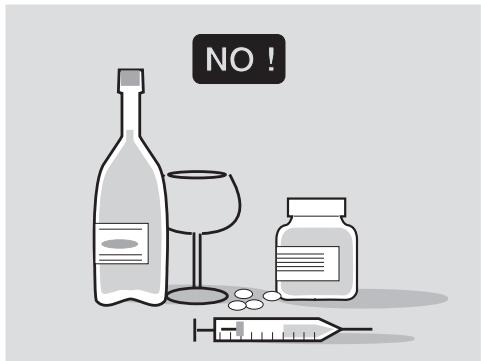
The use of medicines, alcohol and drugs or psychotropic substances notably increases the risk of accidents.
Be sure that you are in good psychophysical conditions and fit for driving and pay particular attention to physical weariness and drowsiness.
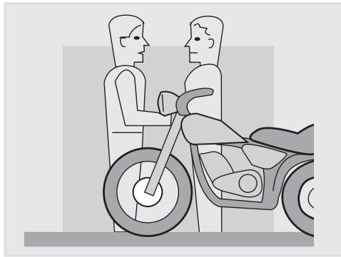
Most road accidents are caused by the driver's lack of experience.
NEVER lend the vehicle to beginners and, in any case, make sure that the driver has all the requirements for driving.
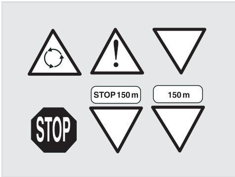
Rigorously observe all road signs and national and local road regulations.
Avoid abrupt movements that can be dangerous for yourself and other people (for example: rearing up on the back wheel, speeding, etc.), and give due consideration to the road surface, visibility and other driving conditions.
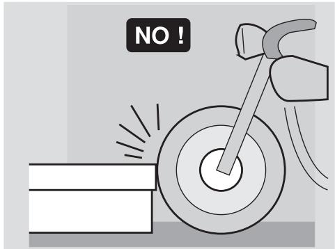
Avoid obstacles that could damage the vehicle or make you lose control.
Avoid riding in the slipstream created by preceding vehicles in order to increase your speed.
WARNING
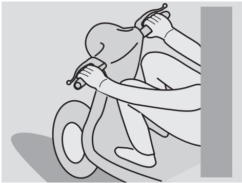
Always drive with both hands on the handlebars and both feet on the footrests (or on the rider's footboards), in the correct driving posture.
Avoid standing up or stretching your limbs while driving.
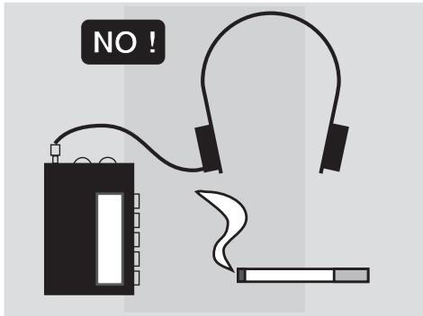
The driver should pay attention and avoid distractions caused by people, things and movements (never smoke, eat, drink, read, etc.) while driving.
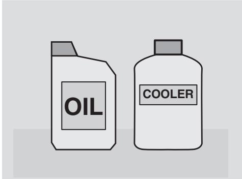
Use only the vehicle's specific fuels and lubricants indicated in the "LUBRICANT CHART"; check the oil, fuel and coolant levels regularly.
If the vehicle has been involved in an accident, make sure that no damage has occurred to the control levers, pipes, wires, braking system and vital parts.
If necessary, have the vehicle inspected by an aprilia Official Dealer, who should carefully check the frame, handlebars, suspensions, safety parts and all the devices that you cannot check by yourself.
Always remember to report any malfunction to the technicians to help them in their work.
Never use the vehicle when the amount of damage it has suffered endangers your safety.

Never change the position, inclination or colour of: number plate, direction indicators, lights and horns.
Any modification of the vehicle will result in the invalidity of the guarantee.
Any modification of the vehicle and/or the removal of original components can compromise vehicle performance levels and safety or even make it illegal.
We recommend respecting all regulations and national and local provisions regarding the equipment of the vehicle.
In particular, avoid all modifications that increase the vehicle's performance levels or alter its original characteristics.
Never race with other vehicles.
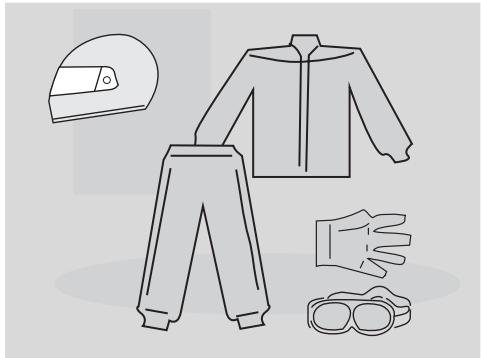
CLOTHING
Before starting, always wear a correctly fastened crash helmet. Make sure that it is homologated, in good shape, of the right size and that the visor is clean.
Wear protective clothing, preferably in light and/or reflecting colours. In this way you will make yourself more visible to the other drivers, thus notably reducing the risk of being knocked down, and you will be more protected in case of fall.
This clothing should be very tight-fitting and fastened at the wrists and ankles. Strings, belts and ties should not be hanging loose; prevent these and other objects from interfering with driving by getting entangled with moving parts or driving mechanisms.
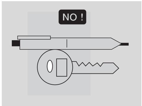
Do not keep objects that can be dangerous in case of fall, for example pointed objects like keys, pens, glass vials etc. in your pockets (the same recommendations also apply to passengers).
ACCESSORIES
The owner of the vehicle is responsible for the choice, installation and use of any accessory.
Avoid installing accessories that cover horns or lights or that could impair their functions, limit the suspension stroke and the steering angle, hamper the operation of the controls and reduce the distance from the ground and the angle of inclination in turns.
Avoid using accessories that hamper access to the controls, since this can prolong reaction times during an emergency.
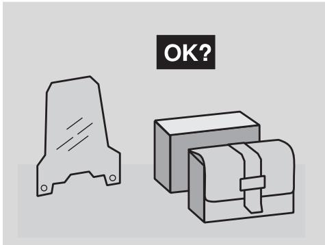
Large fairings and windscreens assembled on the vehicle can produce aerodynamic forces capable of compromising the stability of the vehicle while driving.
Make sure that the equipment is well fastened to the vehicle and not dangerous during driving. Do not install electrical
devices and do not modify those already existing to avoid electrical overloads, because the vehicle could suddenly stop or there could be a dangerous current shortage in the horn and in the lights. aprilia recommends the use of genuine accessories (aprilia genuine accessories).
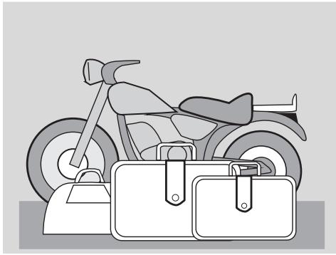
LOAD
Be careful and moderate when loading your luggage. Keep any luggage loaded as close as possible to the centre of the vehicle and distribute the load uniformly on both sides, in order to reduce imbalance to the minimum. Furthermore, make sure that the load is firmly secured to the vehicle, especially during long trips.
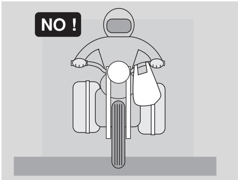
Avoid hanging bulky, heavy and/or dangerous objects on the handlebars, mudguards and forks, because the vehicle might respond more slowly in turns and its manoeuvrability could be unavoidably impaired.
Do not place bags that are too bulky on the vehicle sides and do not ride with the crash helmet hanging from its string, because it could hit people or obstacles making you lose control of the vehicle.
Do not carry any bag if it is not tightly secured to the vehicle.
Do not carry bags which protrude too much from the luggage rack or which cover the lights, horn or indicators.
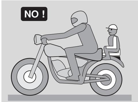
Do not carry animals or children on the glove compartment or on the luggage rack.
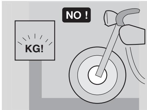
Do not exceed the maximum load allowed for each side-bag.
When the vehicle is overloaded, its stability and its manoeuvrability can be compromised.
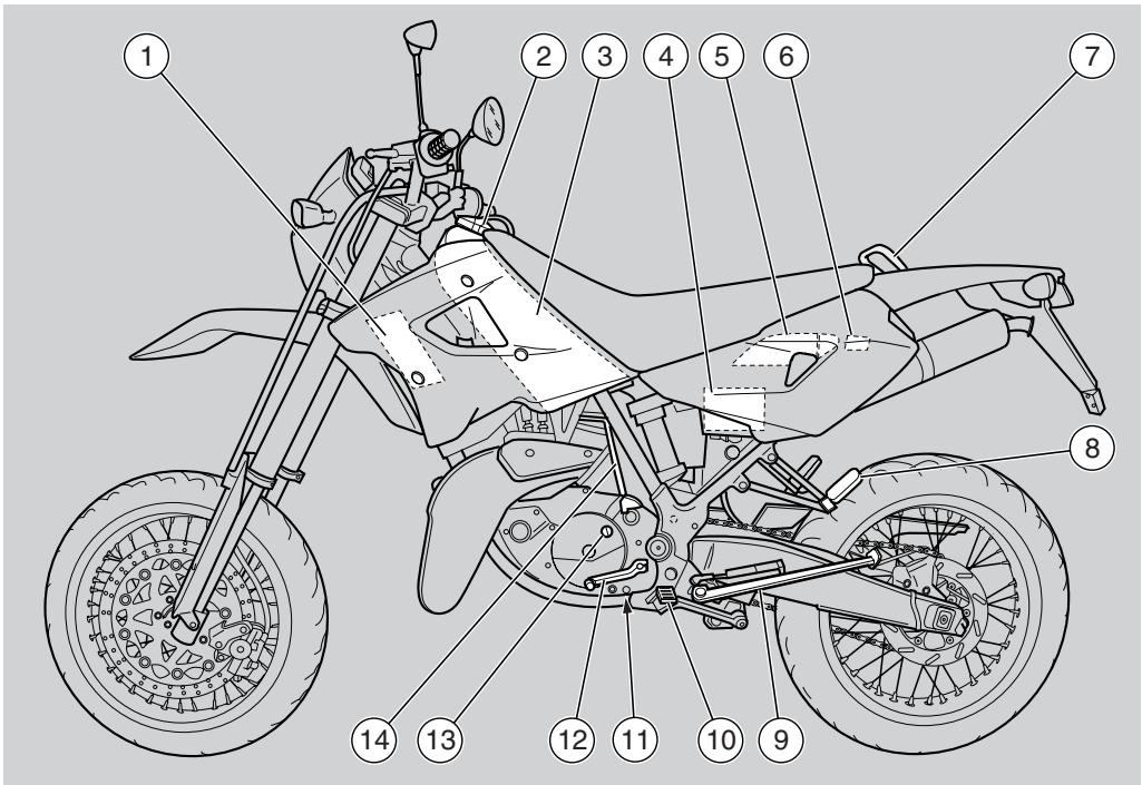
KEY
1) Coolant left radiator
2) Fuel tank plug
3) Fuel tank
4) Battery
5) Glove/tool kit compartment
6) Fuse carrier
7) Passenger grab rail
8) Passenger left footrest (snapping, closed/open)
9) Side stand
10) Rider left footrest (with spring, always open)
11) Transmission oil drain plug
12) Shifting lever
13) Transmission oil filling cap
14) Starting lever
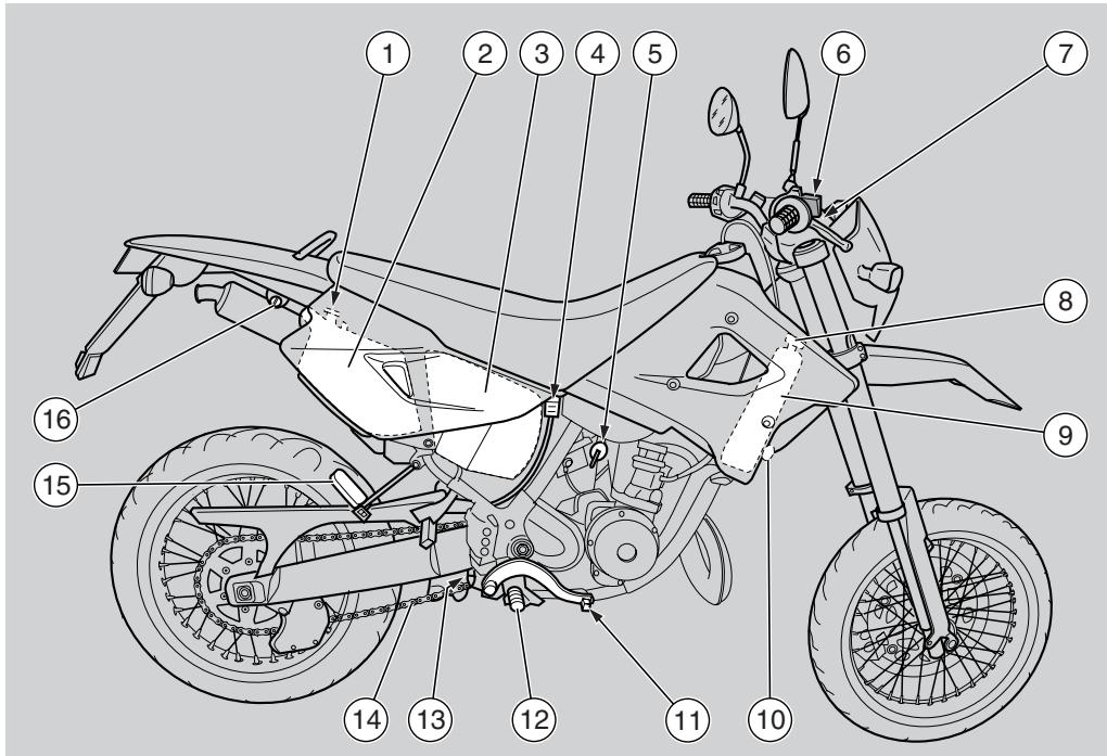
KEY
1) 2 stroke oil tank plug
2) 2 stroke oil tank
3) Air cleaner
4) Rear brake fluid tank
5) Fuel cock
6) Brake fluid reservoir (front brake)
7) Ignition switch/steering lock
8) Coolant radiator cap
9) Coolant right radiator
10) Horn
11) Rear brake control lever
12) Rider right footrest (with spring, always open)
13) Rear brake pump
14) Drive chain
15) Passenger right footrest (snapping, closed/open)
16) Crash helmet hook

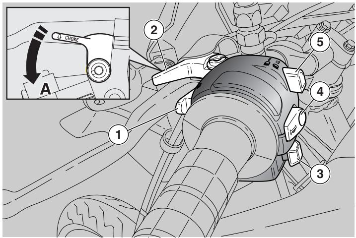
KEY
1) Direction indicator switch (↔ ⇒)
2) Horn push button (h-)
3) Dimmer switch (D - D)
4) High beam signalling push button (D)
5) Left rear-view mirror
6) Clutch lever
7) Cold start lever (▶)
8) Instruments and indicators
9) Ignition switch/steering lock (O - - - - )
10) Front brake lever
11) Right rear-view mirror
12) Throttle grip
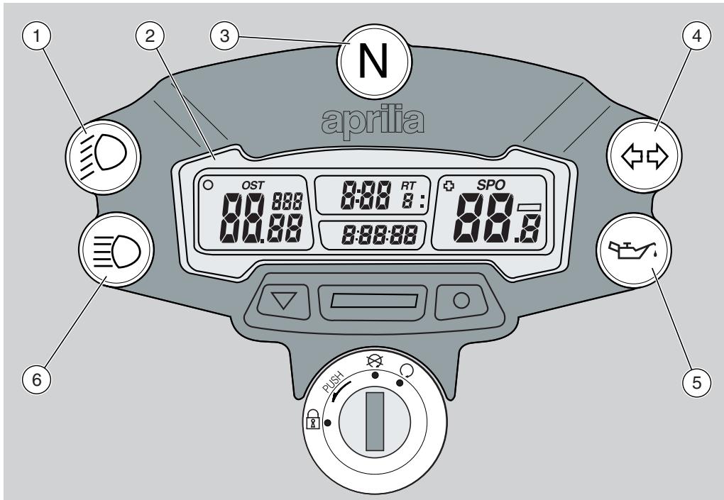
KEY
1) Green (D) low beam warning light
2) Multifunction digital display
3) Green neutral indicator warning light (N)
4) Green direction indicator warning light ( )
5) Red 2 stroke oil reserve warning light (
6) Blue high beam warning light (D)
INSTRUMENTS AND INDICATORS TABLE
| Description | Function |
| 2 stroke oil reserve warning light (◇) | Comes on, for about 0.5 seconds, whenever the ignition switch is brought to position “○”, thus testing the correct operation of the bulb. If the light does not come on in this phase, contact an Concessionario Ufficiale aprilia. ▲ CAUTION If the warning light comes on during the normal operation of the engine, this means that the 2 stroke oil reserve is being used; in this case, provide for topping up, see pag. 37 (2 STROKE OIL TANK). |
| Neutral indicator warning light (N) | It comes on when the gear is in neutral. |
| Direction indicator warning light (◇◇) | Blinks when the direction indicators are on. |
| High beam warning light (◎D) | Comes on when the headlight is in "high beam" position or when the high beam signalling is operated. |
| Low beam warning light (◎D) | It comes on when the front low beam bulbs are on. |
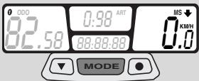
MULTIFUNCTION COMPUTER
CAUTION
The display is provided with an automatic shutoff function. In case the vehicle or the display are left unused for more than 30 minutes, the display will be automatically disabled. All the pre-set data will nevertheless be stored. The display will be automatically re-enabled as soon as one of the push Buttons is pressed or the vehicle is used again.
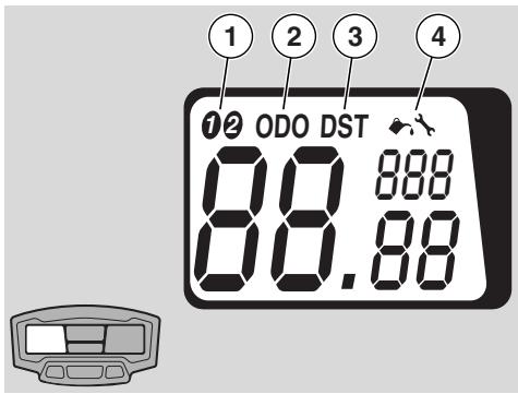
KEY
| 1-2 | Vehicle selection |
| KM/H - MPH | Mi or km selection |
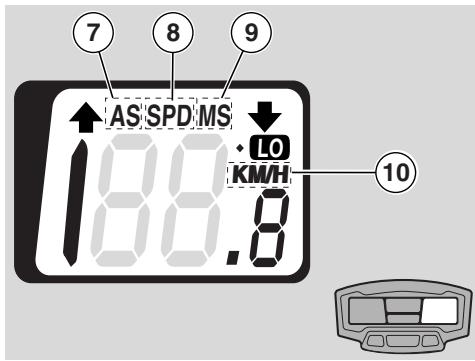
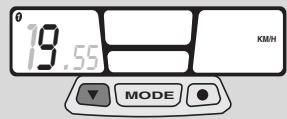
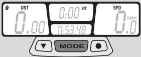
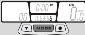
| SPD | Current speed |
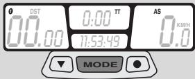
| AS | Average speed |
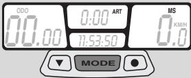
| MS | Max. speed |
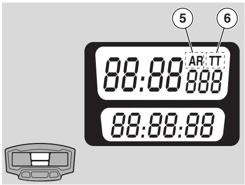
| TT | Trip meter |
| RT | Partial race time |
| ART | Total race time |
| 00:00:00 | Time 12h or 24h |
| DST | Partial distance covere vehicle |
| ODO | Total distance covere vehicle |
| ← | Lubrication warning lig |
| → | Maintenance warning |
| □ | Display backlighting |
| 10 | Low battery |
CAUTION
By simply setting the front wheel circumference, two different types of vehicles, bike 1 and bike 2, can be stored inside the multifunction computer memory.
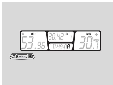
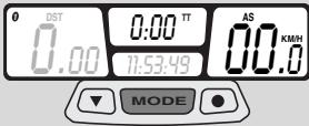
Left display: Vehicle (1), total distance covered (2), partial distance covered (3) and maintenance functions (4) can be selected;
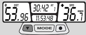
Centre display: total and partial race time (5) and trip meter (6) can be selected;
Right display: average (7), max (8) and current (9) speeds and Km/mi (10) functions can be selected.
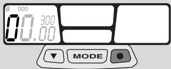
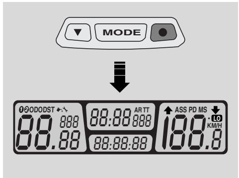
START-UP SETTING
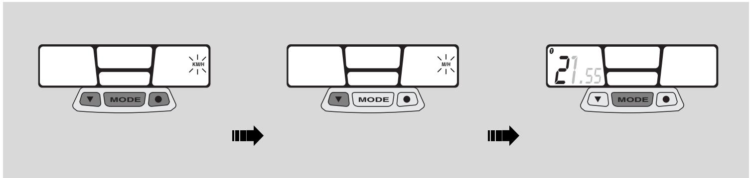
Metric system setting (KM/H or MPH)
Keep the three push buttons simultaneously pressed for about 2 seconds, then press any of them to start settings.
Press left push button to change the unit of measurement from "km" to "mi" (KM/H to MPH) or vice-versa.
Keep centre "MODE" push button pressed for about 1.5 seconds to confirm. Then start wheel diameter "WS" setting.
CAUTION
As soon as the MODE push button is pressed, the actual wheel diameter value and the first flashing datum will appear on the left display.

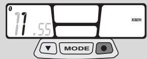


Setting the "WS" wheel diameter
To change the flashing value, press the left push button.
Press right push button to go to next value and then press left push button again to change this value.
Pre-set value 1850.
Keep centre "MODE" push button pressed for about 1.5 seconds to confirm. Then start time setting.
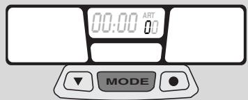
CAUTION
As soon as the MODE push button is pressed, time actual setting (24h or 12 h) will appear on the centre display.
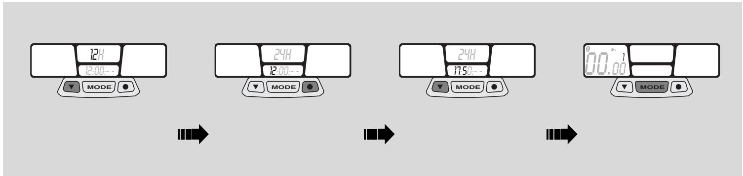
Time setting
Press left push button to select time displaying (24h or 12 h).
Press right push button to set the "hour". Press left push button to change the value.
Press right push button to set the "minutes". Press left push button again to change the value.
Keep centre "MODE" push button pressed for about 1.5 seconds to confirm. Then start preventative lubrication check.
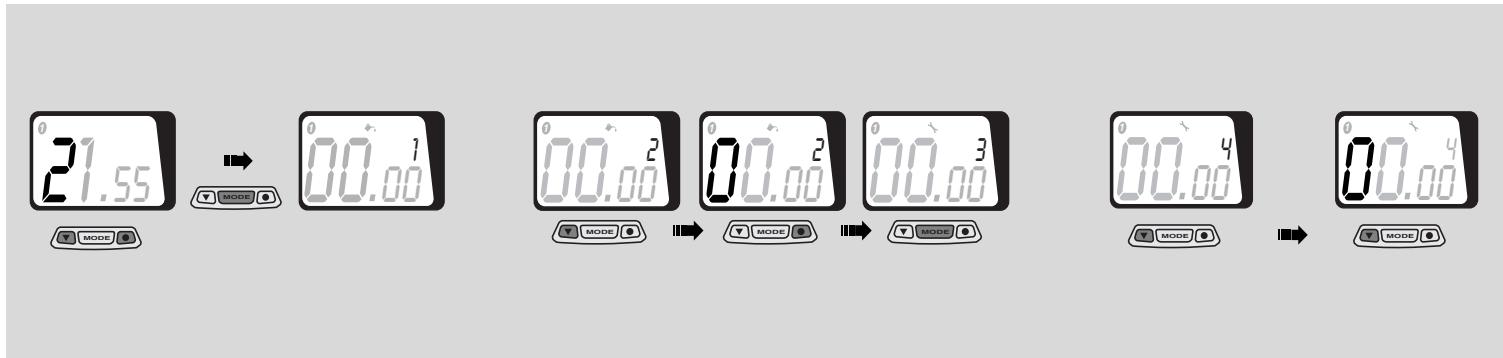
CAUTION
As soon as the MODE push button is pressed, the lubrication symbo - with the number of preventative services to be made - will appear and start flashing on the left display.
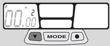
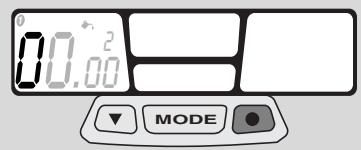


Preventative lubrication check
CAUTION
The preventative lubrication check is already pre-set after the first 100 km (60 mi) for vehicle 1 and after the first 300 km (200 mi) for vehicle 2. To change lubrication interval, refer to page pag. 25 (STANDARD SETTING).
Press left push button to modify the value.
Press right push button to shift to next value.
Keep centre "MODE" push button pressed for about 1.5 seconds to confirm. Then start preventative maintenance check.
CAUTION
If the lubrication check function is not used, set all values to zero.
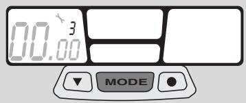
CAUTION
As soon as the MODE push button is pressed, the maintenance symbol - with the number of preventative services to be made - will appear and start flashing on the left display.
CAUTION
Checks to be managed by the user. Do not confuse with scheduled maintenance services.
Preventative maintenance check
CAUTION
The preventative maintenance check is already pre-set after the first 300km (200 mi) for vehicle 1 and after the first 990km (600 mi) for vehicle 2.
To change maintenance check interval, refer to page pag.25 (STANDARD SETTING).
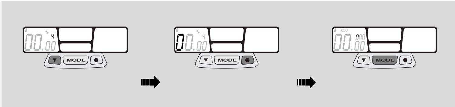
Press left push button to modify the value.
Press right push button to shift to next value.
Keep centre "MODE" push button pressed for about 1.5 seconds to confirm. Then start total distance setting (ODO).
CAUTION
As soon as the MODE push button is pressed, the ODO wording will appear on the left display.
CAUTION
Checks to be made by the user. Do not confuse with scheduled maintenance services.
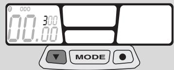


Checking the total distance covered (ODO)
Press left push button to modify the value.
Press right push button to shift to next value.
- Keep centre "MODE" push button pressed for about 1.5 seconds to confirm. Then start total race time setting (ART).
CAUTION
As soon as the MODE push button is pressed, the ART wording will appear on the centre display.
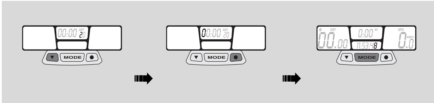
Checking the total race time (ART)
Press left push button to modify the value.
Press right push button to shift to next value.
- Keep centre "MODE" push button pressed for about 2 seconds to confirm. Start-up setting is now completed.

Programming the second vehicle
Keep the right push button pressed for about 5 seconds. The "WS" wheel diameter value of the second vehicle will appear on the left display. The menu relating to the second vehicle will be automatically enabled after a few seconds.
CAUTION
Keep the two outer push buttons pressed for about 2 seconds to enable the STANDARD SETTING programme relating to the second vehicle (bike 2).
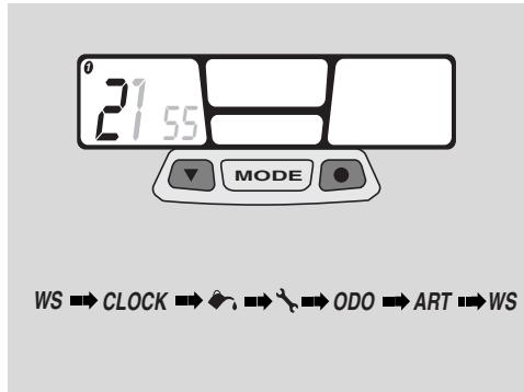
STANDARD SETTING
CAUTION
Keep the two outer push buttons pressed for about 2 seconds to enable the STANDARD SETTING programme.
This menu will allow you to modify the wheel diameter, the time setting, the vehicle lubrication and maintenance interval, the total distance covered (ODO) and the total race time (ART).
The metric system setting, KM/H to MPH or vice-versa, can be modified only from the START-UP SETTING menu.
A
B
C
A


PARAMETERS SETTING/DISPLAYING
CAUTION
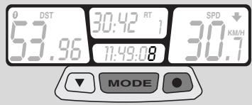
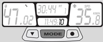
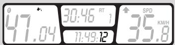
Press the centre MODE push button to scroll the different setting screens.
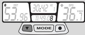
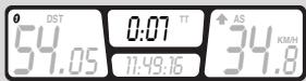
During operation, screen (A) - showing the distance covered after the last resetting (TT), the current speed, time and partial race time (RT) - will be displayed.
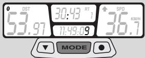
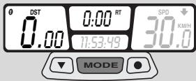
Press centre push button "MODE" to shift to screen (B) and press it again to shift again to screen (C).

CAUTION
Screens (B and C) will be displayed for 5 seconds only, then screen (A) will appear again.
A
D
E


Keep centre push button "MODE" and right push button simultaneously pressed for about 2 seconds to shift to screen (D) - showing the preventative maintenance check function - and press them again to shift again to screen (E) showing the preventative lubrication check function.
CAUTION
Screens (D and E) will be displayed for 5 seconds only. If no other button is pressed, screen (A) will be displayed again.
DISABLING THE SCHEDULED MAINTENANCE SERVICES
Whenever the scheduled maintenance or lubrication service intervals are not respected, the relating value will start flashing on the left display.
To switch this value off, keep the right and left push button simultaneously pressed for about 2 seconds.
- Keep centre push button "MODE" pressed for about 1.5 seconds to go to the wheel diameter screen.
-
Keep centre push button "MODE" pressed again for about 1.5 seconds to go to the time setting screen and to start setting the preventative lubrication check.
Press left push button to modify the value.
Press right push button to confirm this value and to shift to next value. -
Keep centre “MODE” push button pressed for about 1.5 seconds to confirm preventative lubrication values and to shift to next operation. Press left push button to modify the value.
Press right push button to confirm this value and to shift to next value.
Keep right push button pressed again until, after about 2 seconds, the starting screen (A) will appear again.
A
A
B
B


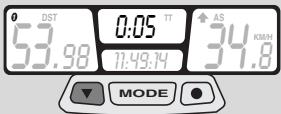
CHRONOMETER
The multifunction computer is equipped with a chronometer, to be displayed on screen (B) together with trip meter (TT).
Press left push button to enable chronometer.
Press centre push button "MODE" to display screen (B).
- Press left push button again to terminate the chronometer function.
A
B
C


RESETTING THE PARTIAL VALUES
This function is used to reset the partial values stored inside the computer memory. In particular:
- Partial distance covered (DST)
- Trip meter (TT)
-
Partial race time (RT)
Maximum speed (MS)
Average speed (AS) -
Keep the left and the centre "MODE" push buttons simultaneously pressed for about 2 seconds.
Screen (A) with the reset values will be displayed.
Press centre push button "MODE" to shift to screen (B) and reset the values.
Press centre push button "MODE" again to shift to screen (C) and reset the values.
CAUTION
Screens (B and C) will be displayed for 5 seconds only, then screen (A) will appear again.
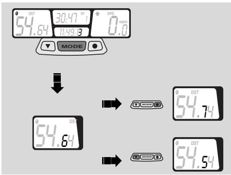
ALIGNING THE PARTIAL VALUES (TRIP)
The partial distance covered (DST) can be modified by increasing or decreasing the value appearing on the display. This function can be used during competitions to make the displayed value match the one relating to the racetrack.
CAUTION
Do not use this function to reset the value (DST); to reset partial values refer to page pag. 30 (RESETTING THE PARTIAL VALUES).
Keep the centre "MODE" push button pressed for about 3 seconds.
Press the right push button to increase the value.
Press the left push button to decrease the value.
Screen (A), with the changes made, will be displayed after about 3 seconds.
BACKLIGHTING
Press right push button to enable display backlighting, The light will be automatically switched off after 4 seconds.
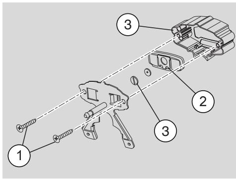
CHANGING THE BATTERY
Remove headlight fairing.
Loosen the 2 cross-head screws between instrument holder and metal plate.
Disconnect the 2-way connector from speedometer transmission unit.
To remove the digital instrument from its holder, slightly press on LCD side.
Disconnect the "sliding shoe" from the digital instrument body.
Loosen the battery cover cap behind the digital instrument.
Change the "CR2032" battery.
CONTROLS ON THE LEFT SIDE OF THE HANDLEBAR
CAUTION
The electrical parts work only when the ignition switch is in position “○”.
1) HIGH BEAM SIGNALING PUSH BUTTON (E0)
It makes it possible to use the high beam for signalling to forthcoming vehicles while overtaking and in case of peril and/or emergency.
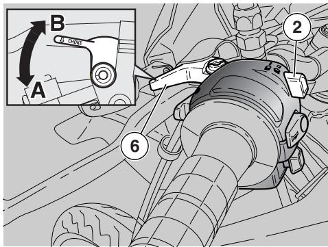
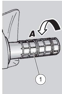
2) COLD START LEVER (▶)
The starter for the cold start of the engine is operated by rotating the lever "| × |" anticlockwise (Pos. A).
To disconnect the starter, return the lever "▶" to its initial position.
3) DIRECTION INDICATOR SWITCH (◇◇)
To indicate the turn to the left, move the switch to the left; to indicate the turn to the right, move the switch to the right.
To turn off the direction indicator, press the switch.
4) HORN PUSH BUTTON (▶)
The horn is activated when the push button is pressed.
5) DIP SWITCH (D - D)
When the dip switch is in the “ D ”, position, the high beams will come on; while when the dip switch is in the “ D ”, position, the low beams will come on.
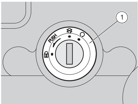
IGNITION SWITCH
The ignition switch (1) is positioned on the upper plate of the steering column.
CAUTION
The key operates the ignition switch/steering lock. Two keys are supplied together with the vehicle (one spare key).
STEERING LOCK
WARNING
Never turn the key to position "B" in running conditions, in order to avoid losing control of the vehicle.
OPERATION
To lock the steering:
Turn the handlebar completely leftwards.
Turn the key to position "X".
CAUTION
Turn the key and steer the handlebar at the same time.
Press and rotate the key anticlockwise (leftwards), steer the handlebar slowly until the key reaches position "
Extract the key.
| Position | Function | Key removal |
| Steering lock | The steering is locked. It is neither possible to start the engine, nor to switch on the lights. | It is possible to remove the key. |
| ×× | Neither the engine, nor the lights can be switched on. | It is possible to remove the key. |
| ○ | The engine and the lights can be switched on. | It is not possible to remove the key. |
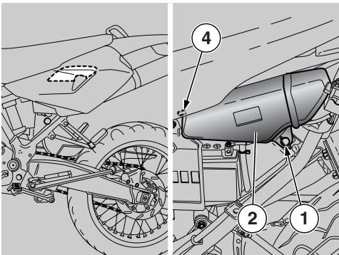
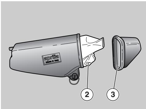
GLOVE/TOOL KIT COMPARTMENT
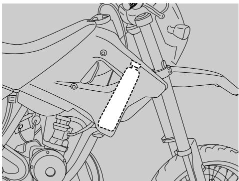
The glove/tool kit compartment is positioned under the left side cover; to reach it:
Remove the left side cover, see pag. 58 (REMOVING THE SIDE COVERS)
Turn the quick fastening screw (1) by 1/4 of a turn.
Take compartment (2) out of its location.
Remove the compartment lock (3) from behind.
NOTE At reassembly, be careful to properly fit centering pin (4).
The tool kit (2) includes:
- n^1 tool case
- n^ 14 ~mm bent Allen spanner
- n° 15 mm bent Allen spanner
- n° 16 mm bent Allen spanner
- n^18 mm bent Allen spanner
- n^17x8mm double fork spanner
- n^1 10x13 mm double fork spanner
- n^1 19 mm fork spanner
- n^1 21x24 mm double socket spanner
- n° 1 cross-/cut-headed screwdriver
- n^1 screwdriver handle
- n° 1 3x70 mm cross-headed screwdriver
Max. allowed weight: 1.5kg
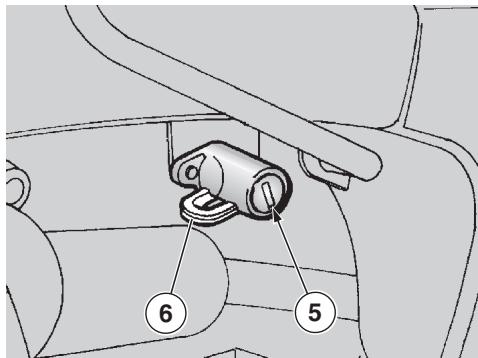
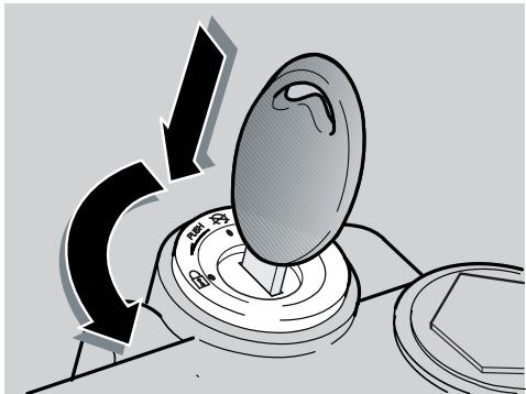
CRASH HELMET HOOK
Thanks to the crash helmet hook, you no longer have to carry the crash helmet with you every time you park the vehicle.
WARNING
Do not ride with the crash helmet hanging from the hook, as this may seriously compromise your safety.
To hang the crash helmet, proceed as follows:
Insert the key in the lock (5).
Rotate the key clockwise.
Pass the crash helmet cable through the hook (6).
Rotate the key anticlockwise.
CAUTION
Make sure that you have correctly closed the hook (6).
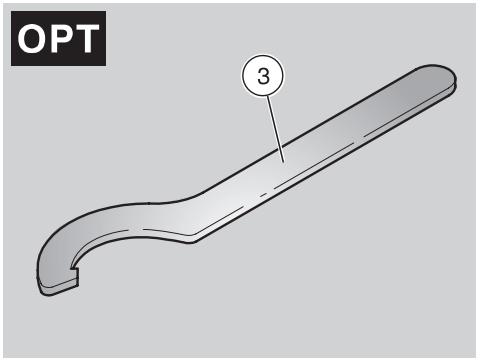
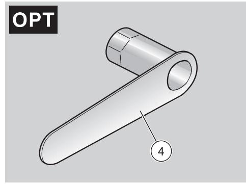
SPECIAL TOOLS OPT
To perform some specific operations, it is advisable to use the following special tools (to be requested to an aprilia Official Dealer).
| Tool | Operations | Page |
| Square pin spanner (3) | Rear shock ab-sorber ring adjust-ment. | 42 |
| Special soc-ket spanner (4) | Clutch clearance adjustment. | 69 |
FUEL
WARNING
The fuel used for internal combustion engines is extremely inflammable and in particular conditions it can become explosive. It is important to carry out the refuelling and the maintenance operations in a well-ventilated area, with the engine off. Do not smoke while refuelling or near fuel vapours, in any case avoid any contact with naked flames, sparks and any other heat source to prevent the fuel from catching fire or from exploding. Further, prevent fuel from flowing out of the fuel filler, as it could catch fire when getting in contact with the red-hot surfaces of the engine.
In case some fuel has accidentally been spilt, make sure that the area has completely dried before starting the vehicle.
Since petrol expands under the heat of the sun and due to the effects of sun radiation, never fill the tank to the brim. Screw the plug up carefully after refuelling. Avoid any contact of the fuel with the skin and the inhalation of vapours; do not swallow fuel or pour it from a receptacle into another by means of a tube.
DO NOT DISPOSE OF FUEL IN THE ENVIRONMENT
KEEP AWAY FROM CHILDREN
Use only unleaded petrol, in conformity with the DIN 51607 standard, min. O.N. 95 (N.O.R.M.) and 85 (N.O.M.M.).
FUEL TANK CAPACITY (reserve included): 11 l
TANK RESERVE: 1.3 (mechanical reserve)
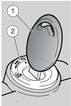
To refuel, proceed as follows:
Unscrew and remove the fuel tank plug (1).
Refuel.
TRANSMISSION OIL
Check the transmission oil level every 4000 km, see pag. 60 (CHECKING THE TRANSMISSION OIL LEVEL AND TOPPING UP).
Change gearbox oil at the end of the running-in period, and then every 12,000 km, see pag.61 (CHANGING THE TRANSMISSION OIL).
CAUTION
Use high-quality 75W-90 oil, see pag. 88 (LUBRICANT CHART).
WARNING
Engine oil can cause serious damage to the skin if handled every day and for long periods.
Wash your hands carefully after using the oil.
Do not dispose of the oil in the environment.
Put it in a sealed container and take it to the filling station where you usually buy it or to an oil salvage center.
In case any maintenance operation has to be carried out, it is advisable to use latex gloves.
2 STROKE OIL TANK
Top up the 2 stroke oil tank every 500~km . The vehicle is provided with a separate mixer that ensures the mixing of petrol and oil for the engine lubrication, see pag. 88 (LUBRICANT CHART).
The 2 stroke oil reserve is indicated by the coming on of the 2 stroke oil reserve warning light "..." positioned on the dashboard, see pag. 15 (INSTRUMENTS AND INDICATORS).
WARNING
The use of the vehicle without 2 stroke oil seriously damages the engine.
If you run out of oil in the 2 stroke oil tank or if the 2 stroke oil pipe has been removed, contact an aprilia Official Dealer, who will provide for bleeding the system.
This operation is indispensable, since the running of the engine with air in the 2 stroke oil system may result in serious damage to the engine.
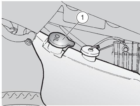
To introduce the 2 stroke oil in the tank, proceed as follows:
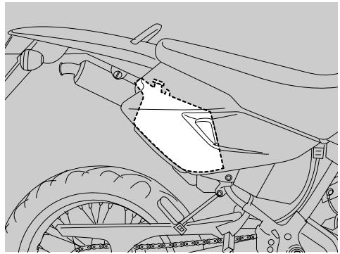
Remove the right side cover, see pag. 58 (REMOVING THE SIDE COVERS).
Remove the plug (1).
TANK CAPACITY (reserve included): 1.25 l
TANK RESERVE: 0.5l
WARNING
Carefully wash your hands after handling the oil.
Do not dispose of the 2 stroke oil in the environment.
KEEP AWAY FROM CHILDREN

BRAKE FLUID - recommendations
CAUTION
This vehicle is provided with front and rear disc brakes, with separate hydraulic circuits.
The following information refers to a single braking system, but is valid for both.
WARNING
Sudden resistance or clearance problems on the brake lever may be due to troubles in the hydraulic system.
For any doubt regarding the perfect functioning of the braking system and in case you are not able to carry out the usual checking operations, contact your aprilia Official Dealer .
WARNING
Make sure that the brake discs are
neither oily nor greasy, especially after maintenance or checking operations.
Check that the brake cables are neither twisted nor worn out.
Prevent water or dust from accidentally getting into the circuit.
In case maintenance operations are to be performed on the hydraulic circuit, it is advisable to use latex gloves.
If the brake fluid gets in contact with the skin or the eyes, it can cause serious irritations.
Carefully wash the parts of your body that get in contact with the liquid.
Consult a doctor or an oculist if the liquid gets in contact with your eyes.
Do not dispose of the brake fluid in the environment.
KEEP AWAY FROM CHILDREN
WARNING
When using the brake fluid, take care not to spill it on the plastic or painted parts, since it damages them irreparably.
DISC BRAKES
WARNING
The brakes are the parts that most ensure your safety and for this reason they must always be perfectly working; check them before every trip.
The brake fluid must be changed once a year by an aprilia Official Dealer .
Use brake fluid of the type specified in the lubricant chart, see pag. 88 (LUBRICANT CHART).
When the disc pads wear out, the level of the fluid inside the reservoir decreases to automatically compensate for their wear.
The front brake reservoir is positioned near the front brake lever coupling.
The rear brake reservoir is positioned on the right side of the vehicle, before the air filter casing.
Periodically check the brake fluid level in the tanks, see pag. 39 (FRONT BRAKE), pag. 40 (REAR BRAKE) and the wear of the pads, see pag. 70 (CHECKING THE BRAKE PAD WEAR).
FRONT BRAKE
Carefully read pag. 38 (BRAKE FLUID - recommendations) and (DISC BRAKES).
CHECKING
CAUTION
Position the vehicle on firm and flat ground.
To check the brake fluid level, proceed as follows:
Position the vehicle on the stand.
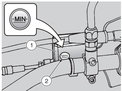
- Rotate the handlebar leftwards, so that the fluid contained in the reservoir (1) is parallel to the "MIN" mark stamped on the glass (2).
Make sure that the level of the brake fluid contained in the tank exceeds the "MIN" mark stamped on the glass (2).
If not, provide for topping up.
TOPPING UP
WARNING
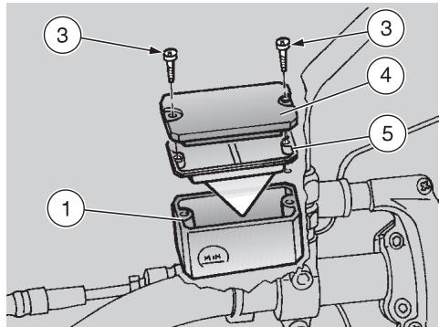
The brake fluid may flow out of the reservoir. Do not operate the brake lever if the screws (3) are loose or, most important, if the brake fluid tank cover has been removed.
Unscrew the two screws (3).
Remove the cover (4).
WARNING
In order not to spill the brake fluid while topping up, keep the fluid in the reservoir parallel to the reservoir rim.
Remove the gasket (5).
Fill the tank with brake fluid, see pag. 88 (LUBRICANT CHART), until it covers the glass completely.
Put back the gasket (5) in its seat correctly.

Put back the cover (4).
Screw and tighten the two screws (3).
WARNING

Check the braking efficiency. If necessary, contact your aprilia Official Dealer.
In case of excessive movement of the brake lever, of excessive elasticity or in case there is air in the circuit, contact your aprilia Official Dealer, since it may be necessary to bleed the system.
REAR BRAKE
Carefully read pag. 38 (BRAKE FLUID - recommendations) and (DISC BRAKES).
CHECKING
CAUTION
Position the vehicle on firm and flat ground.
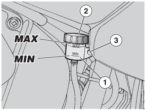
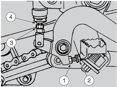
- Keep the vehicle in vertical position, so that the fluid contained in the tank (1) is parallel to the plug (2).
- Make sure that the fluid level exceeds the "MIN" mark.
If the fluid does not reach the "MIN" mark, provide for topping up.
TOPPING UP
WARNING
The brake fluid may flow out of the tank. Do not operate the rear brake lever if the brake fluid tank plug is loose or has been removed.
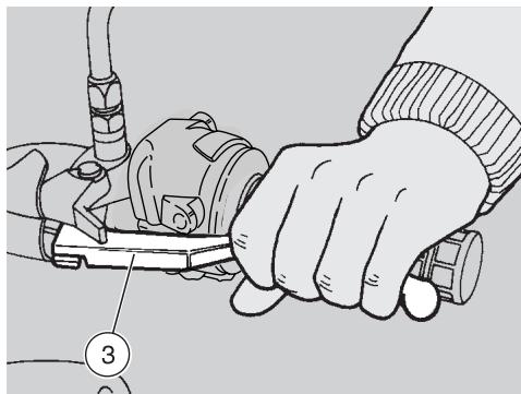
Loosen retaining screw (3), and remove brake reservoir, but leave it connected to the rear brake system line.
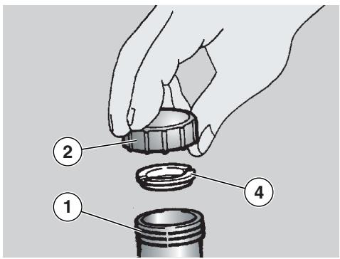
Unscrew and remove the plug (2).
CAUTION
In order not to spill the brake fluid while topping up, keep the fluid in the tank parallel to the tank rim (in horizontal position).

Remove the gasket (4).
- By means of a syringe, top up the brake fluid reservoir (1), see pag. 88 (LUBRICANT CHART) until reaching the "MAX" mark.
Take care to correctly position gasket (4), and refit plug (2).
Secure rear brake system reservoir in place with retaining screw (3). Do not forget to fit also the relevant washer.
WARNING
Check the braking efficiency. If necessary, contact your aprilia Official Dealer .
In case of excessive stroke of the brake lever, of excessive elasticity or in case there is air in the circuit, contact your aprilia Official Dealer, since it may be necessary to bleed the system.
ADJUSTING
The brake lever is installed in ergonomic position on assembly of the vehicle. If necessary, it is possible to adjust the brake lever height, by proceeding as follows:
Loosen the lock nut (1).
Unscrew the brake adjuster (2) completely.
Screw the lock nut (3) completely on the pump control rod (4).
Screw the pump control rod (4) completely, then unscrew it by giving 3-4 turns.
- Unscrew the brake adjuster (2) and move the brake lever (5) to the desired height.
Lock the brake adjuster (2) by means of the lock nut (1).
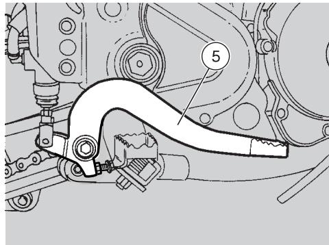
Unscrew the pump control rod (4) and bring it in contact with the pump piston.
Screw the rod in order to ensure a minimum clearance of 0.5 ÷ 1 ~mm between the pump control rod (4) and the pump piston.
WARNING
Ensure that there is some play between the master cylinder actuating rod (4) and piston, or the brake will drag, leading to early wear of friction elements.
Play between master cylinder actuating rod and piston: 0.5 ÷ 1 mm.
Lock the pump control rod by means of the lock nut (3).
WARNING
Check the braking efficiency.
If necessary, contact an aprilia Official Dealer.
After the adjustment, make sure that the wheel rotates freely with released brake.
ADJUSTING THE CLUTCH
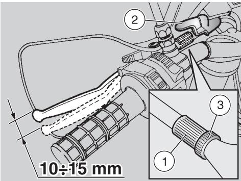
Adjust the clutch and if the engine stops or tends to advance when the clutch lever is pulled and the gears are engaged, or if the clutch slips causing a delay in the acceleration in comparison with the engine speed. Minor adjustments can be carried out by means of the adjuster (1):
Withdraw the protection element (2).
Loosen the nut (3) (by screwing it).
- Rotate the adjuster (1), until the idle stroke at the end of the clutch lever is about 10 ÷ 15 ~mm (see figure).
Tighten the nut (3) (by unscrewing it) and lock the adjuster (1).
- Check the idle stroke at the end of the clutch lever.
Put back the protection element (2).
If the adjuster (1) is completely screwed or unscrewed, or if it is not possible to obtain the correct idle stroke:
- Withdraw the protection element (2).
Tighten the nut (3) completely on the adjuster (1).
Tighten the adjuster (1) completely.
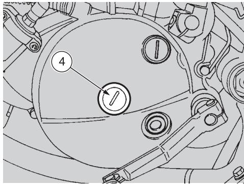
Unscrew and remove the plug (4) by means of a cut-headed screwdriver (or a coin).
CAUTION
The special spanner (5) is available at any aprilia Official Dealer.
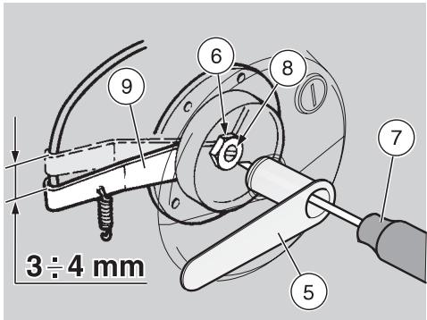
Insert the special spanner (5) and loosen the inner nut (6).
Insert a cut-headed screwdriver (7) in the special spanner (5) and tighten the adjusting screw (8) completely.
Loosen the adjusting screw (8) by giving it half a turn, which corresponds to 3 ÷ 4 mm of the lever (9) stroke.
Keep the adjusting screw (8) locked by means of the screwdriver (7), act on the special spanner (5) and tighten the inner nut (6).
Tighten the plug (4) again.
Check the idle stroke at the end of the clutch lever (10÷15 mm).
Start the engine.
Operate the clutch completely and and engage the 1st gear. Make sure that the engine does not stop, that the vehicle does not tend to advance or that the clutch does not slip during the acceleration phase or while the vehicle is running.
WARNING
If it is not possible to obtain a correct adjustment or if the clutch does not function properly, contact your aprilia Official Dealer.
CAUTION
Make sure that the clutch cable is intact: it must not present flattened parts and the sheath must not be worn out in any point.
Periodically lubricate the clutch cable with a suitable lubricant, see pag. 88 (LUBRICANT CHART), in order to avoid its untimely wear and corrosion.
TYRES
This vehicle is provided with tyres with inner tube.
WARNING
Periodically check the tyre inflation pressure at room temperature, see pag. 85 (TECHNICAL DATA).
If the tyres are hot, the measurement is not correct.
Carry out the measurement especially before and after long rides.
If the inflation pressure is too high, the ground unevenness cannot be dampened and is therefore transmitted to the handlebar, thus compromising the driving comfort and reducing the road holding during turns.
If, on the contrary, the inflation pressure is too low, the tyre sides are under greater stress and the tyre itself may slip on the rim or it may become loose, with consequent loss of control of the vehicle.
In case of sudden braking the tyres could even get out of the rims.
Further, the vehicle could skid while turning.
Check the surface and the wear of the tyres, since tyres in bad conditions can impair both the grip and the controllability of the vehicle.
Change the tyre when it is worn out or in case of puncture on the tread side, if the puncture is larger than 5mm
After repairing a tyre, have the wheels balanced. Use only tyres in the size suggested by aprilia, see pag. 85 (TECHNICAL DATA).
Make sure that the tyres always have their valve sealing caps on, to prevent them from suddenly going flat.
Change, repair, maintenance and balancing operations are very important and should be carried out by qualified technicians with appropriate tools.
For this reason, it is advisable to have the above mentioned operations carried out by an aprilia Official Dealer or by a qualified tyre repairer.
If the tyres are new, they may still be covered with a slippery film: drive carefully for the first miles.
Do not oil the tyres with unsuitable fluids.
If the tyres are old, even if not completely worn out, they may become hard and may not ensure good road holding.
In this case, replace them.
COOLANT
WARNING
Do not use the vehicle if the coolant is below the minimum prescribed level.
NOTE Perform the maintenance operations with half the frequency indicated if the vehicle is used in rainy or dusty areas, on uneven surfaces or on racetracks.
Before departure, check the coolant level, see pag. 45 (CHECKING AND TOPPING UP); have the coolant changed every two years: for this operation, contact an aprilia Official Dealer.
WARNING
The coolant is noxious: do not swallow it; if the coolant gets in contact with the skin or the eyes, it can cause serious irritations.
If the coolant gets in contact with your skin or eyes, rinse with plenty of water and consult a doctor. If it is swallowed, induce vomit, rinse mouth and throat with plenty of water and consult a doctor without delay.
KEEP AWAY FROM CHILDREN.
WARNING
Be careful not to spill the coolant on the red-hot parts of the engine: it may catch fire and send out invisible flames.
In case maintenance operations are to be performed, it is advisable to use latex gloves.
Have the coolant changed by an aprilia Official Dealer.
The coolant is made up of 50% water and 50% antifreeze.
This mixture is ideal for most running temperatures and ensures good protection against corrosion.
Li is advisable to keep the same mixture also in the hot season, since in this way losses due to evaporation are reduced and it is not necessary to top up very frequently.
The mineral salt deposits left in the radiator by evaporated water are thus reduced and the efficiency of the cooling system remains unchanged.
If the outdoor temperature is below 0^ , check the cooling circuit frequently and if necessary increase the antifreeze concentration (up to maximum 60% ).
For the cooling solution use distilled water, in order not to damage the engine.
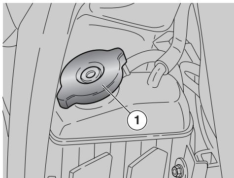
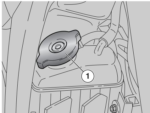
WARNING
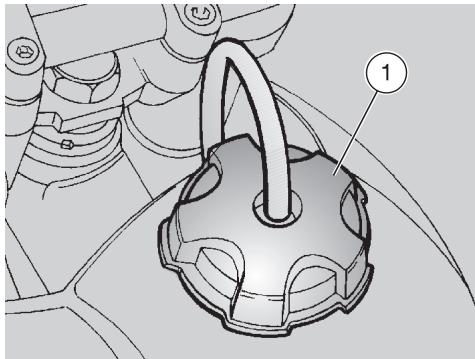
Do not remove the radiator cap (1) when the engine is hot, since the coolant is under pressure and its temperature is high.
CHECKING AND TOPPING UP
WARNING
Check the coolant level and top up the expansion tank with cold engine.
- Stop the engine and wait until it has cooled down.
CAUTION
Position the vehicle on firm and flat ground.
- Keep the vehicle in vertical position, with the two wheels resting on the ground.
Rotate the radiator cap (1) anticlockwise, giving it one click.
Wait for a few seconds, in order to permit the bleeding of any pressure present in the system.
Rotate the radiator cap (1) anticlockwise again and remove it.
- Check if the coolant covers the radiator plates completely.
If necessary, top up with coolant, see pag. 88 (LUBRICANT CHART), until covering the radiator plates completely.
WARNING
Do not exceed this level, otherwise the fluid will flow out of the tank when the engine is running.
WARNING
The coolant is noxious: do not swallow it; if the coolant gets in contact with the skin or the eyes, it can cause serious irritations.
Do not use your fingers or any other object to check if there is enough coolant.

CAUTION
Do not put additives or other substances into the fluid.
If you use a funnel or other similar items, make sure that they are perfectly clean.
Put back the radiator cap (1).
WARNING
In case of excessive consumption of coolant and in case the tank remains empty, make sure that there are no leaks in the circuit.
Have it repaired by an aprilia Official Dealer.

SILENCER
WARNING
Do not park the vehicle close to dry underbrush or within children's reach as the catalytic muffler reaches very high temperatures during use. Take thus special care and avoid any kind of contact before it has completely cooled down.
The vehicle is equipped with a silencer with ibivalent rhodium-platinum metal catalytic muffler.
This device provides for the oxidation of the CO (carbon monoxide) and of the HC (unburned hydrocarbons) contained in the exhaust gases, changing them into carbon dioxide and steam, respectively.
Due to the catalytic reaction, the high temperature reached by the exhaust gases makes for the burning of the oil particles, thus keeping the silencer clean and eliminating the exhaust fumes.
To have the catalytic converter function correctly and for long and to reduce possible problems regarding the soiling of the thermal unit and of the exhaust, it is necessary to avoid covering long distances with the engine running at constantly low rpm.
It is sufficient to alternate these periods with periods in which the engine runs at relatively high rpm, even if only for a few seconds, but rather frequently.
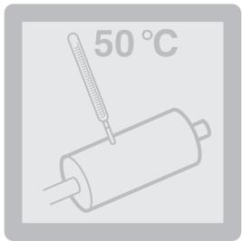
What has been stated above assumes particular importance for the cold starting of the engine: in this case, in order to reach a rpm regime sufficient to enable the "priming" of the catalytic reaction, just make sure that the temperature of the thermal unit has reached at least 50^ which generally occurs a few seconds after starting the engine.
WARNING
Do not use leaded petrol, since it causes the destruction of the catalytic converter.
INSTRUCTIONS FOR USE

WARNING
Before departure, always carry out a preliminary checking of the vehicle to make sure that it functions correctly and safely, see the following table (PRELIMINARY CHECKING OPERATIONS). The non-performance of these checking operations can cause severe personal injuries or damages to the vehicle.
Do not hesitate to consult your aprilia Official Dealer in case there is something you do not understand about the functioning of some controls or in case you suspect or discover some irregularities.
It does not take long to carry out a check-up and this operation ensures you much more safety.
PRELIMINARY CHECKING OPERATIONS
| Component | Check | Page |
| Front and rear disc brakes | Check the functioning, the idle stroke of the control levers, the fluid level and make sure there are no leaks. Check the wear of the pads. If necessary, top up the fluid tank. | 38-39-40-70 |
| Accelerator | Make sure that it works smoothly and that it is possible to open and close it completely, in all steering positions. If necessary, adjust and/or lubricate it. | 71 |
| 2 stroke oil/ transmission oil | Check and/or top up if necessary. | 36-37-60-61 |
| Wheel/tyres | Check the tyre surface, the inflation pressure, wear and tear and any damage. | 43 |
| Brake levers | Make sure that they work smoothly. If necessary, lubricate the articulations and adjust the stroke. | 39-40 |
| Clutch | The idle stroke at the end of the clutch lever must be about 10 mm; the clutch must operate without jerking and/or slipping. | 42 |
| Steering | Make sure that the steering rotates smoothly, without any clearance or slackening. | — |
| Side stand and center stand | Make sure that it works smoothly and that the spring tension brings it back to its normal position. If necessary, lubricate joints and hinges. | 77 |
| Fastening elements | Make sure that the fastening elements are not loose. If necessary, adjust or tighten them. | — |
| Drive chain | Check the slack. | 66-67 |
| Fuel tank | Check the fuel level and top up, if necessary. Make sure there are no leaks or air bubbles in the circuit. | 36-82 |
| Coolant | Check level | 44-45 |
| Lights, warning lights, horn and electric devices | Check the proper functioning of the acoustic and visual devices. Change the bulbs or intervene in case of failure. | 78÷81 |
STARTING
WARNING
Do not position any object inside the front part of the fairing (between the handlebar and the dashboard), in order not to hinder the rotation of the handlebar and visibility toward the dashboard.
NOTE Before starting the engine, carefully read chapter "safe drive", see p. 5 (SAFE DRIVE).
WARNING
Exhaust gases contain carbon monoxide, which is extremely noxious if inhaled. Avoid starting the engine in closed or badly-ventilated rooms. The non-observation of this warning may cause loss of consciousness or even lead to death by asphyxia.
Position the vehicle on the stand.
Move to the left side of the vehicle.
Or:
Let the stand up.
Get on the vehicle.
Then:
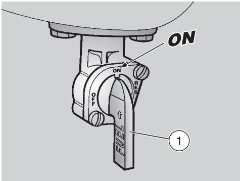
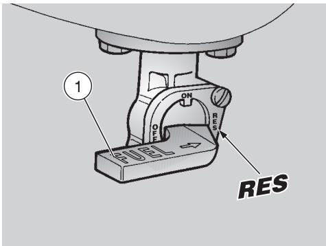
Rotate the fuel tap lever (1) to position "ON".
Make sure that the dimmer switch (2) is in position ^
Rotate the key (3) and move the ignition switch to position "O".
At this point:
- the red 2 stroke oil reserve warning light "..." comes on on the dashboard, see and 15 (INSTRUMENTS AND INDICATORS).
Lock the front wheel, by pulling the front brake lever (4).
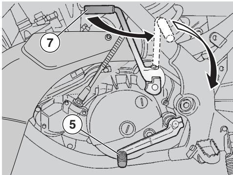
Position the shifting lever (5) in neutral (green warning light "N" on).
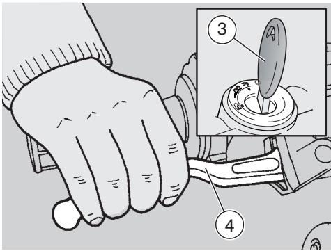
If the vehicle is started with cold engine, rotate the cold start lever " |× | (6) anticlockwise (Pos. A).
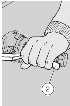
Rotate the start pedal (7) outwards.
WARNING
Do not press the start pedal when the engine is running.
Press the start pedal (7) with energy and release it immediately. If necessary, repeat this operation until the engine starts.
Keep the front brake lever (4) pulled and do not accelerate until you start.
WARNING
Never leave abruptly with cold engine. To reduce the emission of polluting substances and the consumption of fuel, warm the engine up by proceeding at low speed for the first miles.
After warming up the engine, rotate the cold start lever "1" (6) clockwise (Pos. B).
Starting with flooded engine
If the starting is not carried out properly, or if there is too much fuel in the intake ducts, the engine may get flooded.
To clean a flooded engine:
Carry out the first twelve operations described for the starting procedure.
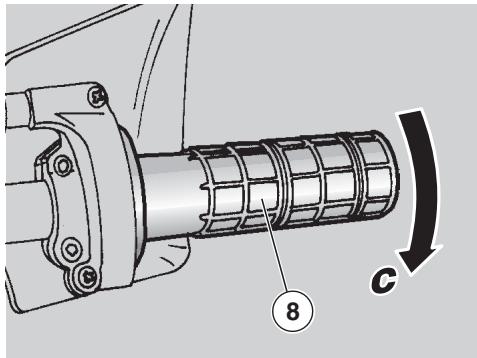
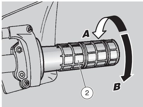
Rotate the throttle grip (8) completely (Pos. C).
WARNING
Do not press the start pedal when the engine is running.
Press the start pedal (7) with energy a few times and release it immediately.
Starting with cold engine
When the room temperature is low (near or below 0^ ), it may be difficult to start the engine at the first attempt.
In this case:
Rotate the cold start lever " | | (6) anticlockwise (Pos. A).
WARNING
Do not press the start pedal when the engine is running.
Slightly rotate the throttle grip (8) and at the same time press the start pedal (7) with energy a few times, releasing it immediately afterwards.
If the engine starts
Release the throttle grip (8).
Rotate the cold start lever " | | (6) clockwise (Pos. B).
If the idling is unstable, twist the throttle grip (8) slightly and frequently.
If the engine does not start
Wait for a few seconds and then repeat the starting procedure.
STARTING AFTER A LONG PERIOD OF INACTIVITY
After a long period of inactivity, push the start pedal (7) with energy for a few times without accelerating, in order to ensure the filling of the fuel circuit.
To start the engine, slightly open the throttle and carry out the starting procedure.
DEPARTURE AND DRIVE
WARNING
Do not position any object inside the front part of the fairing (between the handlebar and the dashboard), in order not to hinder the rotation of the handlebar and visibility toward the dashboard.
NOTE Before starting the engine, carefully read chapter "safe drive", see p. 5 (SAFE DRIVE).
If you run out of the "standard" fuel quantity while riding, move the fuel tap lever (1) to position "RES", in order to use the fuel reserve.
Fuel reserve: 1.3 (mechanical reserve).
CAUTION
Refuel as soon as possible, see pag. 36 (FUEL).
WARNING
If you drive without passenger, make sure that the passenger footrests are folded. While riding, keep your hands on the grips and your feet on the footrests.
NEVER RIDE IN ANY POSITION OTHER THAN THOSE INDICATED.
If you drive with a passenger, instruct him/her so that he/she does not create problems during manoeuvres.
To leave:
Adjust the inclination of the rear-view mirrors correctly.
WARNING
With the vehicle at rest, try to get acquainted with the use of the rear-view mirrors.
Start the engine, see pag. 48 (STARTING).
Ride at reduced speed for the first miles, in order to warm the engine up.
With released throttle grip (2) (Pos. A) and engine idling, pull the clutch lever (3) completely.
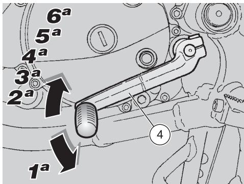
Engage the first gear, by pressing the shifting lever (4) downwards.
Release the brake lever (pulled on the starting).
WARNING
On departure, the abrupt release of the clutch lever may cause the engine to stall or the vehicle to jerk forwards.
Never accelerate abruptly or excessively when releasing the clutch lever, in order to prevent the clutch from "slipping" (slow release) or the front wheel from raising "rearing up" (quick release).
- Slowly release the clutch lever (3) and at the same time accelerate by rotating the throttle grip moderately (2) (Pos. B). The vehicle will start moving.
WARNING
Do not exceed the recommended rpm and speeds, see p. 37 (RUNNING-IN).
Increase the speed by gradually rotating the throttle grip (2) (Pos. B), without exceeding the max. speed (and the recommended rpm) in each gear, see pag. 53 (RUNNING-IN).
To engage the second gear:
WARNING
Proceed quickly. Never ride the vehicle at too low rpm.
Release the throttle grip (2) (Pos. A), pull the clutch lever (3) and lift the shifting lever (4). Release the clutch lever (3) and accelerate.
Repeat the last two operations and shift up.
The downshifting should be carried out in the following situations:
When riding downhill or when braking, in order to increase the braking action by using the compression of the engine.
- When riding uphill, if the gear engaged is not suitable to the speed (high gear, moderate speed) and the engine rpm decreases.
WARNING
Shift the gears one by one; the simultaneous downshifting of more than one gear may make you exceed the maximum rpm (red line). Before and during the downshifting, release the throttle grip and decelerate, in order to avoid the "red line".
To shift down, proceed as follows:
Release the throttle grip (2) (Pos. A).
If necessary, pull the brake levers moderately and decrease the speed of the vehicle.
Pull the clutch lever (3) and lower the shifting lever (4) to shift down.
If the brake levers are pulled, release them.
Release the clutch lever and accelerate moderately.
WARNING
If the 2 stroke oil reserve warning light "comes on while the engine is running, this means that the 2 stroke oil reserve is being used; in this case, top up the 2 stroke oil tank, see pag. 37 (2 STROKE OIL TANK).

WARNING
Avoid opening and closing the throttle grip repeatedly and continuously, so that you do not accidentally lose control of the vehicle.
If you have to brake, close the throttle and put on both brakes in order to obtain uniform deceleration, properly exerting pressure on the braking parts.
By putting on the front brake only or the rear brake only, you reduce the braking force considerably, thus running the risk of locking one wheel and consequently losing grip.
If you stop uphill, decelerate completely and use the brakes only to keep the vehicle steady.
The use of the engine to keep the vehicle steady may cause the overheating of the clutch.
WARNING
Before beginning to turn, slow down or brake driving at moderate and constant speed or accelerating slightly; avoid braking at the last moment: it would be very easy to skid.
If the brakes are operated continuously on downhill stretches, the friction surfaces may overheat, thus reducing the braking efficiency.
Exploit the engine compression and shift down by putting on both brakes intermittently.
Never drive downhill with the engine off!
WARNING
Pay the utmost attention to any obstacle or variation of the ground. Uneven roads, rails, manhole covers, indications painted on the road surface, building site metal plates become rather slippery by rain. For this reason all these obstacles have to be carefully avoided, driving smoothly and bending the vehicle as little as possible.
Always use the turn indicators in time when you intend to change lane or direction, avoiding sharp and dangerous movements.
Switch off the direction indicators as soon as you have changed direction.
Be extremely careful when you overtake other vehicles or are overtaken.
In case of rain, the water cloud created by big vehicles reduces visibility; the air shift may make you lose control of the vehicle.
RUNNING-IN
The running-in of the engine is important to ensure its correct functioning.
If possible, drive on hilly roads and/or roads with many bends, so that the engine, the suspensions and the brakes undergo a more effective running-in.
During running-in, change speed. In this way the components are first "loaded" and then "relieved" and the engine parts can thus cool down.
Even if it is important to stress the engine components during running-in, take care not to exceed.
CAUTION
Only after the first 1500km of running in you can expect the best performance levels from the vehicle.
Keep to the following indications:
- Do not open the throttle completely if the speed is low, both during and after the running-in.
During the first 100km put on the brakes with caution, avoiding sharp and prolonged briskings.
This ensures a correct bedding-in of the pads on the brake disc.
During the first 800 km, never open throttles more than half their way.
WARNING
After the first 1000km carry out the checking operations indicated in the column "After running-in" of the REGULAR SERVICE INTERVALS CHART, see pag. 56 (REGULAR SERVICE INTERVALS CHART), in order to avoid hurting yourself or other people and/or damaging the vehicle.
- Between the first 800 and 1,500 ~km ride the vehicle more lively, change speed and fully open throttles just for a few seconds so as to allow parts better coupling. Do not open throttles more than 3 / 4 of their way.
After the first 1,500~km you can expect better performance from the engine. However, do not exceed the max. speeds indicated in the table and the engine max. rpm.
| Throttles max. opening during running-in | |
| Mileage km | Throttles opening |
| 0÷800 | 1/2 |
| 800÷1,500 | 3/4 |
| oûtre 1,500 | 4/4 |
STOPPING
WARNING
If possible, avoid stopping abruptly, slowing down suddenly and braking at the last moment.
Release the throttle grip (1) (Pos. A), gradually put on the brakes and at the same time shift down in order to decrease the speed, see pag. 50 (DEPARTURE AND DRIVE).
Once the speed has decreased, before stopping the vehicle:
Pull the clutch lever (2) in order to prevent the stopping of the engine.
When the vehicle has come to rest:
Position the shifting lever in neutral (green warning light "N" on).
Release the clutch lever (2).
In case of a brief stop, keep at least one brake on.
PARKING
WARNING
Park the vehicle on firm and flat ground, to prevent it from falling down. Neither lean the vehicle against walls, nor lay it on the ground. Make sure that the vehicle and especially its red-hot parts do not represent a danger for persons and children. Do not leave the vehicle unattended when the engine is on or the key is inserted into the ignition switch. Do not sit on the vehicle when the stand is down.
Stop the vehicle, see pag. 53 (STOPPING).
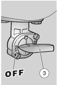
Rotate the key (1) and move the ignition switch (2) to position "X".
Move the fuel tap lever (3) to position "OFF".
Position the vehicle on the stand, see pag. 54 (POSITIONING THE VEHICLE
ON THE STAND).
WARNING
Never leave the key in the ignition switch.
Lock the steering, see pag. 33 (STEERING LOCK) and extract the key.
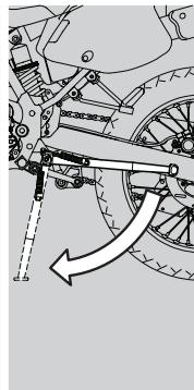
POSITIONING THE VEHICLE ON THE STAND
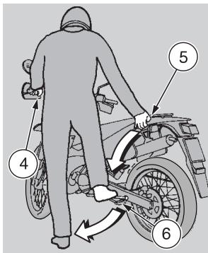
Carefully read beside (PARKING).
Grasp the left grip (4) and the passenger grab rail (5).
Press the side stand with your right foot and extend it completely (6).
Incline the vehicle until the stand rests on the ground.
CAUTION
Make sure that the vehicle is stable.
SUGGESTIONS TO PREVENT THEFT
NEVER leave the ignition key inserted and always use the steering lock.
Park the vehicle in a safe place, possibly in a garage or a protected place.
Make sure that all documents are in order and that the road tax has been paid
Write down your personal data and telephone number in this page, to facilitate the identification of the owner in case of finding after theft.
SURNAME:
NAME:
ADDRESS:
TELEPHONE NO:
CAUTION
Very often stolen vehicles are identified thanks to the data written in the use/maintenance manual.
MAINTENANCE
WARNING
Risk of fire.
Keep fuel and other flammable substances away from the electrical components.
Before beginning any service operations or inspection of the vehicle, switch off the engine and remove the key, wait until the engine and the exhaust system have cooled down and, if possible, lift the vehicles with the proper equipment onto firm and flat ground.
Before proceeding, make sure that the room in which you are working is properly ventilated.
Keep away from the red-hot parts of the engine and of the exhaust system, in order to avoid burns.
CAUTION
Do not hold any mechanical piece or other parts of the vehicle with your mouth: the components are not edible and some of them are noxious or even toxic.
If not expressly indicated otherwise, for the reassembly of the units repeat the disassembly operations in reverse order.
In case any maintenance operation should be required, it is advisable to use latex gloves.
Routine maintenance operations can usually be carried out by the user, but sometimes specific tools and specific technical skills may be required.
In case periodic maintenance operations, assistance or technical advice are needed, contact an Concessionario Ufficiale aprilia, who will ensure you prompt and accurate servicing.
Ask your Concessionario Ufficiale aprilia to test the vehicle on the road after a repair or periodic maintenance operation.
In any case, personally carry out the "Preliminary checking operations" after any maintenance operation, see p. pag. 47 (PRELIMINARY CHECKING OPERATIONS)
REGULAR SERVICE INTERVALS CHART
OPERATIONS TO BE CARRIED OUT BY THE aprilia Official Dealer (WHICH CAN BE CARRIED OUT EVEN BY THE USER).
Key
① = check and clean, adjust, lubricate or change, if necessary;
② = clean;
③ = change;
④ = adjust.
(^*) = Use grease MOLYCOTE 6 Rapidplus
NOTE Perform the maintenance operations with doubled frequency if the vehicle is used in rainy or dusty areas, on uneven surfaces or on racetracks.
| Component | Post running in (after 1 month) or 1000 Km (625 mi) | Every 12 months or 4000 Km (2500 mi) | Every 24 months or 8000 Km (5000 mi) |
| Battery / terminals tightening | ① | ① | - |
| Spark plug | ② | ② | ③ |
| Air cleaner | ① | ② | - |
| Clutch clearance | ④ | ④ | - |
| Light system | ① | ① | - |
| Brake fluid | - | ① | - |
| Coolant | every 3 months: ① | ||
| 2 stroke oil level | Check before each ride: ① | ||
| Transmission oil | ③ | ① | every 12000 Km (7500 mi): E |
| Headlamp beam setting - operation | - | ① | - |
| Start lever pin | - | ① Lubricate with water-repellent grease (*) | - |
| Engine idling rpm | ④ | ① | - |
| Wheels/tyres and inflation pressure | every month: ① | ||
| Drive chain tension and lubrication | every month: ① | ||
| Front and rear brake pads wear | ① | every month: ① | |
OPERATIONS TO BE CARRIED OUT BY THE aprilia Official Dealer.
Key
① = check and clean, adjust, lubricate or change, if necessary (according to workshop manual specifications);
② = clean;
③ = change;
④ = adjust.
NOTE Perform the maintenance operations with doubled frequency if the vehicle is used in rainy or dusty areas, on uneven surfaces or on racetracks.
| Component | Post running in (after 1 month) or 1000 Km (625 mi) | Every 12 months or 4000 Km (2500 mi) | Every 24 months or 8000 Km (5000 mi) |
| Rear shock absorber | - | - | ① |
| Carburettor | - | - | ② |
| Transmission cables and controls | ① | ① | - |
| RAVE control unit FP | ① | - | ④ |
| Wheels balancing | - | ① | - |
| Steering stem bearing and steering play | ① | ① | - |
| Wheel bearings | - | ① | - |
| Brake discs | ① | ① | - |
| Mixer oil filter | - | - | ② |
| Vehicle general operation | ① | ① | - |
| Braking systems | ① | ① | - |
| Cooling system | ① | ① | - |
| Brake fluid | every year: ③ | ||
| Coolant | every 2 years: ③ | ||
| Muffler/exhaust silencer | - | ① | - |
| Fork oil and oil seal | every 2 years: ③ | ||
| Piston and piston rings | every 2 years: ① / every 4 years: ③ | ||
| 2 stroke oil pump and air bleeding | ① | - | ④ |
| Fuel cock | ① | ① | - |
| Wheels/tyres and inflation pressure | ① | ① | - |
| Nut, bolt, screw tightening | ① | ① | - |
| Battery terminals tightening | ① | ① | - |
| 2 stroke oil reserve warning light | ① | ① | - |
| Final tension (chain, front and rear sprockets) | - | ① | - |
| Fuel line | - | ① | every 4 years: ③ |
| Brake hose | - | ① | every 4 years: ③ |
| Mixer oil line | - | ① | every 4 years: ③ |
| Clutch wear | - | ① | - |
| Exhaust valve FP | ① | ② + ④ | every 4 years: ③ |
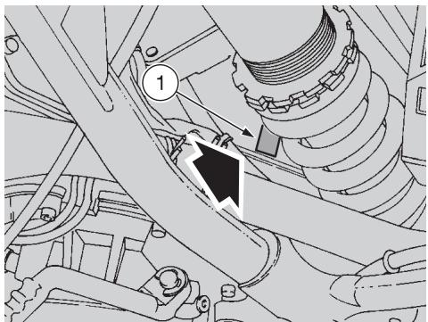
IDENTIFICATION DATA
It is a good rule to write down the frame and engine numbers in the space provided in this manual.
The frame number can be used for the purchase of spare parts.
CAUTION
Do not alter the identification numbers if you do not want to incur severe penal and administrative sanctions. In particular, the alteration of the frame number results in the immediate invalidity of the guarantee.
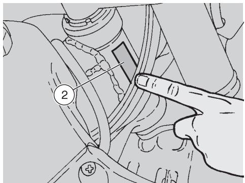
ENGINE NUMBER
The engine number (1) is stamped on the right side of the engine casing base.
Engine no.
FRAME NUMBER
The frame number is stamped on the right side of the steering column.
Frame no.
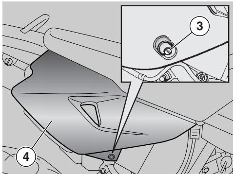
REMOVING THE SIDE COVERS
Carefully read pag. 55 (MAINTENANCE).
Position the vehicle on the stand.
CAUTION
The description of the following operations refers to one side cover, but it is valid for both.
- Rotate the quick fastening screw (3) anticlockwise by giving it 1/4 turn.
WARNING
Proceed with care.
Do not damage the tangs and/or their seats.
Handle the plastic components with care and avoid scraping or damaging them.
Withdraw and remove the side cover (4).
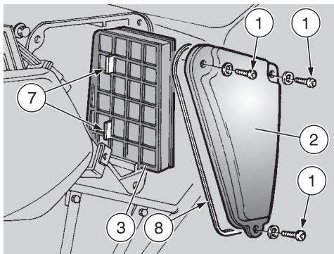
AIR CLEANER
WARNING
Do not use petrol or inflammable solvents to wash the air cleaner, in order to avoid fires or explosions. Carefully read pag. 55 (MAINTENANCE).
Check the conditions of the air cleaner and clean it monthly or every 4000km depending on the conditions in which the vehicle is used. If the vehicle is used on dusty or wet roads, the cleaning operations and any replacement should be carried out more frequently. Before the cleaning operation, it is necessary to remove the air cleaner from the vehicle.
REMOVAL
Remove the right side cover, see pag. 58 (REMOVING THE SIDE COVERS).
Unscrew and remove the three screws (1) and take the relevant washers.
Remove the filter casing cover (2).
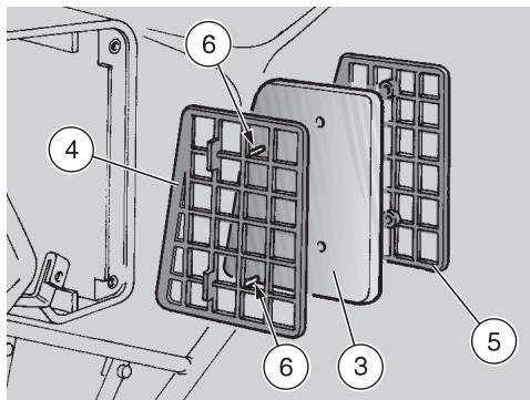
CAUTION
Clean the inside of the filter casing before withdrawing the filtering element, in order to prevent dust and foreign matters from entering the suction manifold.
Clean the inside of the filter casing and of the filter casing cover (2) with a cloth.
Withdraw the filtering element (3) complete with the grids (4) and (5).
CLEANING
WARNING
In order not to deform the grids, DO NOT force their sides.
Grasp the central part of both grids (4) and (5), pull and separate them.
Release the filtering element (3) from the grid (4).
Clean the filtering element (3) with clean, non-inflammable solvents or solvents with high volatility point, then let it dry thoroughly.
Apply a filter oil or a thick oil (SAE 80W-90) on the whole surface of the filtering element, then squeeze it to eliminate the oil in excess.
CAUTION
The filtering element (3) must be well impregnated, though not dripping.
CHANGE
Replace the filtering element (3) with a new one of the same type.
- Check the condition of the gasket (8); if it is damaged, change it.
Upon reassembly:
CAUTION
Be careful to the shape of the filtering element and the grids: they must coincide.
Correctly introduce the filtering element (3) in the two pins (6).
Position the grid (5).
Push both grids in correspondence with the pins (6).
CAUTION
The two protruding elements (7) avoid the incorrect insertion of the filtering element in the filter casing.
Introduce the filtering element, complete with grids, in the filter casing guides.
CHECKING THE TRANSMISSION OIL LEVEL AND TOPPING UP
Carefully read pag. 36 (TRANSMISSION OIL) and pag. 55 (MAINTENANCE).
Check gearbox oil level every 4000km Change gearbox oil at the end of the running in period and every 12000 km afterwards, see pag.61 (CHANGING THE TRANSMISSION OIL).
CHECKING
CAUTION
Position the vehicle on firm and flat ground.
- Stop the engine and let it cool down for at least ten minutes, in order to allow the oil to flow back to the oil pan and to cool down.
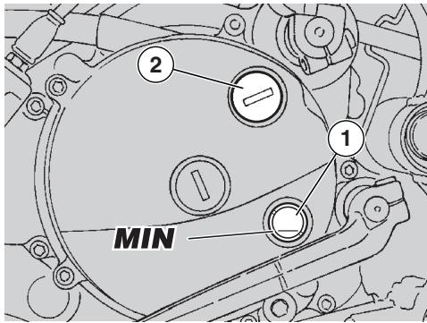
- Keep the vehicle in vertical position, with the two wheels resting on the ground.
CAUTION
The non-performance of the operations described above may result in a wrong measurement of the level.
- Make sure that oil level (1) is above one fourth of the level (MIN).
CAUTION
The oil level must neither exceed a half of the height of the glass, nor fall below one fourth. In the first case the excess oil would flow out of the oil pan; in the second case the engine may get seriously damaged.
TOPPING UP
If it were necessary to top up, proceed as follows:
Unscrew and remove the filling cap (2).
Pour a small quantity of oil see pag. 88 (LUBRICANT CHART), and wait for about one minute to allow the oil to evenly flow inside the casing.
- Make sure that oil level (1) is above one fourth of the level (MIN).
- If the oil level is below the specified limit, top up again with small amounts of oil, and then check oil level again through sight glass (1).
- Once finished, screw and tighten filler cap (2).
WARNING
Tighten the filling cap thoroughly and make sure that there are no oil leaks.
Periodically check that there are no leaks in correspondence with the oil pan cover seal.
Do not use the vehicle with insufficient lubrication or with contaminated or unsuitable lubricants, since this would accelerate the wear of the moving parts and may also cause irreparable failures.
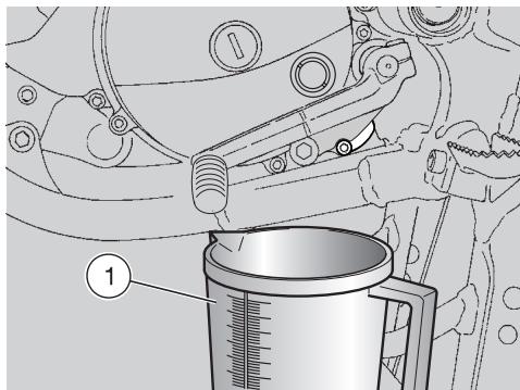
CHANGING THE TRANSMISSION OIL
Carefully read pag. 36 (TRANSMISSION OIL) and pag. 55 (MAINTENANCE).
Check gearbox oil level every 4000km Change gearbox oil at the end of the running in period and every 12000 km afterwards, see pag.61 (CHANGING THE TRANSMISSION OIL).
To change the oil, proceed as follows:
Drive for a few miles, until the engine reaches the normal running temperature.
CAUTION
Position the vehicle on firm and flat ground.
- Stop the engine and let it cool down for at least ten minutes, in order to allow the oil to flow back to the oil pan and to cool down.
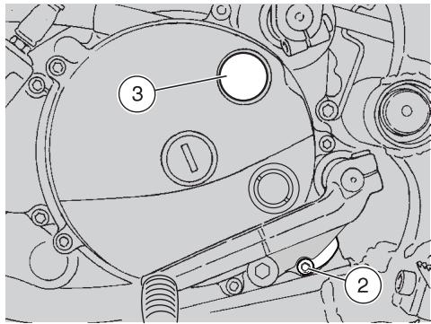
WARNING
When warmed up, the engine contains hot oil; therefore, while carrying out the operations described here below be particularly careful, in order to avoid burns.
Position the vehicle on the stand.
- Put a container (1) with at least 600~cm^3 capacity in correspondence with the drain plug (2).
Unscrew and remove the drain plug (2).
Unscrew and remove the filling plug (3).
Drain the oil and let it drip into the container (1) for a few minutes.
Remove the metal residues from the drain plug (2) magnet.
- Check and if necessary replace the sealing washer of the drain plug (2).
Change the sealing washer of the drain plug (2) every 12000km (or every second engine oil change).
Screw and tighten the drain plug (2).
Drain plug (2) driving torque: 27 Nm (2,7 kgm).
Pour about 550~cm^3 of transmission oil through the filling opening (3), see pag. 88 (LUBRICANT CHART).
Tighten the filling plug (3).
Start the engine, see pag. 48 (STARTING) and let it idle for about one minute, in order to ensure the filling up of the transmission oil circuit.
Check the oil level and top up if necessary, see pag.60 (CHECKING THE TRANSMISSION OIL LEVEL AND TOPPING UP).
WARNING
Tighten the filling cap thoroughly and make sure that there are no oil leaks.
Periodically check that there are no leaks in correspondence with the oil pan cover seal.
Do not use the vehicle with insufficient lubrication or with contaminated or unsuitable lubricants, since this would accelerate the wear of the moving parts and may also cause irreparable failures.
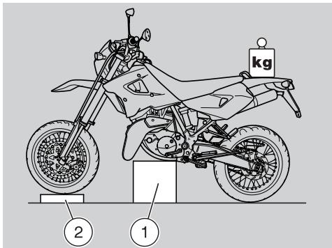
FRONT WHEEL
WARNING
The disassembly and reassembly of the front wheel may be difficult for unskilled operators. If necessary, contact an aprilia Official Dealer.
If you want to perform these operations personally, keep to the following instructions.
Carefully read pag. 55 (MAINTENANCE).
While disassembling and reassembling the wheel, be careful not to damage the brake pipe, the disc and the pads.
Before performing the operations described here below, let the engine and the silencer cool down until they reach room temperature, in order to avoid burns.
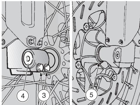
DISASSEMBLY
Position the vehicle on the stand.
WARNING
Due to the weight and dimensions of the vehicle, the following operation cannot be performed by one person only.
Proceed with care and make sure that you can support the weight of the vehicle.
CAUTION
Weight of the vehicle (ready for starting): 126 kg.
- Raise the front part of the vehicle and have a suitable support (1) (the weight of which should be about 400mm ) placed under the engine, so that the front wheel can rotate freely and the vehicle cannot fall down.
WARNING
The vehicle may fall down.
Provide for balancing the vehicle, in order to prevent it from falling down.
Position and secure a weight of about 40 kg to rear end to support vehicle front end.
WARNING
Make sure that the vehicle is stable.
- Put a support (2) under the tyre, in such a way as to keep the wheel in its position after loosening it.
- Have the handlebar held still in driving position, so that the steering is locked.
Loosen the two screws (3) of the wheel pin clamp.
Unscrew the wheel pin (4) completely.
CAUTION
To facilitate the extraction of the wheel pin, slightly lift the wheel.
Support the front wheel and manually withdraw the wheel pin (4).
CAUTION
Check spacer (5) direction so as not to mismatch it at reassembly.
Remove the wheel and carefully withdraw the disc from the brake caliper.
Take the spacer ring (5).
WARNING
Never pull the front brake lever after removing the wheel, otherwise the caliper pistons may go out of their seats, thus causing the outflow of the brake fluid. In this case consult your aprilia Official Dealer, who will carry out the proper maintenance operation.
REASSEMBLY
Carefully read pag. 55 (MAINTENANCE).
WARNING
While reassembling the wheel, be careful not to damage the brake pipe, the disc and the pads.
Position the wheel between the fork rods, on the support (2), without fitting the disc in the brake caliper.
CAUTION
Moderately grease the outer seats of the wheel hub.
Insert the shorter diameter of the spacer ring (5) in the wheel hub seat (left side in the travelling direction).
CAUTION
When fitting the disc in the brake caliper, proceed with care.
- Move the wheel and carefully fit the disc in the brake caliper.
CAUTION
Uniformly apply a moderate quantity of grease on the wheel pin.
- Partially insert the wheel pin (4) from the right side of the vehicle (travelling direction).
Thrust the wheel pin and at the same time move the wheel (in such a way as to align the pin axes and the wheel), until introducing the wheel pin completely.
Screw and tighten the wheel pin (4).
Wheel pin (4) driving torque: 80 Nm (8 kgm).
WARNING
Due to the weight and dimensions of the vehicle, the following operation cannot be performed by one person only.
Proceed with care and make sure that you can support the weight of the vehicle.
CAUTION
Weight of the vehicle (ready for starting): 126 kg.
- Raise the front part of the vehicle and remove the support positioned under the engine during disassembly.
Lower the vehicle and position it on the stand.
With pulled front brake lever, press the handlebar repeatedly, thrusting the fork downwards. In this way the fork rods will settle properly.
Tighten the two wheel pin clamp screws (3).
Wheel pin clamp screw (3) driving torque: 10 Nm (1 kgm).
WARNING
After reassembly, pull the front brake lever repeatedly and check the correct functioning of the braking system.
Check the wheel centering.
Have the driving torques, centering and balancing of the wheel checked by your aprilia Official Dealer, in order to avoid accidents that may be harmful for you and/or other people.
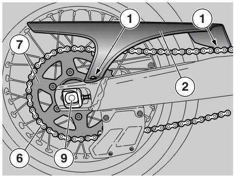
REAR WHEEL
WARNING
The disassembly and reassembly of the rear wheel may be difficult for unskilled operators. If necessary, contact an aprilia Official Dealer.
If you want to perform these operations personally, keep to the following instructions.
Carefully read pag. 55 (MAINTENANCE).
Before carrying out the following operations, let the engine and the silencer cool down until they reach room temperature, in order to avoid burns.
While disassembling and reassembling the wheel, be careful not to damage the brake pipe, the disc and the pads.
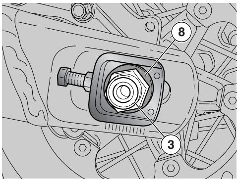
WARNING
For the disassembly and reassembly, use gloves in order to protect your hands and fingers properly.
Riding with damaged rims may be dangerous for the rider, other persons and the vehicle.
Check the conditions of the wheel rim and change it if it is damaged.
DISASSEMBLY
Position the vehicle on the stand.
Loosen and remove the two screws (1).
Remove the chain casing (2).
Loosen the wheel nut (3).
Wheel nut (3) driving torque: 100 Nm (10 kgm).
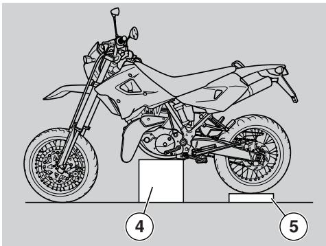
WARNING
Upon reassembly, before tightening the wheel nut (3), check the chain tension, see pag. 66 (DRIVE CHAIN).
Due to the weight and dimensions of the vehicle, the following operation cannot be performed by one person only.
Proceed with care and make sure that you can support the weight of the vehicle.
CAUTION
Weight of the vehicle (ready for starting): 126 kg.
- Raise the rear part of the vehicle, have a suitable support (4) (the height of which should be 400mm ) placed under the engine, so that the rear wheel can rotate freely and the vehicle cannot fall down.
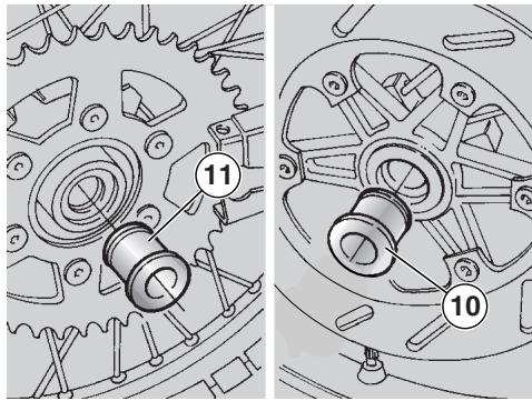
WARNING
The vehicle may fall down.
Provide for balancing the vehicle, in order to prevent it from falling down.
Make sure that the vehicle is stable.
Place a support (5) under the tyre, in such a way as to keep the wheel in the correct position after releasing it.
CAUTION
Lower the drive chain (6) outside the crown gear (7).
WARNING
Do not introduce your fingers between the chain and the crown gear.
Move the wheel completely forward; release the drive chain from above, rotating the rear wheel anticlockwise.
CAUTION
Upon reassembly, introduce the drive chain from below, rotating the rear wheel in the travelling direction.
- Unscrew and remove the wheel nut (3) and take the washer (8).
CAUTION
To facilitate the extraction of the wheel pin, slightly raise the wheel.
- Hold the rear wheel and manually withdraw the wheel pin (9).
CAUTION
The left (10) and right spacer rings (11) remain positioned in the respective seats on the wheel; if they should come off, reposition them correctly (see REASSEMBLY).
- Withdraw the wheel from the rear fork from behind, carefully withdrawing the disc from the brake caliper.
WARNING
Never pull the rear brake lever after removing the wheel, otherwise the caliper piston may go out of its seat, thus causing the outflow of the brake fluid. In this case consult your aprilia Official Dealer, who will carry out the proper maintenance operation.
CAUTION
Left (10) and right (11) spacers remain into their seats on the wheels; if they come off, reposition them correctly (see REASSEMBLY).
Take the left spacer ring (10).
Take the right spacer ring (11).
Upon reassembly:
Moderately grease the outer seats of the wheel hub.
Fit the spacer rings (10) (11) with the longer diameter towards the outside of the vehicle.
Uniformly apply a moderate quantity of grease on the wheel pin.
WARNING
After reassembly, pull the rear brake lever repeatedly and check the correct functioning of the braking system.
Check the wheel centering.
Have the driving torques, centering and balancing of the wheel checked by your aprilia Official Dealer, in order to avoid accidents that may be harmful for you and/or other people.
Check chain tension.
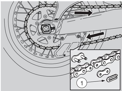
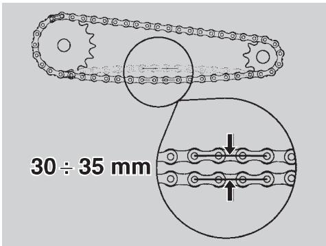
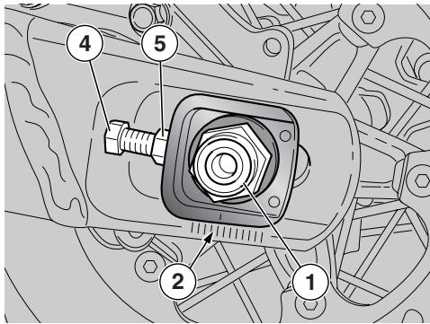
DRIVE CHAIN
Carefully read pag. 55 (MAINTENANCE).
The vehicle is equipped with a chain with ring link joint.
In case of disassembly and reassembly of the chain, make sure that the clip (1) of the ring link joint has its open side opposite the travelling direction (see figure).
WARNING
An excessive slackening of the chain can cause it to come off of the sprockets, which often results in accidents or serious damage to the vehicle. Periodically check the slack and adjust it if necessary, see pag. 67 (ADJUSTMENT).
To change the chain, contact an Concessionario Ufficiale aprilia, who will ensure you prompt and accurate servicing.
WARNING
Incorrect maintenance may cause the untimely wear of the chain and/or damages to the pinion and/or the crown.
Carry out the maintenance operations more frequently if you use the vehicle in difficult conditions or on dusty and/or muddy roads.
CHECKING THE SLACK
To check the slack, proceed as follows:
Stop the engine.
Position the vehicle on the stand.
Position the shifting lever in neutral.
Make sure that the vertical oscillation, in an intermediate point between pinion and crown in the lower part of the chain, is about 30 ÷ 35 ~mm .
- Move the vehicle forwards, or turn the wheel, in order to be able to check the vertical oscillation of the chain even when the wheel turns; the slack must be constant in all the rotation phases of the wheel.
WARNING
If in some positions the slack is higher than in others, this means that there are crushed or seized links; in this case, contact an aprilia Official Dealer.
To prevent the risk of seizures, lubricate the chain frequently, see pag. 67 (LUBRICATION AND CLEANING).
If the slack is uniform, but higher or lower than 30 ÷ 35 ~mm , adjust it, see pag. 67 (ADJUSTMENT).
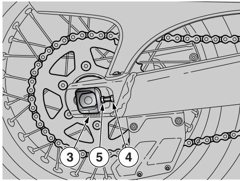
ADJUSTMENT
If after the check it is necessary to adjust the chain tension, proceed as follows:
Raise vehicle on stand.
Fully loosen nut (1).
NOTE Some fixed reference marks (2-3), positioned inside the chain tensioner sliding shoes on the swinging arms on wheel shaft front side, are used for wheel truing up.
Loosen the two check nuts (4).
Turn adjusters (5) to set chain play, making sure that the same reference marks (2-3) are matching on both sides of the vehicle.
Tighten the two check nuts (4).
Tighten nut (1).
Wheel nut (1) tightening torque: 100 Nm (10 kgm).
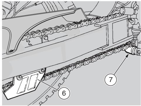
Check chain play pag. 66 (CHECKING THE SLACK).
CHECKING THE WEAR OF CHAIN, PINION AND CROWN
Further, check the chain and sprockets and make sure that they do not present:
Damaged rollers.
Loose pins.
Dry, rusty, crushed or seized links.
Excessive wear.
Lacking O rings.
- Sprocket or teeth excessively worn or damaged.
WARNING
If the chain rollers are damaged, the pins are loose and/or the O rings are damaged or lacking, it is necessary to change the whole chain unit (both sprockets and chain).
- Check the wear of U-shaped chain guide (6) and of the chain tightening roller (7).
- Finally, check the wear of the rear fork protection shoe.
WARNING
Lubricate the chain frequently, especially if there are dry or rusty parts. The crushed or seized links must be lubricated and made work again. If this is not possible, contact an aprilla Official Dealer, who will provide for changing the chain.
LUBRICATION AND CLEANING
WARNING
Carry out the adjustment, lubrication, cleaning and change of the chain with great care.
Lubricate the chain every 500km or whenever necessary.
Lubricate the chain with spray grease for chains only, see pag. 88 (LUBRICANT CHART).
Never wash the chain with water jets, steam jets, high-pressure water jets and highly inflammable solvents.
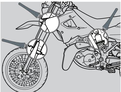
INSPECTING THE FRONT AND REAR SUSPENSIONS
WARNING
Have the front fork oil changed by an aprilia Official Dealer, who will ensure you prompt and accurate servicing.
Carefully read pag. 55 (MAINTENANCE).
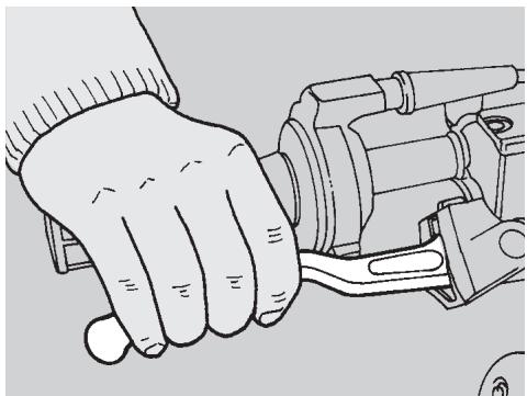
Change front fork oil every 15,000 km or every 2 years.
Check the oil every 8000 km and change it if it is dirty.
Change the fork oil more frequently if the vehicle is used on dusty or wet roads or off road.
Further, carry out the following checking operations:
With pulled front brake lever, press the handlebar repeatedly, thrusting the fork downwards.
The stroke must be gentle and there must be no trace of oil on the rods.
- Check the fastening of all the components and the functionality of the front and rear suspension joints.
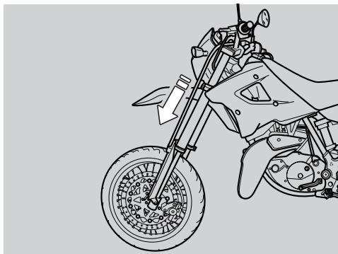
WARNING
If you notice irregularities in the operation or if the help of a qualified technician is necessary, contact your aprilia Official Dealer.
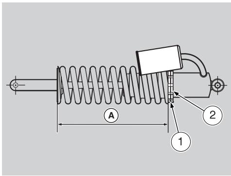
REAR SUSPENSION
The rear suspension consists of a springshock absorber unit, fixed to the frame by means of silent-blocks and to the rear fork by means of lever systems.
To change vehicle trim, set spring preload (A) as follows: loosen the locking (2) and turn the adjusting ring (1)
Standard setting: 245~mm
Max. pre-load: 240 mm.
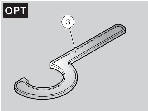
ADJUSTING THE REAR SHOCK ABSORBER PRELOAD
The standard setting of the rear shock absorber is such as to satisfy most driving conditions at low and high speed, either with reduced load and full load.
However, it is also possible to adjust the setting according to the intended use of the vehicle.
Slightly unscrew the locking ring nut (2) by means of the appropriate spanner (3) OPT.
Act on the adjusting ring nut (1) (shock absorber spring preload adjustment) (see figure).
- Once the optimal attitude has been obtained, tighten the locking ring nut (2) completely.
| Adjusting ring nut (1) | By screwing it | By unscrewing it |
| Function | Spring preload increase | Spring preload decrease |
| Attitude | The vehicle is more rigid | The vehicle is less rigid |
| Recommended kind of road | Smooth or normal roads | Roads with uneven surface |
| Notes | Rider and passenger | Solo rider |
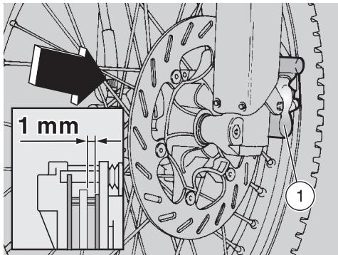
The following information refers to a single braking system, but are valid for both.
Check brake pads wear at the end of the running-in period or after the first 1,000km and then every 4,000km .
The wear is greater when the vehicle is used on dusty or wet roads and off road

WARNING
Check the brake pads before every trip.
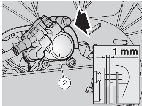
To carry out a rapid checking of the wear of the pads, proceed as follows:
Position the vehicle on the stand.
Carry out a visual checking between the brake caliper and the pads.Proceed:
- from the front upper part for the front brake caliper (1);
from the rear upper part for the rear brake caliper (2).
- If the thickness of the friction material (even of one pad only) has reduced to about 1mm , replace both pads.

WARNING
Have the pads changed by your aprilia Official Dealer.
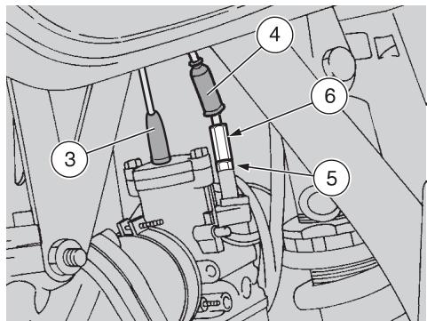
ADJUSTING THE COLD START CONTROL (1)
Leggere attentamente Carefully read pag. 55 (MAINTENANCE).
The ideal slack of the cold start control should be about 2 ÷ 3 ~mm .
To adjust the slack, proceed as follows:
Position the vehicle on the stand.
Move to the left side of the vehicle.

CAUTION
DO NOT withdraw the accelera-tor cable protection element (3).
Withdraw the protection element (4).
Loosen the nut (5)(by screwing it).
Act on the adjuster (6) positioned on the carburettor.
After the adjustment:
Tighten the nut (5) (by turning it anticlockwise), thus locking the adjuster (6) and put back the protection element (4).
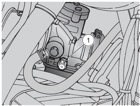
IDLING ADJUSTMENT
Carefully read pag. 55 (MAINTENANCE).
Adjust idle speed at the end of running-in period and, anyway, whenever necessary. To carry out this operation, proceed as follows:
Drive for a few miles until the engine reaches the normal running temperature, then stop the engine.
Position the vehicle on the stand.
CAUTION
Work on the right side of the vehicle.
Connect an electronic revolution counter to the spark plug cable.
Start the engine.
The minimum speed of the engine (idling) must be about 1500 ± 100 rpm.
If necessary:
Act on the adjusting screw (1) positioned on the carburettor.
By SCREWING IT (clockwise), you increase the engine rpm.
By UNSCREWING IT (anticlockwise), you decrease the engine rpm.
Twist the throttle grip, accelerating and decelerating a few times to make sure that it functions correctly and to check if the idling speed is constant.
CAUTION
Do not act on the air adjusting screw, to avoid variations of the carburation setting.
WARNING
If necessary, contact your aprilia Official Dealer.
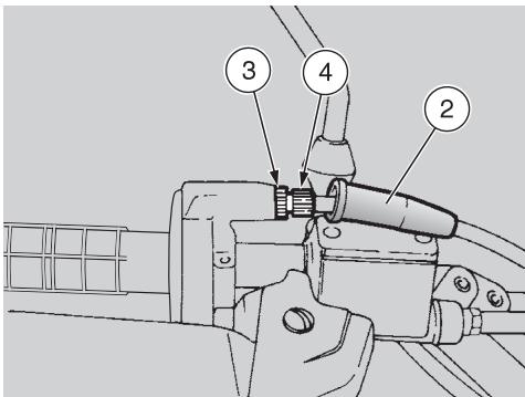
ADJUSTING
THE ACCELERATOR CONTROL
Carefully read pag. 55 (MAINTENANCE).
The ideal slack of the accelerator control should be about 2-3 mm.
To adjust the slack, proceed as follows:
Position the vehicle on the stand.
Remove the protection element (2).
Loosen the nut (3) (by turning it clockwise).
Act on the adjuster (4), positioned at the beginning of the accelerator control cable.
After the adjustment:
- Tighten the nut (3) (by turning it anticlockwise), thus locking the adjuster (4) and put back the protection element (2).
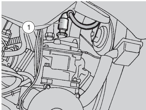
SPARK PLUG
Carefully read pag. 55 (MAINTENANCE).
Check spark plug wear at the end of the running-in period, and then every 4,000 km. Change it every 8,000 km.
Periodically remove the spark plug and clean it carefully, removing carbon deposits; change it if necessary.
To reach the spark plug:
Position the vehicle on the stand.
CAUTION
Work on the right side of the vehicle.
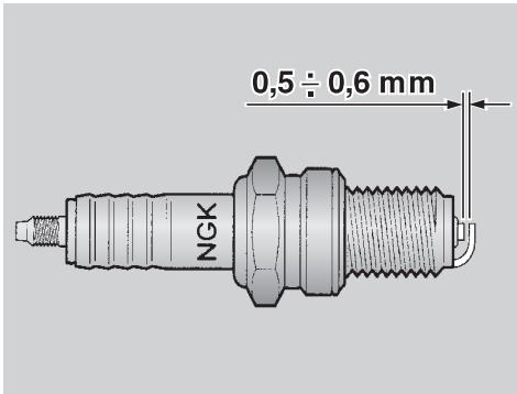
To remove and clean the spark plug:
Take off the spark plug cap (1).
- Remove all the dirt from the base of the spark plug, then unscrew it with the spanner you will find in the tool kit and extract it from its seat, taking care that neither dust nor other substances enter the cylinder.
- Make sure that there are neither carbon deposits, nor corrosion marks on the electrode and on the central porcelain part; if necessary, clean them with the special cleaners for spark plugs, with an iron wire and/ or a metal brush.
- Energetically blow some air, in order to prevent the removed residues from getting into the engine.
If the spark plug has crackings on the insulating material, corroded electrodes or excessive deposits, it must be changed.
- Check the spark plug gap with a thickness gauge.
The gap must be 0.5 ÷ 0.6 mm , if necessary adjust it, carefully bending the earth electrode. - Make sure that the washer is in good conditions. With the washer on, screw the spark plug by hand in order not to damage the thread.
- Tighten the spark plug by means of the spanner you will find in the tool kit, giving it half a turn to compress the washer.
Spark plug driving torque: 20 Nm (2 kgm).
WARNING
The spark plug must be well tightened, otherwise the engine may overheat and be seriously damaged.
Use the recommended type of spark plug only, see pag. 85 (TECHNICAL DATA), in order not to compromise the life and performance of the engine.
Position the spark plug cap (1) correctly, so that it does not come off due to the engine vibrations.
BATTERY
Carefully read pag. 55 (MAINTENANCE).
Check electrolyte level and battery terminals tightening at the end of the running-in period, and then every 4,000 km or 6 months.
WARNING
The electrolyte in the battery is toxic and caustic and if it gets in contact with the skin it can cause burns, since it contains sulphuric acid.
Wear protection clothes, a face mask and/or goggles during maintenance operations.
In case of contact with the skin, rinse with plenty of water.
In case of contact with the eyes, rinse with plenty of water for 15 minutes, then consult an oculist without delay.
If the electrolyte is accidentally swallowed, drink a lot of water or milk, then continue drinking milk of magnesia or vegetable oil and consult a doctor without delay.
The battery gives off explosive gases; keep it away from flames, sparks, cigarettes and any other source of heat. During the recharging or the use, make sure that the room is properly ventilated and avoid inhaling the gases released during the recharging.
KEEP AWAY FROM CHILDREN
WARNING
Never invert the connection of the battery cables.
Do not incline the vehicle too much, in order to avoid dangerous leaks of the battery fluid.
Connect and disconnect the battery with the ignition switch in position " 念 . Connect first the positive cable (+) and then the negative cable (-)
Disconnect following the reverse order.
The electrolyte is corrosive.
Do not pour or spill it, especially on the plastic parts.

LONG INACTIVITY OF THE BATTERY
If the vehicle remains unused for a long period:
Remove the battery, see pag. 74 (REMOVING THE BATTERY) and put it in a cool and dry place.
Recharge it completely, by using a trickle charge, see pag. 75 (RECHARGING THE BATTERY).
If the battery remains on the vehicle, disconnect the cables from the terminals.
It is important to check the charge periodically (about once a month), during the winter or when the vehicle remains unused, in order to prevent the deterioration of the battery.
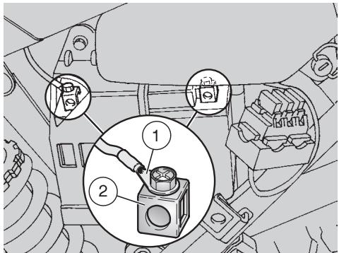
CHECKING AND CLEANING THE TERMINALS
Carefully read p. 73 (BATTERY).
Remove the left side cover, see pag. 58 (REMOVING THE SIDE COVERS).
Make sure that the cable terminals (1) and the battery terminals (2) are:
- in good conditions (and not corroded or covered with deposits);
covered with special grease or Vaseline.
If necessary:
Remove the battery, see beside (REMOVING THE BATTERY).
Eliminate any sign of corrosion with a wire brush.
Reconnect first the positive (+) and then the negative cable (-) .
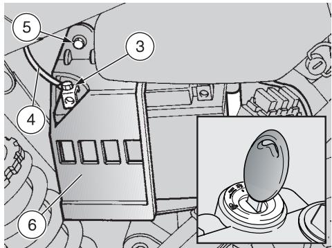
Cover the terminals with special grease or Vaseline.
Reinstall the battery, see p. 57 (INSTALLING THE BATTERY).
REMOVING THE BATTERY
Carefully read p. 73 (BATTERY).
Make sure that the ignition switch is in position "X".
Remove the left side cover, see pag. 58 (REMOVING THE SIDE COVERS).
Unscrew and remove the screw (3) from the negative terminal (-) .
Move the negative cable (-) (4) sideways.
Unscrew and remove the screw (5).
Remove the cover (6).
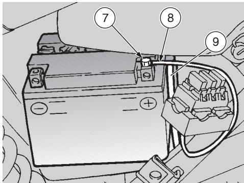
- Partially remove the battery from its compartment.
Unscrew and remove the screw (7) from the positive terminal (+) .
Move the positive cable (+) (8) sideways.
Withdraw the breather pipe(9).
WARNING
Once it has been removed, the battery must be stored in a safe place and kept away from children.
- Remove the battery from its compartment and put it on a flat surface, in a cool and dry place.
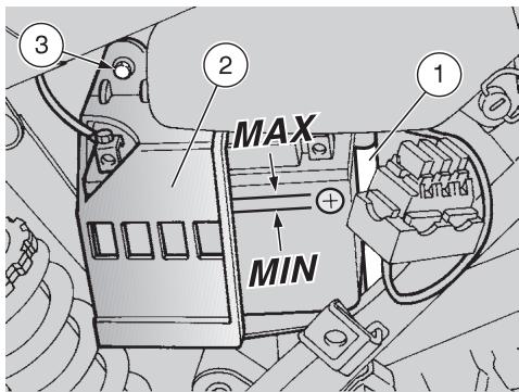
CHECKING THE ELECTROLYT E LEVEL
Carefully read pag. 73 (BATTERY).
CAUTION
Position the vehicle on firm and flat ground.
Remove the left side cover, see pag. 58 (REMOVING THE SIDE COVERS).
- Keep the vehicle in vertical position, with the two wheels resting on the ground.
CAUTION
Failure to perform the operations described above may lead to the wrong measurement of the level.
- Make sure that the fluid level is included between the two "MIN" and "MAX" notches stamped on the battery side.
Otherwise:
Remove the battery from its compartment, see pag. 74 (REMOVING THE BATTERY).
Unscrew and remove the element plugs.
WARNING
Top up with distilled water only. Do not exceed the "MAX" mark, since the electrolyte level increases during the recharge.
Top up by adding distilled water.
RECHARGING THE BATTERY
Carefully read pag. 73 (BATTERY).
Remove the battery from its compartment, see pag. 74 (REMOVING THE BATTERY).
Unscrew and remove the element plugs.
Check the electrolyte level, vedi sopra (CHECKING THE ELECTROLYTE LEVEL).
Connect the battery with a battery charger.
A recharge with an amperage equal to 1/10th of the battery capacity is recommended.
After the recharging operation, check the electrolyte level again and if necessary top up with distilled water.
Replace the element plugs.
WARNING
Reinstall the battery only 5-10 minutes after disconnecting the recharge equipment, since the battery keeps sending out extremely inflammable hydrogen gas for a short lapse of time.
INSTALLING THE BATTERY
Carefully read pag. 73 (BATTERY).
Connect the breather pipe (1).
WARNING
Always connect the battery breather pipe, to prevent the sulphuric acid vapours from corroding the electric system, painted parts, rubber elements or gaskets when they exit the breather pipe itself.
Connect, in order, the positive (+) and negative (-) cable.
Cover the terminals with special grease or Vaseline.
Put the battery in its container.
Put back the cover (2).
Screw and tighten the screw (3).
Put back the left side cover, see pag. 58 (REMOVING THE SIDE COVERS).
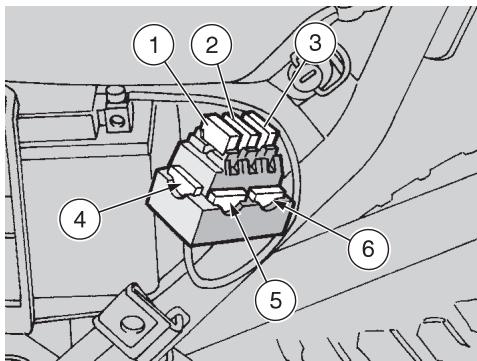
CHANGING THE FUSES
Carefully read pag. 55 (MAINTENANCE).
WARNING
Do not repair faulty fuses. Never use fuses different from the recommended ones.
The use of unsuitable fuses may cause damages to the electric system or, in case of short circuit, even a fire.
CAUTION
If a fuse blows frequently, there probably is a short circuit or an overload in the electric system. In this case it is advisable to consult an aprilia Official Dealer.

If an electric component does not work or works irregularly, or if the vehicle fails to start, it is necessary to check the fuses.
For the checking, proceed as follows:
Turn the ignition switch to position "×", to avoid any accidental short circuit.
Remove the left side cover, see pag. 58 (REMOVING THE SIDE COVERS).
Extract the fuses one by one and check if the filament (7) is broken.
Before replacing a fuse, try to find out the cause of the trouble, if possible.
Replace the damaged fuse with a new one having the same amperage.
CAUTION
If you use one of the spare fuses (4) (5) (6), put a new fuse in the proper seat.
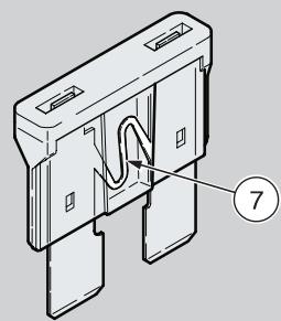
ARRANGEMENT OF THE FUSES
20A fuse (1)
From the battery to: ignition switch, voltage regulator.
15A fuse (2)
From the ignition switch to: all light loads and horn.
7,5A fuse (3)
From ignition switch to: ignition.
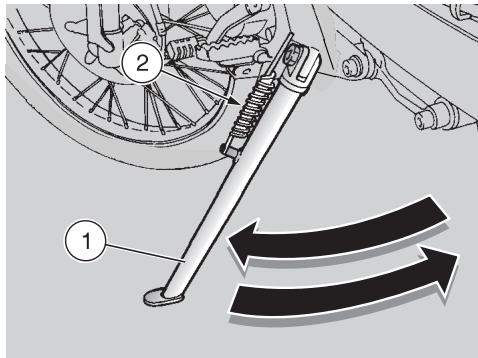
CHECKING THE SIDE STAND AND THE SAFETY SWITCH
CAUTION
The vehicle is equipped with automatic folding stand.
Carefully read pag. 55 (MAINTENANCE) and pag. 77 (CHECKING THE SWITCHES).
The side stand (1) must rotate without hindrances.
Carry out the following checks:
The springs (2) must not be damaged, worn, rusty or weakened.
- The side stand must rotate freely, if necessary grease the joint, see pag. 88 (LUBRICANT CHART).
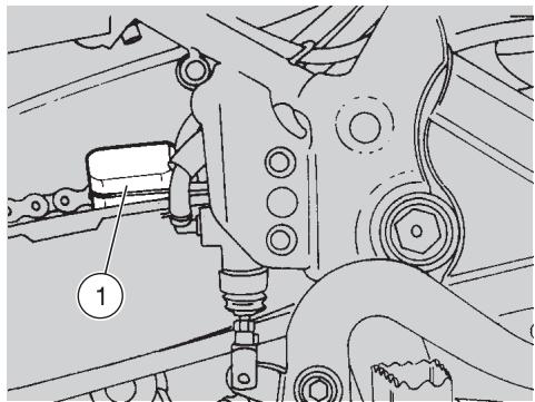
CHECKING THE SWITCHES
Carefully read pag. 55 (MAINTENANCE).
The vehicle is fitted with two switches:
Stoplight switch (1) on the rear brake control lever.
Stoplight switch (2) on the front brake control lever.
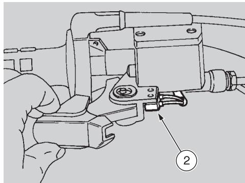
Checking:
- Switches (1) and (2): withdraw the protection element.
- Make sure that there are neither dirt, nor mud deposits on the switch.
- Make sure that the cables are connected correctly.
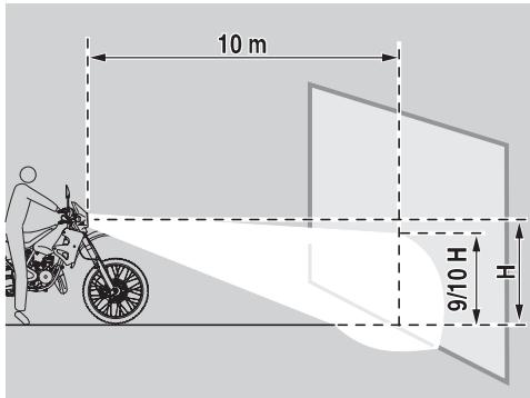
ADJUSTING THE VERTICAL HEADLIGHT BEAM
To rapidly check the correct direction of the beam, place the vehicle on flat ground, 10m away from a wall.
Turn on the low beam, sit on the vehicle and make sure that the beam projected on the wall is slightly under the horizontal line of the headlight (about 9/10th of the total height).
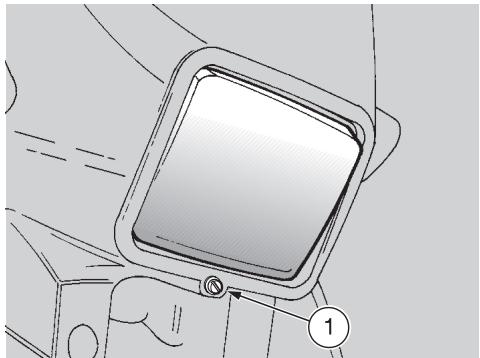
To adjust the headlight beam:
Act on the suitable screw (1) by means of a screwdriver.
By TURNING IT CLOCKWISE, you set the beam upwards.
By TURNING IT ANTICLOCKWISE, you set the beam downwards.
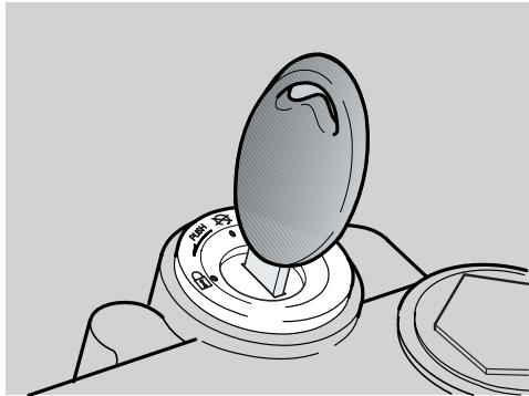
BULBS
Carefully read pag. 55 (MAINTENANCE).
WARNING
Before changing a bulb, position the vehicle on the stand and move the ignition switch to position "X".
Change the bulb wearing clean gloves or using a clean and dry cloth.
Do not leave fingerprints on the bulb, since these may cause its overheating and consequent breakage.
If you touch the bulb with bare hands, remove any fingerprint with alcohol, in order to prevent it from blowing frequently.
DO NOT FORCE THE ELECTRIC CABLES
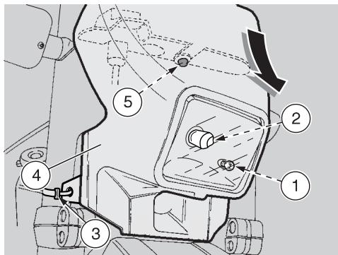
CHANGING THE HEADLIGHT BULBS
Carefully read pag. 78 (BULBS).
CAUTION
Before changing a bulb, check the fuses, see pag. 76 (CHANGING THE FUSES).
The flashlight contains:
A parking light bulb (1).
A low beam/high beam bulb (halogenous) (2).
To change the bulbs, proceed as follows:
WARNING
The front part of the fairing (4), complete with the headlight, remains connected to the electric wires; do not pull them.
Remove the two ties (3), used to secure
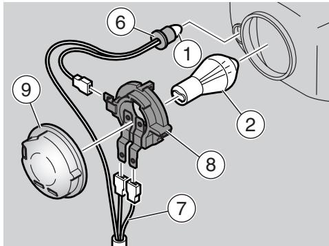
front fairing to frame, from forks.
WARNING
Handle the plastic components with care and avoid scraping or damaging them.
- Withdraw the front part of the fairing (4), complete with the headlight, downwards and disconnect it from the pin (5) provided on the dashboard.
PARKING LIGHT BULB
CAUTION
To extract the bulb socket, do not pull its electric wires.
Grasp the bulb socket (6), pull and disconnect it from its seat.
- Withdraw the parking light bulb (1) and replace it with one of the same type.
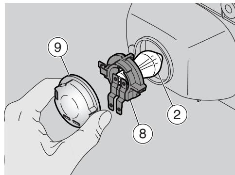
LOW / HIGH BEAM BULB (HALOG-ENOUS)
CAUTION
To extract the bulb electric connector, do not pull its electric wires.
Grasp the bulb electric connector (7), pull it and disconnect it from the bulb (8).
Remove housing (9) from reflector and from bulb terminals
Turn bulb holder (8) anticlockwise to remove it from reflector
Remove bulb (2) from its location
For the installation:
NOTE Insert the bulb in the bulb socket, making the relevant positioning seats coincide.
Position bulb holder (6) into reflector and turn it clockwise.
Correctly install housing (9) inside bulb terminals and reflector.
Connect bulb (7) connector.
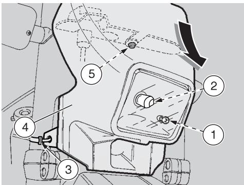
CHANGING THE DASHBOARD BULBS
Carefully read pag. 78 (BULBS).
CAUTION
Before changing a bulb, check the fuses, see pag. 76 (CHANGING THE FUSES).
The dashboard contains:
The warning light bulbs.
- The dashboard lighting bulb.
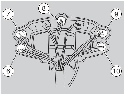
To change the bulbs, proceed as follows:
WARNING
The front part of the fairing (2), complete with headlight, remains connected to the electric wires; do not pull them.
Unscrew and remove the two screws (1).
CAUTION
Handle the plastic components with care and avoid scraping or damaging them.
- Withdraw the front part of the fairing (2), complete with headlight, downwards and disconnect it from the pin (3) provided on the dashboard.
WARNING LIGHT BULBS
WARNING
Extract the bulb sockets one by one, in order not to position them incorrectly upon reassembly.
Extract the corresponding bulb socket:
| Pos. | Warning light | Colour |
| 6 | 2 stroke oil reserve (∞) | red |
| 7 | Direction indicators (◇⇒) | green |
| 8 | Neutral indicator (N) | green |
| 9 | Low beam (IDL) | green |
| 10 | High beam (IDL) | blue |
- Withdraw the bulb and replace it with a new one of the same type.
DASHBOARD LIGHTING BULB
Extract the bulb socket (9).
- Withdraw the bulb and replace it with a new one of the same type.
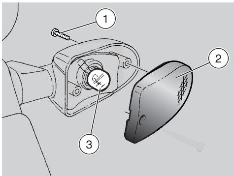
CHANGING THE FRONT AND REAR DIRECTION INDICATORS
Carefully read pag. 78 (BULBS).
CAUTION
Before changing a bulb, check the fuses, see pag. 76 (CHANGING THE FUSES).
Unscrew and remove the screw (1).
WARNING
Upon reassembly, tighten the screw (1) carefully and moderately, in order not to damage the protection screen.
Remove the protection screen (2).
Press the bulb (3) slightly and rotate it anticlockwise.
Extract the bulb from its seat.

CAUTION
Insert the bulb in the bulb socket, making the two pins coincide with the relevant guides on the bulb socket.
Correctly install a new bulb of the same type.
CHANGING THE REAR LIGHT BULB
WARNING
Before changing a bulb, check the fuses, see pag. 76 (CHANGING THE FUSES) and the efficiency of the stoplight switches, see pag. 77 (CHECKING THE SWITCHES).
Carefully read pag. 78 (BULBS).
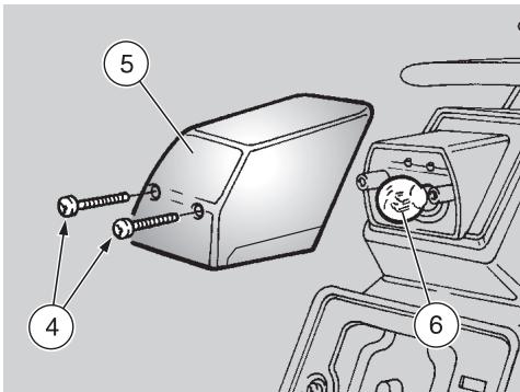
Unscrew and remove the two screws (4).
WARNING
Upon reassembly, tighten the two screws (4) carefully and moderately, in order not to damage the protection screen.
Remove the protection screen (5).
Press the bulb (6) slightly and rotate it anticlockwise.
Extract the bulb from its seat.
CAUTION
Insert the bulb in the bulb socket, making the two pins coincide with the relevant guides on the bulb socket.
Correctly install a new bulb of the same type.
CAUTION
Before transporting the vehicle, it is necessary to empty the fuel tank and the carburettor carefully, see below (DRAINING THE FUEL TANK), making sure that they are completely dry.
During transport the vehicle must be kept in vertical position, in order to avoid any oil, coolant and battery fluid leakage.
The vehicle must be firmly anchored with the 1st gear on.
WARNING
In case of failure, do not tow the vehicle, but have it moved by a maintenance vehicle.
DRAINING THE FUEL TANK
Carefully read pag. 36 (FUEL).
WARNING
Risk of fire.
Wait until the engine and the exhaust silencers have completely cooled down.
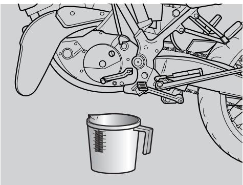
WARNING
Fuel vapours are noxious for your health.
Before proceeding, make sure that the room in which you are working is properly ventilated.
Do not inhale fuel vapours.
Do not smoke, nor use free flames.
Do not dispose of fuel in the environment.
Position the vehicle on the stand.
- Stop the engine and wait until it has cooled down.
Prepare a container with capacity exceeding the fuel quantity present in the tank and put it on the ground on the left side of the vehicle.
Remove the fillercap.

Empty the fuel tank by means of a manual pump or a similar system.
WARNING
After draining the tank, tighten the fillercap.
To drain the carburettor completely, proceed as follows:
Position the fuel tap (1) on "RES".
Start the vehicle, see pag. 48 (STARTING).
Accelerate a few times, until the engine stops due to lack of fuel.
If necessary, contact an aprilia Official Dealer.
CLEANING
Clean the vehicle frequently if it used in particular areas or conditions, such as:
- Polluted areas (cities and industrial areas).
- Areas characterized by an high percentage of salinity and humidity (sea areas, hot and humid climates).
- Particular conditions (use of salt and anti-ice chemical products on the roads during the winter).
Avoid leaving deposits of industrial and polluting powders, tar spots, dead insects, bird droppings, etc. on the body. - Avoid parking the vehicle under trees, since in some seasons residues, resins, fruits or leaves fall down, which contain substances that may damage the paint.
WARNING
After the vehicle has been washed, its braking functions could be temporarily impaired because of the presence of water on the grip surfaces. Calculate long braking distances to avoid accidents. Brake repeatedly to restore normal conditions.
Carry out the preliminary checking operations, see p. pag. 47 (PRELIMINARY CHECKING OPERATIONS).
To remove dirt and mud from the painted surfaces use a low- pressure water jet, carefully wet the dirty parts, remove mud
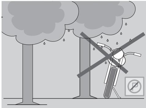
impregnated with a lot of water and shampoo (2÷ 4% parts of shampoo in water).
Then rinse with plenty of water and dry with chamois leather.
To clean the outer parts of the engine use a degreaser, brushes and wipers.
CAUTION
Polish with silicone wax only after having carefully washed the vehicle.
Do not wash the vehicle under the sun, especially during the summer, when the body is still warm, since if the shampoo dries before being rinsed away, it can damage the paint.
Use neither high pressure water/air jets, nor vapour jets on the following parts: wheel hubs, controls on the right and on the left side of the handlebar, brake
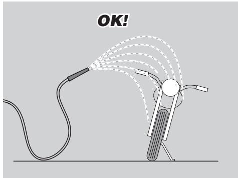
silencer exhaust, glove/tool kit compartment, ignition switch/steering lock.
CAUTION
Do not use alcohol or solvents to clean the rubber and plastic parts and the saddle: use water and mild soap.
Do not apply protection waxes onto the saddle, in order not to make it too slippery.

LONG PERIODS OF INACTIVITY
After a long period of inactivity of the vehicle some precautions are necessary to avoid any problem.
Further, it is important to carry out the necessary repairs and a general check up before the period of inactivity, since you could forget to carry them out later.
Proceed as follows:
Drain the fuel tank and the carburettor completely, see pag. 82 (DRAINING THE FUEL TANK).
Remove the spark plug, see p. 54 (SPARK PLUG).
- Pour a teaspoon (5 ÷ 10 ~cm^3) of engine oil into the cylinder.
Rotate the ignition switch (1) to position "X".
Press the start lever (2) a few times, to distribute the oil evenly on the cylinder surfaces.
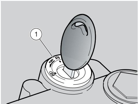
Reinstall the spark plug, see pag. 72 (SPARK PLUG).
Remove the battery, see pag. 74 (REMOVING THE BATTERY).
Wash and dry the vehicle, see pag. 83 (CLEANING).
Polish the painted surfaces with wax.
Inflate the tyres, see pag. 43 (TYRES).
By means of a suitable support, position the vehicle so that both tyres are raised from the ground.
Place the vehicle in an unheated, nothumid room, away from sunlight, with minimum temperature variations.
Cover the vehicle avoiding the use of plastic or waterproof materials.
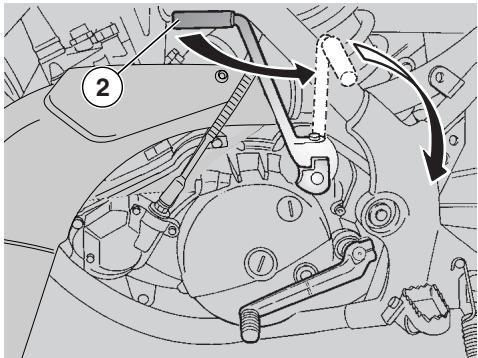
AFTER A PERIOD OF INACTIVITY
Uncover and clean the vehicle, see pag. 83 (CLEANING).
- Check the electrolyte level in the battery and install it, see pag. 75 (CHECKING THE ELECTROLYT E LEVEL) and pag. 75 (INSTALLING THE BATTERY).
Refill the fuel tank, see pag. 36 (FUEL).
Carry out the preliminary checking operations, see pag. 47 (PRELIMINARY CHECKING OPERATIONS).
WARNING
Have a test ride at moderate speed in a low-traffic area.
TECHNICAL DATA
| DIMENSIONS | Max. length (with rear mudguard extension) | 2165 mm |
| Max. width | 840 mm | |
| Max. height (front part of the fairing included) | 1170 mm | |
| Seat height | 870 mm | |
| Distance between centres | 1480 mm | |
| Min. ground clearance | 290 mm | |
| Weight ready for starting | 126 kg | |
| ENGINE | Type | One-cylinder, 2-stroke with laminar suction. Separate lubrication with variable strength automatic mixer (1.0 - 3.0%). |
| Number of cylinders | 1 | |
| Total displacement | 124.82 cm³ | |
| Bore / stroke | 54 mm / 54.5 mm | |
| Compression ratio | 12.5 ± 0.5 : 1 | |
| Starting | with pedal | |
| Engine idling rpm | 1200 ± 100 rpm | |
| Clutch | multidisc in oil bath, with manual control on the left side of the handlebar. | |
| Cooling | liquid-cooled | |
| CAPACITY | Fuel (reserve included) | 11 l |
| Fuel reserve | 1.3 l (mechanical reserve) | |
| Transmission oil | 600 cm³ | |
| Coolant | 0.8 l (50% water + 50% antifreeze with ethylene glycol) | |
| 2 stroke oil (reserve included) | 1.25 l | |
| 2 stroke oil reserve | 0.5 l | |
| Seats | 2 | |
| Vehicle max. load (driver + passenger + luggage) | 336 kg |
TRANSMISSION Type mechanical, 6 gears with foot control on the left side of the engine
| GEAR RATIOS | Ratio | Primary | Secondary | Final ratio | Total ratio |
| 1st | 19/63 = 1 : 3.315 | 10 / 30 = 1 : 3.000 | 16 / 45 = 1 : 2.81 | R1 x R2 x R3 = 1 : 27.976 | |
| 2nd | 14 / 29 = 1 : 2.071 | R1 x R2 x R3 = 1 : 19.317 | |||
| 3rd | 17 / 27 = 1 : 1.588 | R1 x R2 x R3 = 1 : 14.81 | |||
| 4th | 19 / 25 = 1 : 1.316 | R1 x R2 x R3 = 1 : 12.270 | |||
| 5th | 21 / 23 = 1 : 1.095 | R1 x R2 x R3 = 1 : 10.213 | |||
| 6th | 22 / 21 = 1 : 0.954 | R1 x R2 x R3 = 1 : 8.901 |
CARBURETTORS Number 1 Model DELL'ORTO PHBH 28
FUEL SUPPLY Fuel unleaded petrol according to the DIN 51607 standard, min. O.N. 95 (N.O.R.M.) and 85 (N.O.M.M.)
FRAME Type One-beam with two cradles in high-resistance steel tubes Steering inclination angle 28° Fore stroke 127 mm
SUSPENSIONS Front. Upside down 040 Stroke. 260 mm Rear. Gas-filled monoshock Stroke. 280 mm
BRAKES Front. Disc brake - 0 320 mm - with hydraulic transmission Rear. Disc brake - 0 220 mm - with hydraulic transmission
WHEEL RIMS Type Spoke aluminium Front. 3,00× 17^ Rear. 4,25× 17^
| TYRES | FRONT | 110/70 ZR 17 54W |
| Inflation pressure for solo rider: | 180 kPa (1,8 bar) | |
| Inflation pressure for rider and passenger: | 180 ± 10 kPa (1,8 ± 0,1 bar) | |
| REAR | 150/60 ZR 17 66W | |
| Inflation pressure for solo rider: | 200 kPa (2 bar) | |
| Inflation pressure for rider and passenger: | 230 ± 10 kPa (2,3 ± 0,1 bar) | |
| IGNITION | Type | CDI |
| Spark advance | 12° ± 2° before T.D.C. | |
| SPARK PLUG | Standard | NGK R BR8 ES |
| Spark plug gap | 0.5÷0.6 mm | |
| ELECTRIC | Battery | 12 V - 4 Ah |
| SYSTEM | Fuses (general) | 20 A |
| Fuses (control unit) | 15 A | |
| Fuses (service) | 7,5 A | |
| Generator | 12 V - 180 W | |
| BULBS | Low/high beam | 12 V - 35/35 W |
| Front parking light | 12 V - 5 W | |
| Direction indicators | 12 V - 10 W | |
| Rear parking light/number plate light/ stoplight | 12 V - 5 / 21 W | |
| Dashboard | 12 V - 2 W | |
| WARNING LIGHTS | Neutral | 12 V - 1.2 W |
| Direction indicators | 12 V - 1.2 W | |
| High beam | 12 V - 1.2 W | |
| 2 stroke oil reserve | 12 V - 1.2 W | |
| Low beam | 12 V - 1.2 W |
LUBRICANT CHART
Gearbox oil (recommended): F.C., SAE 75W - 90 or Agip GEAR SYNTH, SAE 75W - 90.
As an alternative to the recommended oil, it is possible to use high-quality oils with characteristics in compliance with or superior to the A.P.I. GL-4 specifications.
Mixer oil (recommended): MAX 2T COMPETITION or Agrip SPEED 2T.
As an alternative to the recommended oil, use high-quality oils with characteristics in compliance with or superior to the ISO-L-ETC++, A.P.I. TC++ specifications.
Fork oil (recommended): F.A. 5W or F.A. 20W; an alternative Agip FORK 5W or Agip FORK 20W fork oil.
If you need an oil with intermediate characteristics in comparison with the F.A. 5W and F.A. 20W or Agp FORK 5W and Agip FORK 20W, these can be mixed as indicated below:
SAE 10W = F.A. 5W 67% of the volume + F.A. 20W 33% of the volume, or Agip FORK 5W 67% of the volume + Agip FORK 20W 33% of the volume.
SAE 15W = F.A. 5W 33% of the volume + F.A. 20W 67% of the volume, or Agip FORK 5W 33% of the volume + Agip FORK 20W 67% of the volume.
Bearings and other lubrication points (recommended): AUTOGREASE MP or Agrip GREASE 30.
As an alternative to the recommended product, use high-quality grease for rolling bearings, working temperature range -30^ +140^ , dripping point 150^ ... 230^ , high protection against corrosion, good resistance to water and oxidation.
Protection of the battery poles: neutral grease or vaseline.
Spray grease for chains (recommended): CHAIN SPRAY or Agp CHAIN LUBE.
WARNING
Use new brake fluid only. Employer uniquely du liquide a freins neuf. Do not mix different makes or types of oil without having checked bases compatibility.
Brake fluid (recommended): F.F., DOT 4 (DOT 5 compatible) or Agip BRAKE 5.1 DOT 4 (DOT 5 compatible).
WARNING
Use only antifreeze and anticorrosive without nitrite, ensuring protection at -35^ at least.
Engine coolant (recommended): ECOBLU - 40°C or Agip COOL.
THE VALUE OF SERVICE
aprilia
Thanks to ongoing technical updates and product-specific technical training, aprilia Authorised Network engineers are familiar with every detail of this motorcycle and have the special equipment required for correct maintenance and repair.
A vehicle kept in sleek running order is a reliable vehicle. Pre-ride checks, proper maintenance at the recommended intervals and using aprilia Original Parts only are other key factors!
To find contact information of the Authorised Dealer and/or Service Centre nearest you, please consult the Yellow Pages or the map provided at our web site:
www.aprilia.com
When you demand aprilia Original Parts, you are purchasing products that have been developed and tested as early as the vehicle design stage. aprilia Original Parts systematically undergo strict quality control procedures to ensure total reliability and long service life.

MOTOMAX MOTORLU ARACLAR SAN.VETIC.A.S.
Kore Sehitleri Cad. No. 42 - 80300 - Zincirlikuyu - Istanbul
Tel. 0090-212-3360058 - Fax. 0090-212-3360057 - Email:sule@interline.com.tr

MILLE MOTOR KFT. (sede operativa)
Hold utca 23 - H-1054 - Budapest
Tel. 0036-1-3329938 - Fax. 0036-1-2693044 - Email: Zsoldos.lajos@elender.hu

MILFA IMPORTACAO EXPORTACAO LDA.
Av. Da Republica 692 - 4450 - Matosinhos
Tel. 00351-229382450 - Fax. 00351-229371305 - Email: milfa@milfa.pt

APRILIA HELLAS
Rizareiou 4 - 15233 - Halandri
Tel. 0030-210-6898290 - Fax. 0030-210-6898056 - Email: aprilia@otermail.gr

MOHAG A.G.
Bernerstrasse Nord 202 - 8064 - Zurigo
Tel. 0041-1-4348686 - Fax 0041-1-434 8606 - Email: agonser@mohag.ch

N.V./S.A. RAD
Landegemstraat 4 - Industriegebied - B-9031 - Drongen-Baarle Tel. 0032-9-2829410 - Fax. 0032-9-2810012 - Email: aprilia@rad.be

T.M.P.
Hammervej 32 - 7900 - Nikobing Mors
Tel. 0045-97-722233 - Fax. 0045-97-722143/33 - Email: thomas@aprilia.dk

TUONTI NAKKILA OY
P.o.B. 18 - 29250 - Nakkila
Tel. 00358-2-5352500 - Fax. 00358-2-5372793 - Email: satu.saarinen@aprilia.fi

RO GROUP INT.(sede operativa)
Str. Depozitelor 41-43 Jud. Arges - Pitesti
Tel. 0040-248211004 -Fax. 0040-248211004 - Email: marian.ion@rogroup.ro

Z.A.O. ITALMOTO (sede operativa)
Ul. Preobragenskaya 5/7 - 107076 - Mo - Moscow
Tel. 007-095-780 4294 - Fax. 007-095-208 3228 - Email: italmoto@mtu-net.ru

APRILIA U.S.A., INC. (Sede operativa)
109 Smoke Hill Lane Suite 190 - GA 30188 - Woodstock
Tel. 001-770-592-2261 - Fax. 001-770-592-4878

APRILIA JAPAN CORP.
SHINYOKOHAMAMEGURO BLDG. 3-22-5 SHINYOKOHAMA KOUHOKU-KU 222-0033
YOKOHAMA-SHI KANAGAWA (J) -Tel. 0081-454772632 - Fax 0081-454772605 - Email: m-okuyama@apriliajapan.co.jp

JOHN SAMPLE GROUP PTY LTD.
8 Sheridan Close - NSW 2214 - Milperra - Sydney
Tel. 0061-2-97722666 - Fax. 0061-2-97742321 - Email: doreilly@jsg.com.au

No. 281 Jungshing North Street - Sanchung City - 241 - Taipei
Tel. 00886-2-85111156 - Fax: 00886 2 85111148 - Email: taiwan.eisyu @ msa.hinet.net

AL-RADWAN INTERNATIONAL GROUP
Block 1, Street 13, Plot 107 45703 - Shuwaikh Industrial
Tel. 00965-4828072 - Fax. 00965-4828073 - Email: zed@zedmotorz.com

ACCESS INTERNATIONAL FOR TRADING SARL.
Diamond Tower, 10th Floor P.O.B. 13 - Verdun, near Mandarine Beirut
Tel. 00961-1797333 - Fax: 00961-1798333 - Email: access_in@ hotmail.com

PT. MOTOR MEGA PERFORMA
aprilia s.p.a. wishes to thank its customers for the purchase of this vehicle.
- Do not dispose of oil, fuel, polluting substances and components in the environment.
- Do not keep the engine running if it isn't necessary.
- Avoid disturbing noises.
- Respect nature.
- KINΔYNOΣ
- PPOsOXH
- PPOZOXH
- AAYIAMA METAOESH
- PYOMIISH IPOΦOPTIeH ΠIeΩ AMOPTIeP
- PYOMISH XEIPISTHPIOY EKKINHSE ME KPYO (N)
- H AEA THS TEXNIKHES YIIOESTHPIEH
- aprilia
- www.aprilia.com
- SAFETYWARNINGS
- WARNING
- CAUTION
- TECHNICAL INFORMATION
- WARNING - PRECAUTIONS - GENERAL ADVICE
- VERSION:
- SAFETY RULES
- CLOTHING
- ACCESSORIES
- LOAD
- KEY
- INSTRUMENTS AND INDICATORS TABLE
- MULTIFUNCTION COMPUTER
- START-UP SETTING
- Metric system setting (KM/H or MPH)
- Setting the "WS" wheel diameter
- Pre-set value 1850.
- Time setting
- Preventative lubrication check
- Preventative maintenance check
- Checking the total distance covered (ODO)
- Checking the total race time (ART)
- Programming the second vehicle
- STANDARD SETTING
- DISABLING THE SCHEDULED MAINTENANCE SERVICES
- CHRONOMETER
- RESETTING THE PARTIAL VALUES
- ALIGNING THE PARTIAL VALUES (TRIP)
- BACKLIGHTING
- CHANGING THE BATTERY
- CONTROLS ON THE LEFT SIDE OF THE HANDLEBAR
- IGNITION SWITCH
- STEERING LOCK
- OPERATION
- GLOVE/TOOL KIT COMPARTMENT
- CRASH HELMET HOOK
- SPECIAL TOOLS OPT
- FUEL
- KEEP AWAY FROM CHILDREN
- TRANSMISSION OIL
- STROKE OIL TANK
- BRAKE FLUID - recommendations
- DISC BRAKES
- FRONT BRAKE
- REAR BRAKE
- ADJUSTING
- ADJUSTING THE CLUTCH
- TYRES
- COOLANT
- SILENCER
- INSTRUCTIONS FOR USE
- STARTING
- Starting with flooded engine
- Starting with cold engine
- If the engine starts
- If the engine does not start
- STARTING AFTER A LONG PERIOD OF INACTIVITY
- DEPARTURE AND DRIVE
- To leave:
- RUNNING-IN
- STOPPING
- PARKING
- POSITIONING THE VEHICLE ON THE STAND
- SUGGESTIONS TO PREVENT THEFT
- MAINTENANCE
- REGULAR SERVICE INTERVALS CHART
- OPERATIONS TO BE CARRIED OUT BY THE aprilia Official Dealer.
- IDENTIFICATION DATA
- ENGINE NUMBER
- FRAME NUMBER
- REMOVING THE SIDE COVERS
- REMOVAL
- CHANGE
- CHECKING THE TRANSMISSION OIL LEVEL AND TOPPING UP
- TOPPING UP
- CHANGING THE TRANSMISSION OIL
- FRONT WHEEL
- DISASSEMBLY
- The vehicle may fall down.
- Make sure that the vehicle is stable.
- REAR WHEEL
- DRIVE CHAIN
- CHECKING THE SLACK
- ADJUSTMENT
- CHECKING THE WEAR OF CHAIN, PINION AND CROWN
- INSPECTING THE FRONT AND REAR SUSPENSIONS
- REAR SUSPENSION
- ADJUSTING THE REAR SHOCK ABSORBER PRELOAD
- ADJUSTING THE COLD START CONTROL (1)
- IDLING ADJUSTMENT
- THE ACCELERATOR CONTROL
- SPARK PLUG
- Carefully read pag. 55 (MAINTENANCE).
- Spark plug driving torque: 20 Nm (2 kgm).
- BATTERY
- LONG INACTIVITY OF THE BATTERY
- CHECKING AND CLEANING THE TERMINALS
- REMOVING THE BATTERY
- CHECKING THE ELECTROLYT E LEVEL
- RECHARGING THE BATTERY
- INSTALLING THE BATTERY
- CHANGING THE FUSES
- ARRANGEMENT OF THE FUSES
- 20A fuse (1)
- 15A fuse (2)
- 7,5A fuse (3)
- CHECKING THE SIDE STAND AND THE SAFETY SWITCH
- CHECKING THE SWITCHES
- ADJUSTING THE VERTICAL HEADLIGHT BEAM
- BULBS
- CHANGING THE HEADLIGHT BULBS
- CHANGING THE DASHBOARD BULBS
- WARNING LIGHT BULBS
- DASHBOARD LIGHTING BULB
- CHANGING THE FRONT AND REAR DIRECTION INDICATORS
- CHANGING THE REAR LIGHT BULB
- DRAINING THE FUEL TANK
- CLEANING
- LONG PERIODS OF INACTIVITY
- AFTER A PERIOD OF INACTIVITY
- TECHNICAL DATA
- LUBRICANT CHART
- THE VALUE OF SERVICE
Brand : APRILIA
Model : MX 125
Category : Motorcycle