
3901 - Power Tools MAKITA - Free user manual and instructions
Find the device manual for free 3901 MAKITA in PDF.

| Product type | Biscuit joiner (lamella joiner) |
| Brand | MAKITA |
| Model | 3901 |
| Maximum cutting depth | 20 mm (25/32\") |
| No-load speed | 10,000 rpm |
| Overall length | 307 mm (12-1/16\") |
| Net weight | 2.8 kg (6.1 lbs) |
| Power source | Mains (with power cord) |
| Switch type | Slide switch with lock-on |
| Depth adjustment | 6 preset positions (0, 10, 20, S, D, MAX) |
| Angle guide | Adjustable height with graduated scale |
| Front plate | Tilts from 0° to 45° with positive stops at 0°, 45°, 90° |
| Blade capacity | Biscuit blades or circular saw blade (Ø 110 mm) optional |
| Dust extraction system | Vacuum adapter with included dust bag |
| Included accessories | Dust bag, lock nut wrench, angle guide, fixing plate |
| Maintenance | Brush replacement, regular cleaning |
| Safety | Blade guard, arbor lock, switch lock-off |
| Warranty | 1 year against manufacturing defects and material defects |
Frequently Asked Questions - 3901 MAKITA
User questions about 3901 MAKITA
0 question about this device. Answer the ones you know or ask your own.
Ask a new question about this device
Download the instructions for your Power Tools in PDF format for free! Find your manual 3901 - MAKITA and take your electronic device back in hand. On this page are published all the documents necessary for the use of your device. 3901 by MAKITA.
USER MANUAL 3901 MAKITA
MANUEL D'INSTRUCTION
For your personal safety, READ and UNDERSTAND before using.
SAVE THESE INSTRUCTIONS FOR FUTURE REFERENCE.
AVERTISSEMENT:
- Due to our continuing programme of research and development, the specifications herein are subject to change without notice.
Note: Specifications may differ from country to country.
GENERAL SAFETY RULES
GEA001-3
WARNING:
Read all instructions. Failure to follow all instructions listed below may result in electric shock, fire and/or serious injury. The term "power tool" in all of the warnings listed below refers to your mains-operated (corded) power tool or battery-operated (cordless) power tool.
SAVE THESE INSTRUCTIONS
Work area safety
- Keep work area clean and well lit. Cluttered and dark areas invite accidents.
- Do not operate power tools in explosive atmospheres, such as in the presence of flammable liquids, gases or dust. Power tools create sparks which may ignite the dust or fumes.
- Keep children and bystanders away while operating a power tool. Distractions can cause you to lose control.
Electrical safety
- Power tool plugs must match the outlet. Never modify the plug in any way. Do not use any adapter plugs with earthed (grounded) power tools. Unmodified plugs and matching outlets will reduce risk of electric shock.
- Avoid body contact with earthed or grounded surfaces such as pipes, radiators, ranges and refrigerators. There is an increased risk of electric shock if your body is earthed or grounded.
-
Do not expose power tools to rain or wet conditions. Water entering a power tool will increase the risk of electric shock.
-
Do not abuse the cord. Never use the cord for carrying, pulling or unplugging the power tool. Keep cord away from heat, oil, sharp edges or moving parts. Damaged or entangled cords increase the risk of electric shock.
- When operating a power tool outdoors, use an extension cord suitable for outdoor use. Use of a cord suitable for outdoor use reduces the risk of electric shock.
Personal safety
- Stay alert, watch what you are doing and use common sense when operating a power tool. Do not use a power tool while you are tired or under the influence of drugs, alcohol or medication. A moment of inattention while operating power tools may result in serious personal injury.
- Use safety equipment. Always wear eye protection. Safety equipment such as dust mask, non-skid safety shoes, hard hat, or hearing protection used for appropriate conditions will reduce personal injuries.
- Avoid accidental starting. Ensure the switch is in the off-position before plugging in. Carrying power tools with your finger on the switch or plugging in power tools that have the switch on invites accidents.
- Remove any adjusting key or wrench before turning the power tool on. A wrench or a key left attached to a rotating part of the power tool may result in personal injury.
- Do not overreach. Keep proper footing and balance at all times. This enables better control of the power tool in unexpected situations.
- Dress properly. Do not wear loose clothing or jewellery. Keep your hair, clothing, and gloves away from moving parts. Loose clothes, jewellery or long hair can be caught in moving parts.
- If devices are provided for the connection of dust extraction and collection facilities, ensure these are connected and properly used. Use of these devices can reduce dust-related hazards.
Power tool use and care
- Do not force the power tool. Use the correct power tool for your application. The correct power tool will do the job better and safer at the rate for which it was designed.
- Do not use the power tool if the switch does not turn it on and off. Any power tool that cannot be controlled with the switch is dangerous and must be repaired.
- Disconnect the plug from the power source and/or the battery pack from the power tool before making any adjustments, changing accessories, or storing power tools. Such preventive safety measures reduce the risk of starting the power tool accidentally.
- Store idle power tools out of the reach of children and do not allow persons unfamiliar with the power tool or these instructions to operate the power tool. Power tools are dangerous in the hands of untrained users.
- Maintain power tools. Check for misalignment or binding of moving parts, breakage of parts and any other condition that may affect the power tools operation. If damaged, have the power tool repaired before use. Many accidents are caused by poorly maintained power tools.
- Keep cutting tools sharp and clean. Properly maintained cutting tools with sharp cutting edges are less likely to bind and are easier to control.
- Use the power tool, accessories and tool bits etc. in accordance with these instructions and in the manner intended for the particular type of power tool, taking into account the working conditions and the work to be performed. Use of the power tool for operations different from those intended could result in a hazardous situation.
Service
- Have your power tool serviced by a qualified repair person using only identical replacement parts. This will ensure that the safety of the power tool is maintained.
- Follow instruction for lubricating and changing accessories.
- Keep handles dry, clean and free from oil and grease.
GEB020-1
Specific Safety Rules
DO NOT let comfort or familiarity with product (gained from repeated use) replace strict adherence to plate joiner safety rules. If you use this tool unsafely or incorrectly, you can suffer serious personal injury.
- Blades must be rated for at least the speed recommended on the tool. Blades running over rated speed can fly apart and cause injury.
- Always use the guard. The guard protects the operator from broken blade fragments and unintentional contact with the blade.
- Hold power tools by insulated gripping surfaces when performing an operation where the cutting tool may contact hidden wiring or its own cord. Contact with a "live" wire will make exposed metal parts of the tool "live" and shock the operator.
- Use only the blades specified for this tool.
- Never operate the tool with the blade locked in exposed position or without the blade cover secured properly in place.
- Make sure that the blade slides smoothly before operation.
- Check the blades carefully for cracks or damage before operation. Replace cracked or damaged blades immediately.
- Make sure that the flange fits in the arbor hole when installing the blade.
- Inspect for and remove all nails or foreign matter from the workpieces before operation.
- Always place the workpieces on a stable workbench.
- Secure the workpieces firmly with clamp or vise.
- NEVER wear gloves during operation.
- Hold the tool firmly with both hands.
- Keep your hands and body away from the cutting area.
- Run the tool for a while without the blade pointing toward anybody. Watch for vibration or wobbling that could indicate poor installation or a poorly balanced blade.
- Never reach your hands underneath the workpieces while the blade is rotating.
- Do not leave the tool running unattended.
- Always be sure that the tool is switched off and unplugged before making any adjustments or replacing the blade.
-
Some material contains chemicals which may be toxic. Take caution to prevent dust inhalation and skin contact. Follow material supplier safety data.
-
Do not use blunt or damaged blades.
- Do not use the tool with damaged guards.
SAVE THESE INSTRUCTIONS.
WARNING:
MISUSE or failure to follow the safety rules stated in this instruction manual may cause serious personal injury.
SYMBOLS
USD201-2
The followings show the symbols used for tool.
V.....volts
A .amperes
Hz.....hertz
...alternating current
no load speed
回 .Class II Construction
.../min.......revolutions or reciprocation per minute
FUNCTIONAL DESCRIPTION
CAUTION:
Always be sure that the tool is switched off and unplugged before adjusting or checking function on the tool.
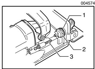
Adjusting the depth of cut
- Pointer
- Stopper
- Adjusting screw
6 cutting depths can be preset according to the size of biscuit to be used or if trimming the wall or ceiling panels as explained later. Rotate the stopper until the pointer points to the appropriate size marked on the stopper.
Refer to the table below for the correspondence between the sizes marked on the stopper and the biscuit size. Fine adjustments to the cutting depth can be made by turning the adjusting screw after loosening the hex nut. This may become necessary after the blade has been resharpened a few times.
006423
| Size on stopper | 0 | 10 | 20 | S | D | MAX |
| Biscuit size | 0 | 10 | 20 | — | — | — |
| Depth of cut | 8 mm (5/16") | 10 mm (0.4") | 12.3mm (0.48") | 13 mm (0.51") | 14.7mm (0.58") | 20 mm (0.8") |
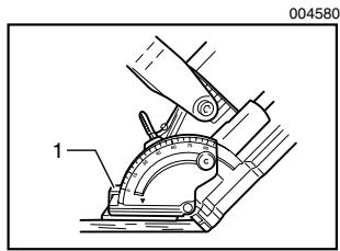
Angle guide
The angle guide can be moved up and down to adjust the position of the blade in relation to the top of the workpiece.
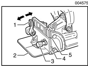
- Lock lever
- Angle guide
- Knob
- Scale
- Pointer
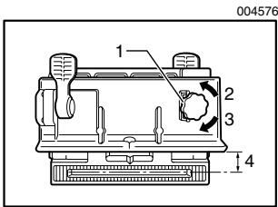
To adjust the angle guide height, loosen the lock lever down and rotate the knob until the pointer points to the desired scale graduation marked on the angle guide. Then tighten the lock lever up to secure the angle guide. The scale on the angle guide indicates the distance from the top of the workpiece to the center of the blade thickness.
004576
- Knob
- Down
3.Up - Center of blade thickness
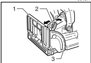
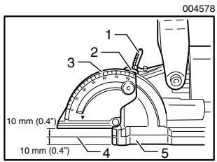
Fence
The angle of the fence can be adjusted between 0^ and 90^ (positive stops at 0^ , 45^ and 90^ ). To adjust the angle, loosen the lock lever and tilt the fence until the pointer points to the desired graduation on the angle scale. Then tighten the lock lever to secure the fence.
004577
- Fence
- Lock lever
- Angle scale
When the fence is set at 90^ , both the distance from the center of the blade thickness to the fence and the distance from the center of the blade thickness to the bottom of the base are 10mm(0.4^ )
Set plate
Use the set plate as shown in the figures when cutting slots in thin workpieces.
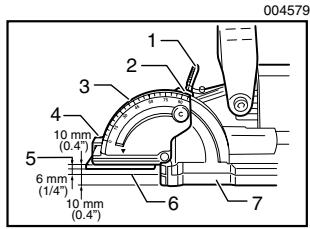
- Lock lever
- Pointer
- Angle scale
- Set plate
- Thickness of set plate
- Center of blade thickness
- Base
- Set plate
Switch action
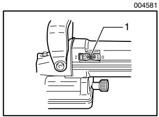
- Slide switch
CAUTION:
- Before plugging in the tool, always check to see that the slide switch actuates properly and returns to the "OFF" position when the rear of the slide switch is depressed.
- Switch can be locked in "ON" position for ease of operator comfort during extended use. Apply caution when locking tool in "ON" position and maintain firm grasp on tool.
To start the tool, slide the slide switch toward the "I (ON)" position. For continuous operation, press the front of the slide switch to lock it.
To stop the tool, press the rear of the slide switch, then slide it toward the "O (OFF)" position.
ASSEMBLY
CAUTION:
Always be sure that the tool is switched off and unplugged before carrying out any work on the tool.
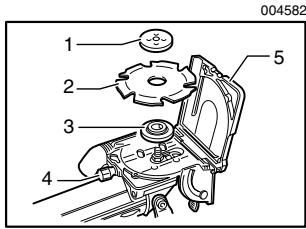
Removing or installing the blade
004582
- Lock nut
- Cutter blade
- Inner flange
- Clamp screw
- Blade cover
CAUTION:
- When installing the cutter blade, mount the inner flange with the side marked "22" facing toward you.
- When installing the circular saw blade, mount the inner flange with the side marked "22" facing toward the tool.
To remove the blade, loosen the clamp screw and open the blade cover. Push the shaft lock and loosen the lock nut using the lock nut wrench. To install the blade, first mount the inner flange.
Then mount the blade and the lock nut. Securely tighten the lock nut using the lock nut wrench. Close the blade cover and tighten the clamp screw to secure the blade cover.
CAUTION:
- Use only Makita lock nut wrench provided to remove or install the blade.
Always check the depth of cut after replacing the blade. Reajust it if necessary.
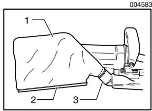
Dust bag
583
- Dust bag
- Fastener
- Dust nozzle
To attach the dust bag, fit it onto the dust nozzle. If the dust bag becomes an obstacle to your work, turn the dust nozzle to change the dust bag position.
When the dust bag is about half full, switch off and unplug the tool. Remove the dust bag from the tool and pull the bag's fastener out. Empty the dust bag by tapping it lightly to remove as much of the dust as possible.
NOTE:
- If you connect a Makita vacuum cleaner to your plate joiner, more efficient and cleaner operations can be performed.
OPERATION
How to make joints
To make joints, proceed as follows:
- Fit the two workpieces together as they will appear in the finished joint position.
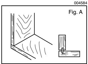
Corner Joint (Fig. A)
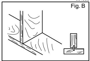
T-Butt Joint (Fig. B)
004585
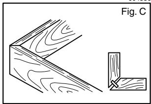
Miter Joint (Fig. C)
004586
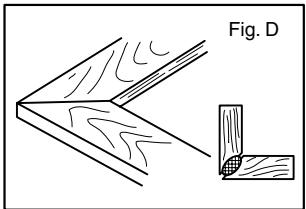
Frame Joint (Fig. D)
004587
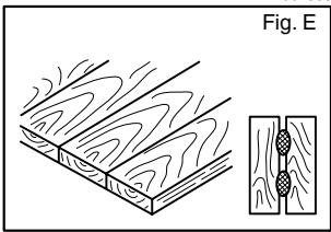
Edge-To-Edge Joint (Fig. E)
004588
- Mark the center of the intended biscuit slots on the workpiece using a pencil.
NOTE:
The center of slots should be at least 50mm (2^ ) from the outer edge of the workpieces.
Allow 100mm - 150mm (4^ - 6^ ) between slots in multiple biscuit application.
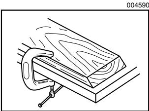
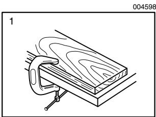
3. For Corner Joint and T-Butt Joint only
Clamp the vertical workpiece to the workbench.
004589
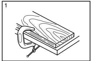
For Miter Joint only
Clamp one workpiece to the workbench with the mitered edge facing up.
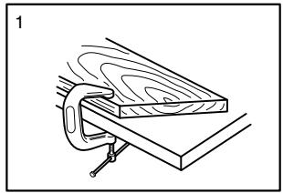
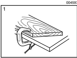
For Frame Joint and Edge-To-Edge Joint only
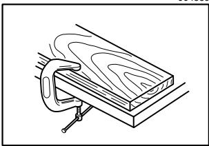
Clamp one workpiece to the workbench.
004591
1. For Frame Joint
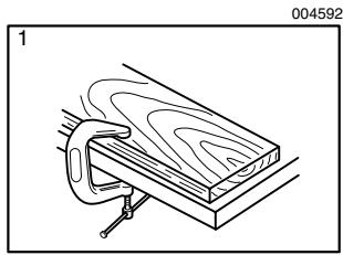
1. For Edge-To-Edge Joint
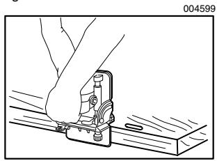
- Set the depth of cut according to the size of biscuit to be used. Refer to the table in the "Adjusting the depth of cut" section.
- Adjust the angle guide height so that the blade is centered in the board thickness.
- Align the center mark on the base with the pencil line on the workpiece.
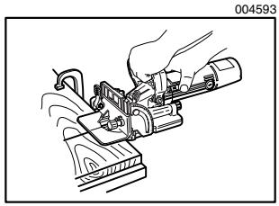
- Switch on the tool and gently push it forward to extend the blade into the workpiece.
- Gently return the tool to the original position after the adjusting screw reaches the stopper.
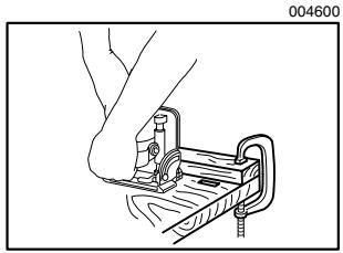
9. For Corner Joint and T-Butt Joint only
Clamp the horizontal workpiece to the workbench.
004594
1. For Corner Joint
1. For T-Butt Joint
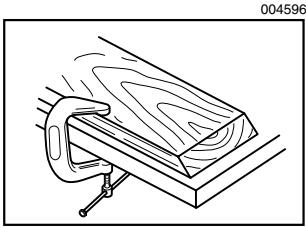
For Miter Joint only
Clamp the other workpiece to the workbench with the mitered edge facing up.
For Frame Joint and Edge-To-Edge Joint only
Clamp the other workpiece to the workbench.
1. For Frame Joint
1. For Edge-To-Edge Joint
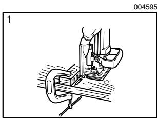
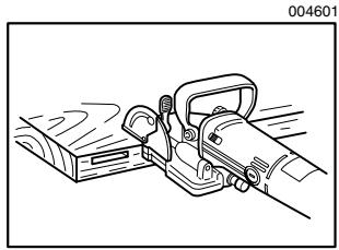
10. For Corner Joint only
Place the tool on the workpiece so that the blade is facing down.
For T-Butt Joint only
Remove the angle guide from the tool. Place the tool on the workpiece so that the blade is facing down.
- Repeat the steps 6 - 8 to cut the slots in the horizontal or the other workpiece.
If you do not need to center the blade in the board thickness, proceed as follows:
For Corner Joint, Miter Joint, Frame Joint and Edge-To-Edge Joint only
- Remove the angle guide from the tool. Set the fence at 90^ for Corner Joint, Frame Joint and Edge-To-Edge Joint or at 45^ for Miter Joint.
- Follow steps 1 - 11 excluding steps 5 and 10 described above.
For T-Butt Joint only
- Fit the two workpieces together as they will appear in the finished joint position.
- Lay the vertical workpiece on the horizontal one. Clamp both workpieces to the workbench.
- Remove the angle guide from the tool.
- Follow the steps 2, 4, 6, 7, 8 and 11 described above.
How to trim wall or ceiling panels
First unplug the tool. Open the blade cover and replace the existing cutter blade with an optional circular saw blade 110mm (4 - 3 / 8^ ) in diameter.
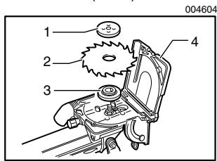
- Lock nut
- Circular saw blade
- Inner flange
- Blade cover
Refer to the "Removing or installing the blade" section which was described previously. Remove the rubber facing from the base. Then close and secure the blade cover. Now the max. depth of cut is 25mm (1").
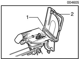
1. Rubber facing
2. Blade cover
CAUTION:
- Be very careful that the blade has been properly mounted on the tool spindle between the inner flange and the lock nut. Be sure to securely tighten the lock nut.
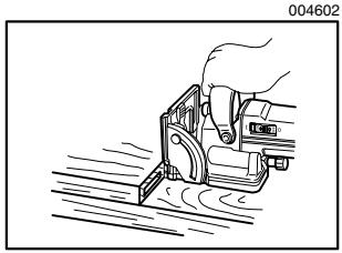
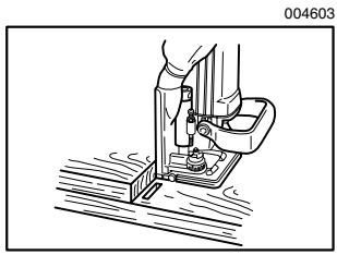
Set the depth of cut to "MAX". Rest the base on the floor (when trimming the wall panels) or the wall (when trimming the ceiling panels). Using the floor or wall as a guide, trim wall or ceiling panels. Feed in the direction of the arrow.
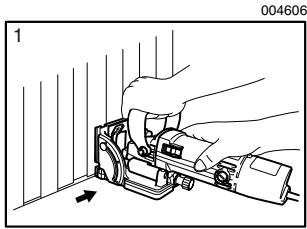
1. When trimming the wall panels
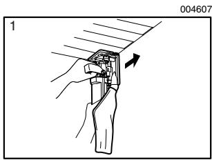
1. When trimming the ceiling panels
CAUTION:
Before trimming the panels, check the wall or ceiling carefully to avoid cutting the electrical wires, nails or other foreign materials.
Always reinstall the rubber facing after trimming the panels. If cutting slots for biscuits without the rubber facing installed properly on the tool, the tool might slip unexpectedly on the workpiece, causing dangerous loss of control of the tool. When installing the rubber facing, always hook it onto the inside of the front opening.
MAINTENANCE
CAUTION:
Always be sure that the tool is switched off and unplugged before attempting to perform inspection or maintenance.
Replacing carbon brushes
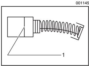
1. Limit mark
Remove and check the carbon brushes regularly. Replace when they wear down to the limit mark. Keep the carbon brushes clean and free to slip in the holders. Both carbon brushes should be replaced at the same time. Use only identical carbon brushes.
Use a screwdriver to remove the brush holder caps. Take out the worn carbon brushes, insert the new ones and secure the brush holder caps.
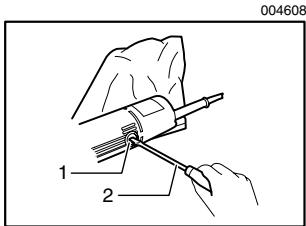
1. Brush holder cap
2. Screwdriver
To maintain product SAFETY and RELIABILITY, repairs, any other maintenance or adjustment should be performed by Makita Authorized or Factory Service Centers, always using Makita replacement parts.
ACCESSORIES
CAUTION:
These accessories or attachments are recommended for use with your Makita tool specified in this manual. The use of any other accessories or attachments might present a risk of injury to persons. Only use accessory or attachment for its stated purpose.
If you need any assistance for more details regarding these accessories, ask your local Makita Service Center.
Angle guide
Dust bag
Set plate 4
- Lock nut wrench 20
- Cutter blade 100-4
Cross-cut saw blade
Combination saw blade - Carbide-tipped saw blade
EN0006-1
MAKITA LIMITED ONE YEAR WARRANTY
Warranty Policy
Every Makita tool is thoroughly inspected and tested before leaving the factory. It is warranted to be free of defects from workmanship and materials for the period of ONE YEAR from the date of original purchase. Should any trouble develop during this one year period, return the COMPLETE tool, freight prepaid, to one of Makita's Factory or Authorized Service Centers. If inspection shows the trouble is caused by defective workmanship or material, Makita will repair (or at our option, replace) without charge.
This Warranty does not apply where:
- repairs have been made or attempted by others:
- repairs are required because of normal wear and tear:
the tool has been abused, misused or improperly maintained:
alterations have been made to the tool.
IN NO EVENT SHALL MAKITA BE LIABLE FOR ANY INDIRECT, INCIDENTAL OR CONSEQUENTIAL DAMAGES FROM THE SALE OR USE OF THE PRODUCT. THIS DISCLAIMER APPLIES BOTH DURING AND AFTER THE TERM OF THIS WARRANTY.
MAKITA DISCLAIMS LIABILITY FOR ANY IMPLIED WARRANTY, INCLUDING IMPLIED WARRANTY OF "MERCHANTABILITY" AND "FITNESS FOR A SPECIFIC PURPOSE," AFTER THE ONE YEAR TERM OF THIS WARRANTY.
This Warranty gives you specific legal rights, and you may also have other rights which vary from state to state. Some states do not allow the exclusion or limitation of incidental or consequential damages, so the above limitation or exclusion may not apply to you. Some states do not allow limitation on how long an implied warranty lasts, so the above limitation may not apply to you.
FRANÇAIS
SPÉCIFICATIONS
Some dust created by power sanding, sawing, grinding, drilling, and other construction activities contains chemicals known to the State of California to cause cancer, birth defects or other reproductive harm. Some examples of these chemicals are:
- lead from lead-based paints,
crystalline silica from bricks and cement and other masonry products, and - arsenic and chromium from chemically-treated lumber.
Your risk from these exposures varies, depending on how often you do this type of work. To reduce your exposure to these chemicals: work in a well ventilated area, and work with approved safety equipment, such as those dust masks that are specially designed to filter out microscopic particles.
< USA solamente >
ADVERTENCIA

- GENERAL SAFETY RULES
- WARNING:
- SAVE THESE INSTRUCTIONS
- Work area safety
- Electrical safety
- Personal safety
- Power tool use and care
- Service
- Specific Safety Rules
- SAVE THESE INSTRUCTIONS.
- SYMBOLS
- FUNCTIONAL DESCRIPTION
- CAUTION:
- Angle guide
- Fence
- Set plate
- Switch action
- ASSEMBLY
- Removing or installing the blade
- Dust bag
- NOTE:
- OPERATION
- How to make joints
- For Corner Joint and T-Butt Joint only
- For Miter Joint only
- For Frame Joint and Edge-To-Edge Joint only
- For Corner Joint and T-Butt Joint only
- For Corner Joint only
- For T-Butt Joint only
- How to trim wall or ceiling panels
- MAINTENANCE
- ACCESSORIES
- MAKITA LIMITED ONE YEAR WARRANTY
- Warranty Policy
- ADVERTENCIA
Brand : MAKITA
Model : 3901
Category : Power Tools