
DBC260L - Brush cutter MAKITA - Free user manual and instructions
Find the device manual for free DBC260L MAKITA in PDF.

| Product Type | Brushcutter |
| Brand | Makita |
| Model | DBC260L |
| Handle Type | Loop handle (delta) |
| Dimensions (L x W x H) | 1 770 x 315 x 235 mm |
| Weight (without blade or guard) | 4,8 kg |
| Fuel Type | 2-stroke gasoline/oil mixture 50:1 |
| Tank Capacity | 0,6 L |
| Engine Displacement | 25,7 cm³ |
| Max Power | 0,83 kW at 8 000 min⁻¹ |
| Max Engine Speed | 10 000 min⁻¹ |
| Max Shaft Speed | 7 400 min⁻¹ |
| Idle Speed | 3 000 min⁻¹ |
| Spark Plug | NGK BPMR7A |
| Electrode Gap | 0,6 - 0,7 mm |
| Sound Level (Acoustic Pressure) | 98,2 dB |
| Sound Level (Acoustic Power) | 108,5 dB |
| Vibration Right Handle | 5,3 m/s² |
| Vibration Left Handle | 4,3 m/s² |
| Cutting Device | Nylon line head (automatic and manual feed) |
Frequently Asked Questions - DBC260L MAKITA
User questions about DBC260L MAKITA
0 question about this device. Answer the ones you know or ask your own.
Ask a new question about this device
Download the instructions for your Brush cutter in PDF format for free! Find your manual DBC260L - MAKITA and take your electronic device back in hand. On this page are published all the documents necessary for the use of your device. DBC260L by MAKITA.
USER MANUAL DBC260L MAKITA
Read this instruction manual carefully before putting the Brush Cutter/String Trimmer and strictly observe the safety regulations! Store this instruction manual in a safe place for future reference.
Important:
Thank you for purchasing this MAKITA Brush Cutter/String Trimmer. MAKITA Brush Cutters/String Trimmers are developed as a product of our many years of knowledge, experience, and a detailed development programme. Please read this booklet thoroughly to ensure you gain the best possible performance and outstanding results that your MAKITA Brush Cutter/String Trimmer can provide.

Table of Contents
Symbols 3
Safety instructions 4
Technical data DBC260U, DBC260L 8
Names of parts. 9
Mounting the handle 10
Mounting the protector 11
Mounting the cutter blade/nylon cutting head 12
Fuel/Refuelling 13
Correct handling. 14
Important operating points/stopping
the cutter/trimmer 14
Resharpening the cutting tool 16
Servicing instructions 17
Storage 19
Symbols
You need to note the following symbols when reading the instructions manual.
| Read instruction Manual | Wear eye and ear protection (for String Trimmer only) |
Safety instructions
General Instructions
- To ensure correct operation, make sure that you read and fully understand this instruction manual to familiarise yourself with how to use the Brush Cutter/ String Trimmer. Using this equipment without understanding how to operate it correctly may result in serious injury to yourself or others.
- Only lend the Brush Cutter/String Trimmer to people who have proved experienced with Brush Cutter/String Trimmers. Always lend them this instruction manual at the same time.
- If this is your first time using an engine powered cutter, consult your dealer for basic instructions.
- Children and young persons aged under 18 years must not be allowed to operate the Brush Cutter/String Trimmer. Persons over the age of 16 years may use the device for training purposes, only whilst under supervision of a qualified trainer.
- Use Brush Cutter/String Trimmers with the utmost care and attention.
- Only operate the Brush Cutter/String Trimmer if you are in good physical condition. Perform all work calmly and carefully. Users must accept responsibility for those around them.
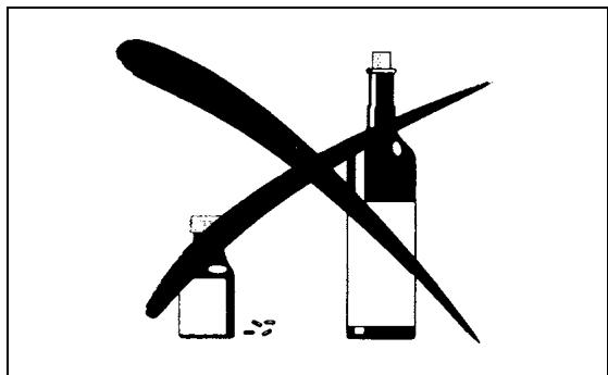
- Never use the Brush Cutter/String Trimmer after consumption of alcohol or medicines, or if you are feeling tired or ill.
Intended use of the equipment
- The Brush Cutter/String Trimmer is only intended for cutting grass, weeds, bush and other such undergrowth, and should not be used for any other purpose such as edging or hedge cutting as this may cause injury.
Personal protective equipment
- Always wear clothing that is both functional and appropriate to your work, i.e. tight-fitting, but not so tight as to cause uncomfortable movement. Do not wear either jewelry or clothing which could become entangled with bushes or shrubs.
- In order to avoid head, eye, hand, or foot injuries, as well as to protect your hearing during operation, the following protective equipment and protective clothing must be used while using the Brush Cutter/String Trimmer.
- Always wear a helmet where there is a risk of falling objects. The protective helmet (1) is to be checked at regular intervals for damage and is to be replaced at the latest after 5 years. Use only approved protective helmets.
- The visor (2) of the helmet (or alternatively goggles) protects the face from flying debris and stones. During operation of the Brush Cutter/String Trimmer, always wear goggles or a visor to prevent eye injuries.
- Wear adequate noise protection equipment to avoid hearing impairment (ear muffs (3), ear plugs etc.).
- Work overalls (4) protect against flying stones and debris. We strongly recommend that you wear work overalls.
- Special gloves (5) made of thick leather are part of the prescribed equipment and must always be worn during operation of the Brush Cutter/String Trimmer.
- When using the Brush Cutter/String Trimmer, always wear sturdy shoes (6) with a non-slip sole. Such shoes protect against injuries and ensure good footing.
Starting the brush cutter
- Make sure that there are no children or other people within a working range of 15 meters (50ft), also pay attention to any animals in the working vicinity.
- Before use, always check that the Brush Cutter/String trimmer is safe for operation: Check that the cutting tool is secure, that the control lever can be operated easily, and that the control lever lock is functioning correctly.
- Rotation of the cutting tool during idling is prohibited. Check with your dealer if you think the equipment may need adjusting. Check to make sure that the handles are clean and dry, and that the start/stop switch is functioning correctly.


- Start the Brush Cutter/String Trimmer only in accordance with the instructions. Do not use any other methods to start the engine!
- Only use the Brush Cutter/String Trimmer and tools for the specified purposes.
- Only start the Brush Cutter/String Trimmer engine after the equipment is fully assembled. Do not operate the equipment until all of the appropriate accessories are attached!
- Before starting, make sure that the cutting tool is not in contact with hard objects such as branches, stones etc. as the cutting tool will rotate when starting.
- Switch off the engine immediately if any type of engine problem occurs.
- Should the cutting tool hit stones or other hard objects, immediately switch off the engine and inspect the cutting tool.
- Inspect the cutting tool at short regular intervals for damage (inspect for hairline cracks using the tapping test).
- Only operate the Brush Cutter/String Trimmer after attaching and adjusting the shoulder strap to the correct length. The shoulder strap must be adjusted to the user's size and fastened to prevent fatigue during operation of the equipment. Never hold the cutter with one hand during operation.
- During operation, always hold the Brush Cutter/String Trimmer with both hands. Always ensure you are on safe footing.
- Operate the Brush Cutter/String Trimmer in such a manner as to avoid inhalation of the exhaust gases. Never run the engine in an enclosed space such as inside a room (risk of gas poisoning). Carbon monoxide is an odorless gas.
- Always switch off the engine when resting, or if you intend to leave the Brush Cutter/String Trimmer unattended, and place it in a safe location to prevent injury to other people and damage to the equipment.
- Never put the hot Brush Cutter/String Trimmer onto dry grass or onto any other combustible materials.
- The cutting tool must always be equipped with the appropriate guard. Never run the cutter without this guard!
- All protective installations and guards supplied with the equipment must be used during operation.
- Never operate the engine if the exhaust muffler is faulty.
- Shut off the engine during transport.
- During transport over long distances, always use the tool protection equipment included.
- Ensure the Brush Cutter/String Trimmer is positioned safely during transport to avoid fuel leakage.
- When transporting the Brush Cutter/String Trimmer, ensure the fuel tank is completely empty.
- When unloading the Brush Cutter/String Trimmer from a truck or other such vehicle, never drop the engine to the ground, as doing so may severely damage the fuel tank.
Unless in an emergency, never drop or cast the Brush Cutter/String Trimmer to the ground as doing so may severely damage the Brush Cutter/String Trimmer. - Always lift the entire equipment from the ground when moving it. Dragging the equipment on its fuel tank is extremely dangerous and may cause fuel to leak, which may cause fire.
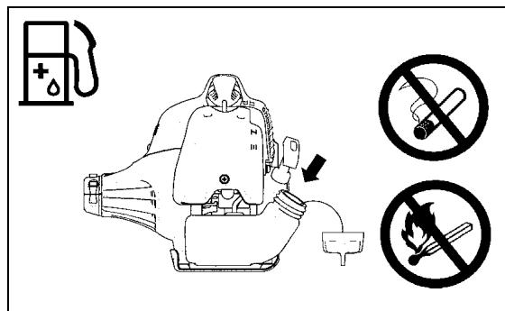
Refuelling
- Shut off the engine during refuelling, keep away from open flames and do not smoke during refuelling.
- Ensure mineral oil products do not come into contact with skin. Do not inhale the fuel vapor. Always wear protective gloves during refuelling. Change and clean protective clothing at regular intervals.
- To prevent soil contamination (environmental protection), make sure you do not spill fuel or oil on the ground. If you do spill fuel, clean the Brush Cutter/ String Trimmer immediately.
- Make sure fuel does not come into contact with your clothing. If fuel does come into contact with your clothing, change your clothing immediately to prevent fire.
- Inspect the fuel cap at regular intervals to make sure that it can be securely fastened and does not leak.
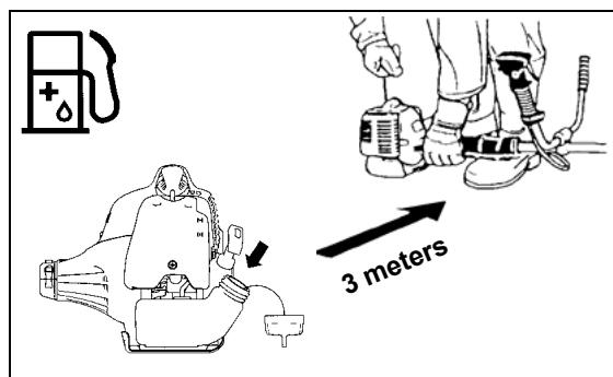
- Carefully tighten the fuel tank cap. Once refuelling is complete, move to a location at least 3 meters away from where you refuelled before starting the engine.
- Never refuel in an enclosed space such as inside a room. Doing so may cause an explosion due to the accumulation of fuel vapor at ground level.
- Only transport and store fuel in approved containers. Make sure stored fuel is not accessible to children.

Method of operation
- Only use the Brush Cutter/String Trimmer in good light and visibility. During the winter season, beware of slippery or wet areas such as icy or snow-covered areas (risk of slipping). Always ensure you are on safe footing.
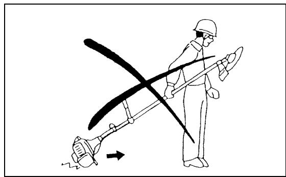
- Never cut above waist height.
- Never stand on a ladder while using the Brush Cutter/String Trimmer.
- Never climb up into trees to use with the Brush Cutter/String Trimmer.
- Never work on unstable surfaces.
- Remove sand, stones, nails etc. found within the working range.
Foreign objects may damage the cutting tool and can cause dangerous kickbacks.
- Before starting to cut, make sure the cutting tool has reached full working speed.
Kickback
- When operating the brush cutter, uncontrolled kickbacks may occur.
- Kickbacks occur frequently when attempting to cut with the 12 to 2 o'clock section of the blade.
- Never apply the 12 to 2 o'clock section of the brush cutter blade.
- Never apply this section of the brush cutter blade to solid objects, such as bushes or trees etc. that have a diameter greater than 3cm . Doing so will cause the brush cutter to deflect with a large amount of force, which is extremely dangerous and may cause injury.
Kickback prevention
To avoid kickbacks, remember the following:
- Using the 12 to 2 o'clock section of the blade is extremely hazardous, especially when using metal cutting tools.
- Cutting operations using the 11 to 12 o'clock section and 2 to 5 o'clock section of the blade must only be performed by trained and experienced operators, and then only at their own risk.
The optimum cutting section for easy cutting with almost no kickback is between the 8 to 11 o'clock section of the blade.
Cutting Tools
Ensure you use the correct cutting tool for each particular job.
DBC260U with cutter blade (Star Blade (4 teeth), Eddy Blade (8 teeth)), DBC260L with Nylon cutting head.
For cutting thick materials such as weed, high grass, bushes, shrubs, underwood, thicket etc. (max. 2 cm dia. thickness). Perform this cutting work by swinging the brush cutter evenly in half-circles from right to left (in a similar way to using a scythe).
Maintenance instructions
- Always check the condition of the cutter, in particular the cutter protective devices and shoulder strap, before commencing work. Particular attention should also be paid to the cutting blades, which must be correctly sharpened.
- Turn off the engine and remove the spark plug connector when replacing or sharpening cutting tools, and also when cleaning the cutter or cutting tool.


Never straighten or weld damaged cutting tools.
- Operate the Brush Cutter/String Trimmer with as little noise and contamination as possible. In particular, check that the carburetor is set correctly.
- Clean the Brush Cutter/String Trimmer at regular intervals and check that all screws and nuts are well tightened.
- Never service or store the Brush Cutter/String Trimmer in the vicinity of naked flames.
- Always store the Brush Cutter/String Trimmer in locked rooms and with an emptied fuel tank.
Observe the relevant accident prevention instructions issued by the relevant trade associations and insurance companies.
Do not perform any modifications on the Brush Cutter/String Trimmer, as doing so will endanger your safety.
The performance of maintenance or repair work by the user is limited to those activities described in the instruction manual. All other work is to be done by an Authorized Service Agent. Use only genuine spare parts and accessories released and supplied by MAKITA.
Using non-approved accessories and tools will cause an increased risk of accidents.
MAKITA will not accept any liability for accidents or damage caused by the use of non-approved cutting tools, fixing devices of cutting tools, or accessories.
First Aid
In case of accident, make sure that a first-aid box is available in the vicinity of the cutting operations. Immediately replace any item taken from the first aid box.
When asking for help, please give the following information:
- Place of the accident
- What happened
Number of injured persons - Kind of injuries
- Your name


Packaging
The MAKITA Brush Cutter/String Trimmer is delivered in two protective cardboard boxes to prevent transport damage. Cardboard is a basic raw material and is therefore reusable or suitable for recycling (waste paper recycling).


EC-DECLARATION OF CONFORMITY
Model; DBC260U, DBC260L
We declare under our sole responsibility that this product is in compliance with the following standards of standardized documents, ISO11806, EN55012 in accordance with Council Directives, 89/392/EEC, amended 98/37/EEC, 93/68/EEC, 89/336/EEC, amended 92/31/EEC.
Measured Sound Power: 111.7 dB
Guarantee Sound Power: 114 dB
These sound power levels were measured in accordance with Council Directive, 2000/14/EC.
Conformity assessment procedure: Annex V.

CE2008
Tomoyasu Kato
Director
Responsible Manufacturer:
Makita Corporation.
3-11-8,Sumiyoshi-cho,Anjo,Aichi,JAPAN
Authorized Representative in Europe:
Makita International Europe Ltd.
Michigan Drive, Tongwell, Milton kyenes, Bucks MK15 8JD, ENGLAND
Technical data DBC260U, DBC260L
| Model | DBC260U | DBC260L | |
| U handle | Loop handle | ||
| Dimensions: length x width x height (without cutting blade) mm | 1,770 x 630 x 410 | 1,770 x 315 x 235 | |
| Mass (without plastic guard and cutting blade) kg | 5.0 | 4.8 | |
| Volume (fuel tank) L | 0.6 | ||
| Engine displacement cm3 | 25.7 | ||
| Maximum engine performance kw | 0.83 at 8,000 min-1 | ||
| Engine speed at recommended max. spindle speed min-1 | 10,000 | ||
| Maximum spindle speed (corresponding) min-1 | 7,400 | ||
| Maximum fuel consumption kg/h | 0.431 | ||
| Maximum specific fuel consumption g/kwh | 487 | ||
| Idling speed min-1 | 3,000 | ||
| Clutch engagement speed min-1 | 4,000 | ||
| Carburetor type | WALBRO WYC | ||
| Ignition system type | Solid state ignition | ||
| Spark plug type | NGK BPMR7A | ||
| Electrode gap mm | 0.6 - 0.7 | ||
| Vibration per ISO 228671) | Right handle (Rear grip) m/s2 | 3.8 | 5.3 |
| Left handle (Front grip) m/s2 | 3.9 | 4.3 | |
| Sound pressure level average to ISO 228681) db | 98.2 | ||
| Sound power level average to ISO 228681) db | 108.5 | ||
| Fuel | Mixed gas (gasoline: Makita Genuine Two-stroke Engine Oil =50:1) | ||
| Gear ratio | 14/19 | ||
1) The data takes equally into account the idling and racing or wide open throttle speed operating modes.

DBC260U
U Handle Type
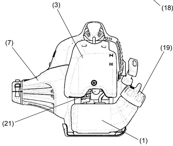
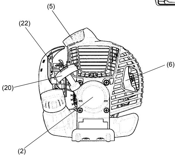
| Names of parts | |
| 1 | Fuel Tank |
| 2 | Rewind Starter |
| 3 | Air Cleaner |
| 4 | I-O Switch (on/off) |
| 5 | Spark Plug |
| 6 | Exhaust Muffler |
| 7 | Clutch Case |
| 8 | Rear Grip |
| 9 | Hanger |
| 10 | Handle |
| 11 | Control Lever |
| 12 | Control Cable |
| 13 | Shaft |
| 14 | Protector |
| 15 | Gear Case |
| 16 | Handle Holder |
| 17 | Cutter Blade |
| 18 | Nylon Cutting Head |
| 19 | Fuel Filler Cap |
| 20 | Starter Knob |
| 21 | Primer Pump |
| 22 | Choke Lever |
Mounting the handle
CAUTION: Before doing any work on the brush cutter, always stop the engine and disconnect the spark plug connector from the spark plug. Always wear protective gloves!
CAUTION: Ensure you have reassembled the brush cutter completely before starting it.
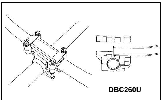
For U Handle models
- Place the handle-fixing metal so that the handle with the control lever is positioned on the right (the right-hand grip side) when viewed from the engine side.
- Fit the groove of the handle-fixing material to the handle end. Temporarily fix the attached metal using the hexagon socket bolt provided.
-
Adjust the handle to an easy-to-operate position, and securely tighten the four hexagon socket bolts uniformly on the right and left using an Allen key.
-
Fit the control cable (together with the earth cord) to the handle with two clips (1).
- Make sure the control cable does not loop at the handle bar section.


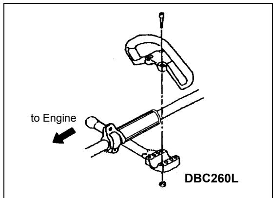
For Loop Handle models
- Fix the barrier to the left side of the equipment together with the handle to protect the operator.
- Do not adjust position of the loop handle too close to the control grip.
- Keep a distance of at least 250mm between the handle and the grip. (a distance collar is provided for this purpose.)
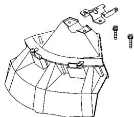
Mounting the protector
To meet the applicable safety standards, you must only use the tool/protector combinations indicated in the table.
Always use genuine MAKITA cutter blades/nylon cutting head.
- The cutter blade must be well polished, and free of cracks or breakages. If the cutter blade hits against a stone during operation, stop the engine and check the blade immediately.
- Polish or replace the cutter blade every three hours of operation.
- If the nylon cutting head hits against a stone during operation, stop the engine and check the nylon cutting head immediately.


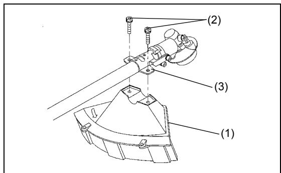
CAUTION: The appropriate protectors must always be installed for your own safety and in order to comply with accident-prevention regulations. Operation of the equipment without the guard installed is prohibited.
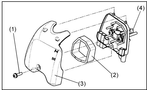
Fix the protector (1) to the clamp (3) with two M6 x 30 bolts (2).
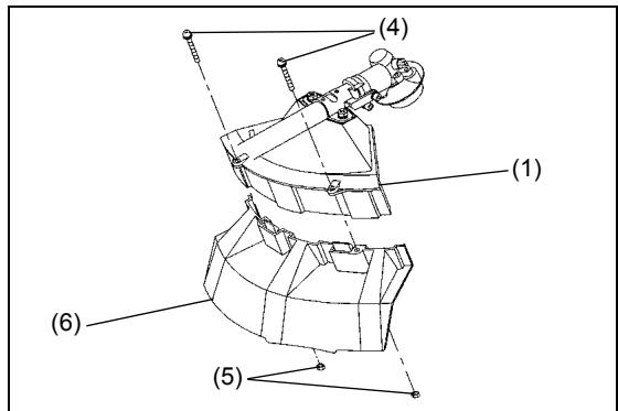
- When using the string head, fit the protector (6) into the protector (1), and tighten them with two nuts (5) and two screws (4).

Nylon cutting head
PART NO. 6218016000
Protector for cord cutter
PART NO. 6258064000
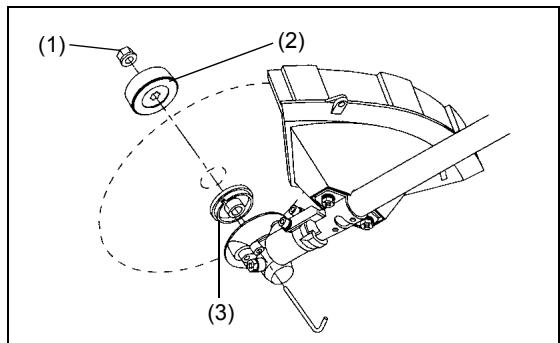
Mounting the cutter blade/nylon cutting head
The cutter blade or nylon cutting head can be replaced easily by first turning the equipment upside down.
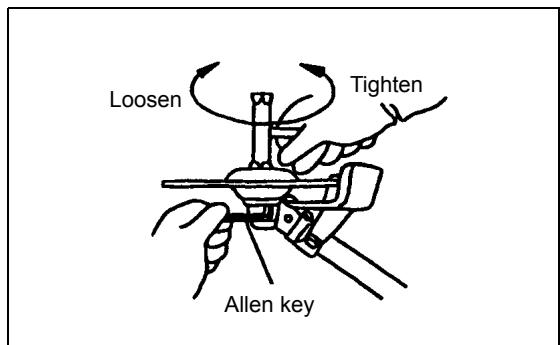
- Insert the Allen key through the hole in the gear case and rotate the receiver washer (3) until it is locked with the Allen key.
- Loosen the nut (1) (left-hand thread) with the socket wrench, and remove the nut (1) and clamp washer (2).
With the Allen key still in place
- Mount the cutter blade onto the shaft so that the guide of the receiver washer (3) fits in the arbor hole in the cutter blade. Install the clamp washer (2) and secure the cutter blade with the nut (1).
[Tightening torque: 13 - 23 N-m]
NOTE: Always wear gloves when handling the cutter blade.
NOTE: The cutter blade-fastening nut (with spring washer) is a consumable part. If there appears any wear or deformation on the spring washer, replace the nut.
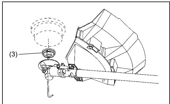
NOTE: The clamp washer (2), and nut (1) are not necessary for mounting the nylon cutting head. The nylon head should go on top of the receiver washer (3).
- Screw the nylon cutting head onto the shaft.
- Make sure that the blade rotates counterclockwise.


Handling fuel
Ultmost care is required when handling fuel. Fuel may contain substances similar to solvents. Refuel either in a well ventilated room or outdoors. Do not inhale fuel vapors, and avoid any contact of fuel or oil with your skin.
Mineral oil products degrease your skin. Prolonged skin contact with these products will cause your skin to become extremely dry, which may result in various kinds of skin disease. In addition, allergic reactions may occur.
Eyes can be irritated by contact with oil. If oil comes into your eyes, immediately wash them with clear water. If your eyes are still irritated, see a doctor immediately.
Fuel and oil mixture
The brush cutter engine is a high-efficiency two-stroke engine. It runs on a mixture of fuel and two-stroke engine oil. The engine is designed for unleaded regular fuel with a min. octane value of 91 RON. If for any reason no such fuel is available, you can use fuel with a higher octane value. This will not affect the engine, but it may cause poor operating behaviour.
Similar problems will arise from the use of leaded fuel. To obtain optimum engine operation and to protect your health and the environment, use only unleaded fuel!
To lubricate the engine, add two-stroke engine oil (quality grade: JASO FC or ISO EGD) to the fuel. The engine has been designed to use the specified two-stroke engine oil at a mixture ratio of 50:1 to protect the environment.
Additionally, long service life accompanied by reliable operation and minimum emissions are guaranteed through the use of this mixture ratio. Reliable functioning of the brush cutter cannot be guaranteed unless this mixture ratio of 50:1 (specified 2-stroke engine oil) is strictly observed.
Correct mixture ratio:
Gasoline: Specified two-stroke engine oil = 50 : 1 or
Gasoline: Other manufacturer's two-stroke engine oil = 25 : 1 recommended
NOTE: To prepare the fuel-oil mixture, first mix the entire oil quantity with half of the fuel required, then add the remaining fuel. Thoroughly shake the mixture before pouring it into the brush cutter tank. To ensure safe operation, do not add more engine oil than the specified amount. Doing so will only result in a higher production of combustion residues which pollute the environment and clog the exhaust channel in the cylinder as well as the muffler. In addition, the fuel consumption will rise and the performance will decrease.
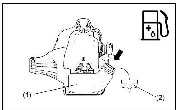
Refuelling
The engine must be switched off.
- Thoroughly clean the area around the fuel filler cap (2) to prevent dirt from getting into the fuel tank (1).
- Unscrew the fuel filler cap (2) and fill the tank with fuel.
- Tightly screw on the fuel filler cap (2).
- Clean the screw fuel filler cap (2) and tank after refueling.
Storage of Fuel
Fuel cannot be stored for an unlimited period of time.
Purchase only the quantity required for a 4-week operating period. Only use approved fuel storage containers.


Observe the Safety Instructions on page 4.

| Gasoline | 50:1 | 25:1 |
| 1,000 cm3(1 liter) | 20 cm3 | 40 cm3 |
| 5,000 cm3(5 liter) | 100 cm3 | 200 cm3 |
| 10,000 cm3(10 liter) | 200 cm3 | 400 cm3 |
Correct handling
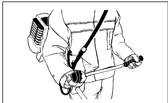
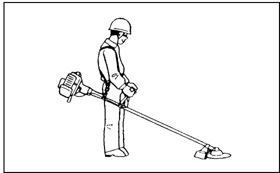
Attachment of shoulder strap
- Adjust the strap length so that the cutter blade is kept parallel with the ground.
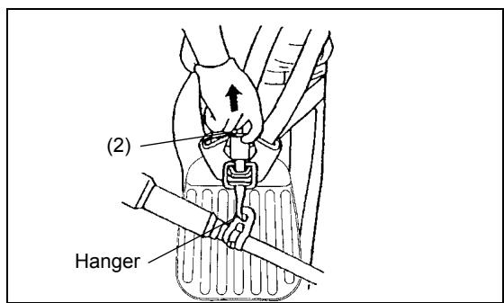
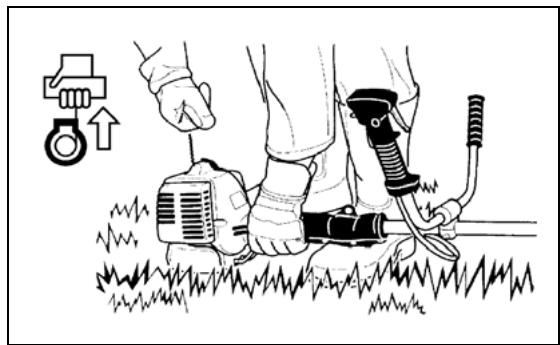
Detachment
For DBC260U
- In case of emergency, to detach the equipment from your body, strongly pull the emergency detachment lever (2) with your finger. This will detach the equipment sill from the body.
Be extremely careful to maintain control of the equipment at this time. Do not allow the equipment to be deflected toward you or anyone in your vicinity.
WARNING: Failure to maintain complete control of the equipment could result in serious injury or DEATH.
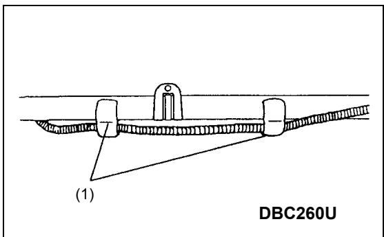
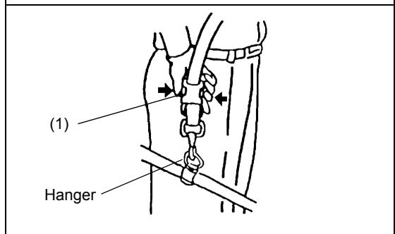
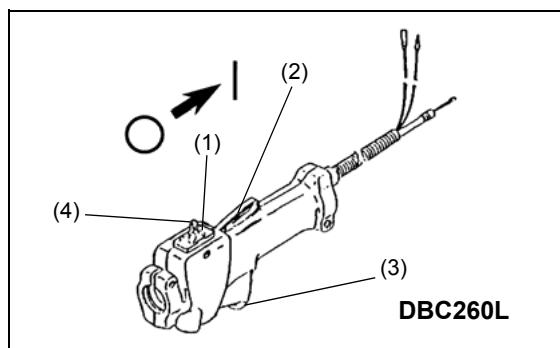
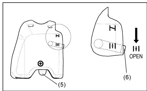
For DBC260L
- In case of emergency, push the notches (1) at both sides, and detach the equipment.
Be extremely careful to maintain control of the equipment at this time. Do not allow the equipment to be deflected toward you or anyone in your vicinity.
WARNING: Failure to maintain complete control of the machine at all could result in serious injury or DEATH.
Important operating points/stopping the cutter/trimmer
Observe the applicable accident prevention regulations.

Starting
Move at least 3 m away from the area where you refuelled the equipment. Place the brush cutter on a clean piece of ground taking care that the
cutting tool does not come into contact with the ground or any other objects.
Cold start
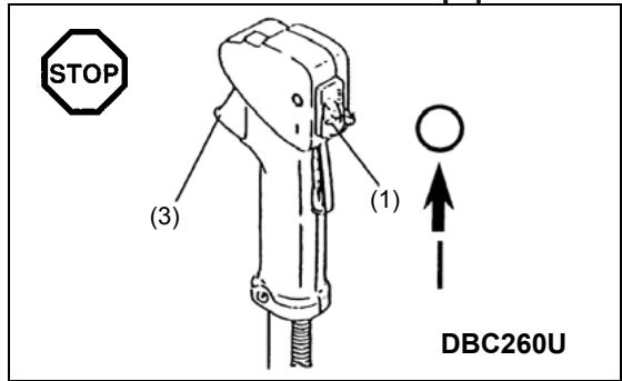
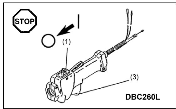
- Push the I-O switch (1) in the direction shown by the arrow.
- Grasp the handle (hand pressure activates the safety lock-off lever (2)).
- Press the throttle lever (3) and hold it down.
- Press the lock button (4) and release the control lever, and then release the lock button (the lock button holds the throttle lever in the start-up position).
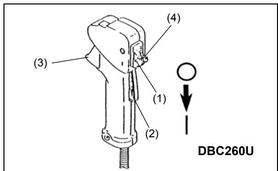
- First, place the equipment on the ground.
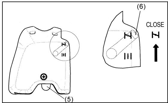
- Gently press the primer pump (5) repeatedly (7-10 times) until fuel comes into the primer pump.
- Close the choke lever (6).
Choke opening:
- Fully closed in cold temperatures or when the engine is cold
-
Fully or half open for restart while the engine is still warm
-
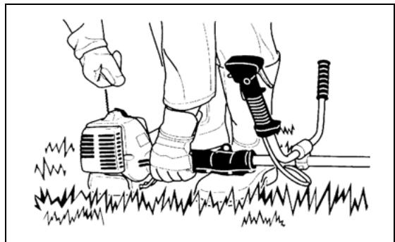
Firmly hold the clutch case with your left hand, as illustrated.
- Slowly pull the starter grip until you feel resistance, and then continue to pull sharply.
- Do not pull out the starter rope to its full extent, and do not allow the starter handle to retract by itself. Maintain control of the starter rope and ensure it retracts slowly.
- Repeat the starting operation until you hear the engine's initial ignitions.
- Depress the choke lever (6) (11) and pull the starter rope again until the engine starts.
- As soon as the engine starts, immediately tap and release the throttle, to release the half-throttle lock and allow the engine to idle.
- Run the engine for approximately one minute at a moderate speed before applying full throttle.
NOTE: - If you pull the starter handle repeatedly when the choke lever is in the at "▶" position, the engine will not start easily due to excessive fuel intake.
- If excessive fuel intake occurs, remove the spark plug and pull the starter handle slowly to remove excess fuel. Also, dry the electrode section of the spark plug.
Caution during operation:
If the throttle lever is opened fully during a no-load operation, the engine revolutions increase over 10,000min^-1 . Never operate the engine at a higher speed than required, and keep the revolutions at an approximate speed of 6,000 - 8,000 min^-1 .
CAUTION: Always reduce the engine revolutions when the equipment is not being used for work.
Operating the equipment at high revolutions when not being used for work will shorten the lifespan of the equipment.
Warm start
- Follow the instructions for cold start above, except without moving the choke lever (choke lever remains in the down position ( ) ).
Stopping
- Release the throttle lever (3) fully, and when the engine rpm has lowered, push the I-O switch (1) to "O" position to stop the engine.
- Be aware that the cutting head may not stop immediately, and always allow it to slow down and stop fully by itself.
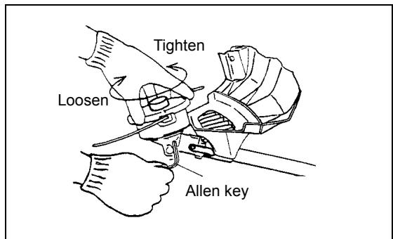
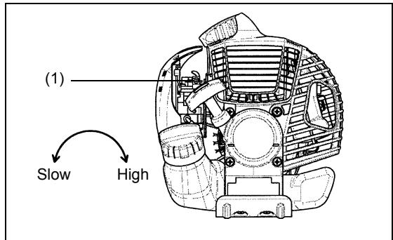
ADJUSTMENT OF LOW-SPEED REVOLUTIONS (IDLING)
The cutter blade or the nylon cutting head should not rotate when the control lever is fully released. If necessary, adjust the idling rpm using the idling adjustment screw.
Checking the Idling speed
- The idling speed should be set to 3,000min^-1 . If necessary, adjust the idling speed using the idling screw (the blade or the nylon cutting head must not turn when the engine is idling). Tightening the idling screw (1) increases the engine revolutions, whereas loosening the idling screw reduces the engine revolutions.
Resharpening the cutting tool
CAUTION: The cutting tools listed below must only be resharpened by an authorized facility. Manual resharpening will result in imbalances of the cutting tool, which will cause vibrations and damage to the equipment.
- cutter blade (star blade (4 teeth), eddy blade (8 teeth))
A professional resharpening and balancing service is provided by Authorized Service Agents.
NOTE: To increase the service life of the cutter blade (star blade, eddy blade) the blade may be turned over to allow both cutting edges to wear.
NYLON CUTTING HEAD
The nylon cutting head is a dual string trimmer head capable of both automatic and bump & feed mechanisms. The nylon cutting head will automatically feed out the proper length of nylon cord by the changes in centrifugal force caused by increasing or decreasing rpms. However, to cut soft grass more efficiently, bump the nylon cutting head against the ground to feed out extra cord as shown in operation section.
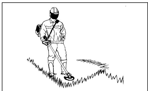
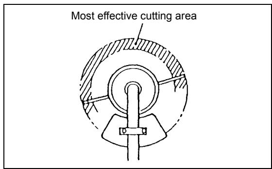
Operation
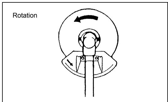
- Increase the nylon cutting head speed to approx. 6,000 ~min^-1 . Nylon cord will not feed out correctly at lower speeds (under 4,800 ~min^-1 ).
- The most effective cutting area is shown by the shaded area in the diagram to the right.
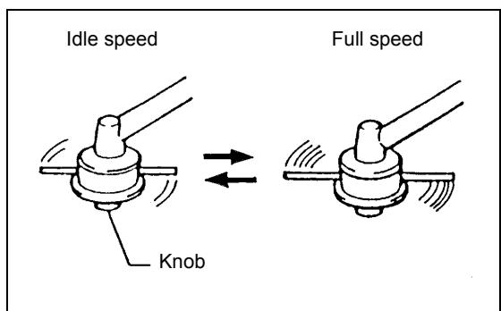
If the nylon cord does not feed out automatically, follow the instructions below:
- Release the throttle lever so that the engine idles, and then squeeze the throttle lever fully. Repeat this procedure until the nylon cord feeds out to the proper length.
- If the nylon cord is too short to feed out automatically using the procedure above, bump the knob of the nylon cutting head against the ground to feed out the nylon cord.
- If the nylon cord does not feed out using procedure 2, rewind/replace the nylon cord by following the procedures described under "Replacing the nylon cord".
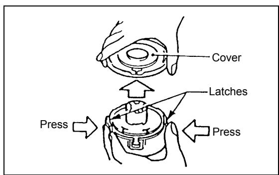
Replacing the nylon cord
- Stop the engine.
- Press the housing latches inward to lift off the cover, then remove the spool.


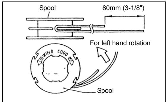
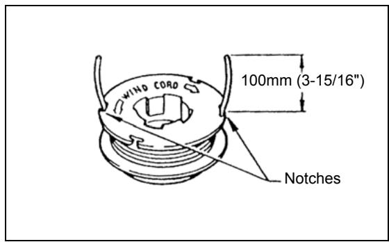
- Hook the center of new nylon cord into the notch in the center of the spool, with one end of the cord extending about 80mm (3-1/8") more than the other. Then wind both ends firmly around the spool in the direction of the head rotation (left-hand direction indicated by LH and right-hand direction by RH on the side of the spool).
-
Wind all but about 100mm (3-15/16") of the cords around the spool, leaving the ends temporarily hooked through the notch on the side of the spool.
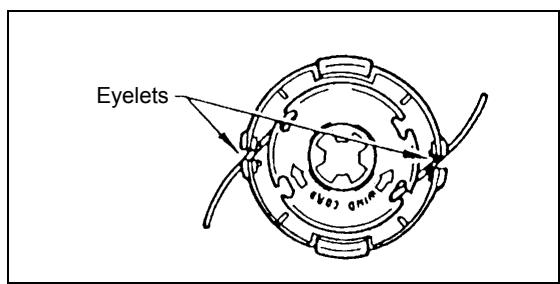
-
Mount the spool in the housing so that the grooves and protrusions on the spool match up with those in the housing. Mount the spool so that the writing on the spool is visible from above. Next, unhook the ends of the cords from their temporary position, and feed the cords through the eyelets so that they protrude from the housing.
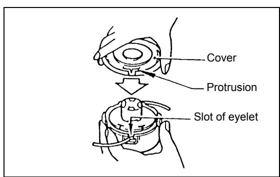
- Align the protrusion on the underside of the cover with the slots of the eyelets. Then push cover firmly onto the housing to secure it.
Servicing instructions
Servicing instructions
CAUTION: Before performing any type of maintenance work on the Brush cutter, always switch off the motor and detach the plug cap from the spark plug (see "checking the spark plug"). Always wear protective gloves.
CAUTION: Never remove the recoil starter yourself. Doing so may cause an accident. This procedure should only be performed by an Authorized Service Agent.
To ensure a long service life and to avoid any damage to the equipment, perform the following maintenance operations regularly.
Daily inspection and maintenance
- Before operation, check the equipment for loose screws or missing parts. Pay particular attention to the tightness of the cutter blade or nylon cutting head.
- Before operation, always check to make sure that the cooling air passage and cylinder fins are not clogged. Clean them if necessary.
-
Perform the following maintenance operations daily after use:
-
Clean the Brush cutter externally and inspect it for damage.
- Clean the air filter. When working under extremely dusty conditions, clean the filter several times a day.
- Check the blade or the nylon cutting head for damage and make sure it is firmly mounted.
- Check that there is sufficient difference between the idling and operating speeds to ensure the cutting tool is at a standstill while the engine is idling (if necessary, reduce the idling speed).
If the cutting tool continues to rotate during engine idling, consult your nearest Authorized Service Agent.
- Check that the I-O switch, the lock-off lever, the control lever, and the lock button are all functioning correctly.

Cleaning the air cleaner (filter)
- Unscrew screw (1).
- Turn the choke lever (4) to the fully closed side, and keep the carburetor away from any dust or dirt.
- Remove the air cleaner cover (3).
- Remove the sponge element (2), wash it in lukewarm water and dry it completely.
- After cleaning, put back the air cleaner cover (3) and fasten it with screw (1).
NOTE: If there is excessive dust or dirt adhering to the air cleaner, clean it every day. A clogged air cleaner may make it difficult or impossible to start the engine, or may increase the engine rotational speed.
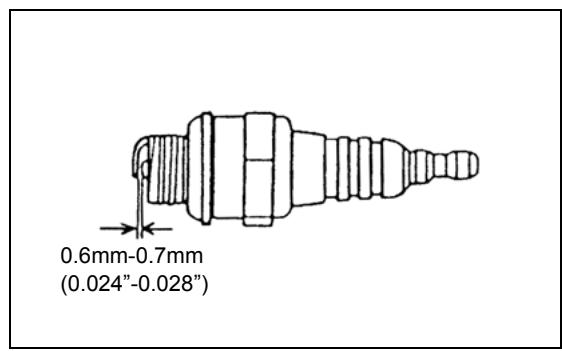
Checking the spark plug
- Only use the supplied universal wrench to remove or to install the spark plug.
- The gap between the two electrodes of the spark plug should be 0.6-0.7mm (0.024"-0.028"). If the gap is too wide or too narrow, adjust it. If the spark plug is clogged with carton or dirty, clean it thoroughly or replace it.
CAUTION: Never touch the spark plug connector while the engine is running (danger of high voltage electric shock).
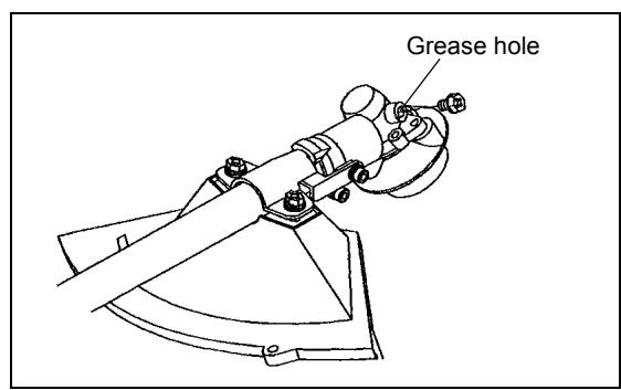
Supply of grease to gear case
- Supply grease (Shell Alvania 3 or equivalent) to the gear case through the grease hole every 30 hours. (Genuine MAKITA grease may be purchased from your MAKITA dealer.)
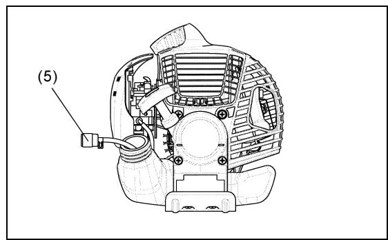
Suction head in the fuel tank
- The fuel filler (5) of the suction head is used to supply the fuel required by the carburetor.
- Visually inspect the fuel filter periodically. To inspect the filter, open the tank cap, use a wire hook and pull out the suction head through the tank opening. Replace the filter if it has hardened, become particularly dirty, or clogged.
- Insufficient fuel supply may result in the maximum permissible speed being exceeded. Therefore, the fuel filter must be replaced at least quarterly to ensure satisfactory fuel supply to the carburetor.
Any other maintenance or adjustment work that is not described in this manual must only be performed by Authorized Service Agents.
Storage
- When storing the equipment for a long period of time, drain all the fuel from the fuel tank and carburetor. To do this, simple drain all of the fuel from the fuel tank. Dispose of the drained fuel in accordance with local applicable laws.
- Remove the spark plug and add a few drops of oil into the spark plug hole. Then, pull the starter gently so that oil coats the inside of the engine, then tighten the spark plug.
- Clean any dirt or dust from the cutter blade and outside of the engine, and wipe them with a oil-immersed cloth. Store the equipment in a dry place.

Maintenance schedule
| General | Engine assembly, screws and nuts | Visual inspection for damage and tightness Check for general condition and security |
| After each refuelling | Control lever I-O switch | Functional check Functional check |
| Daily | Air filter Cooling air duct Cutting tool Idling speed | To be cleaned To be cleaned Check for damage and sharpness Inspection (cutting tool must not move) |
| Weekly | Spark plug Muffler | Inspection, replace if necessary Inspect, and clean the opening if necessary |
| Quarterly | Suction head Fuel tank | To be replaced To be cleaned |
| Shutting down procedure | Fuel tank Carburetor | Empty fuel tank Operate until engine runs out of fuel |
Troubleshooting
| Fault | System | Observation | Cause |
| Engine doesn't start, or is difficult to start | Ignition system | Ignition spark O.K. | Fault in fuel supply or compression system, mechanical defect |
| No ignition spark | I-O switch operated, wiring fault or short circuit, spark plug or connector defective, ignition module faulty | ||
| Fuel supply | Fuel tank filled | Incorrect choke position, carburetor defective, fuel supply line bent or blocked, fuel dirty. | |
| Compression | No compression when pulled over | Cylinder bottom gasket defective, crankshaft seals damaged, cylinder or piston rings defective or improper sealing of spark plug | |
| Mechanical fault | Starter not engaging | Broken starter spring, broken parts inside the engine | |
| Warm start problems | Tank filled. Ignition spark O.K. | Carburetor contaminated, must be cleaned | |
| Engine starts but dies | Fuel supply | Tank filled | Incorrect idling adjustment, carburetor contaminated |
| Fuel tank vent defective, fuel supply line interrupted, cable or I-O switch faulty | |||
| Insufficient performance | Several systems may simultaneously be affected | Engine idling poor | Air filter contaminated, carburetor contaminated, muffler clogged, exhaust duct in the cylinder clogged |

CE2008
Tomoyasu Kato
Director
Fabricant responsible :
Makita Corporation
3-11-8, Sumiyoshi-cho, Anjo, Aichi, JAPON
Representant agreé en Europe :
Makita International Europe Ltd.
Michigan Drive, Tongwell, Milton Keynes, Bucks MK15 8JD, ANGLETERRE
Correct mixture ratio:

CE2008
Tomoyasu Kato Director
Michigan Drive, Tongwell, Milton Kyenes, Bucks MK15 8JD, ENGLAND
Modello; DBC260U, DBC260L
3-11-8, Sumiyoshi-cho, Anjo, Aichi, GIAPPONE
Michigan Drive, Tongwell, Milton kyenes, Bucks MK15 8JD, INGHILTERRA
Dati tecnici DBC260U, DBC260L
Model; DBC260U, DBC260L

Tomoyasu Kato
Director
Michigan Drive, Tongwell, Milton Keynes, Bucks MK15 8JD, ENGELAND
Technische gegevens DBC260U, DBC260L

DBC260U
U-handgreeptype
De handgreep monteren
Zuigkop in brandstoftank
Modelo; DBC260U, DBC260L

CE2008
Tomoyasu Kato Director
Fabricante responsable:
Makita Corporation.
3-11-8, Sumiyoshi-cho, Anjo, Aichi, JAPON
Representante autorizzato en Europa:
Makita International Europe Ltd.
Michigan Drive, Tongwell, Milton kyenes, Bucks MK15 8JD, REINO UNIDO
DatasétécnicosDBC260U,DBC260L
Dados技术和 DBC260U, DBC260L 110
Nomes de peças 111
Montar a pega 112
Montar o protector. 113
Modelo; DBC260U, DBC260L
Michigan Drive, Tongwell, Milton Keynes, Bucks MK15 8JD, INGLATERRA
Dados&TecnicosDBC260U,DBC260L
Tekniske data for DBC260U, DBC260L 127
Delenes betegnelse 128
Model; DBC260U, DBC260L
Michigan Drive, Tongwell, Milton kyenes, Bucks MK15 8JD, ENGLAND
Tekniske data for DBC260U, DBC260L
Kontrol at taendroret
ENEPTOIOIHsH/EKKINHsH

ANENEPRONOIH/ΣTAMATHMA
O8nyies a0aalia
EviKec oynyic
MovTeλo: DBC260U, DBC260L
Eueuyn mac ot to npoiov auto oouopwvea ta akoloutheta npotuna twv tuonnoioevwv vrtunw, ISO11806, EN55012 ouuphiwa uic Odyiec nC Enitpornc, 89/392/EOK, tpononoioeyn 98/37/EOK, 93/68/EOK, tpononoioeyn 89/ 336/EOK.
MeTpneVn loxus Hyou:111,7 dB
Eyyunμενn Ioxuc Hxou: 114 dB
Michigan Drive, Tongwell, Milton kyenes, Bucks MK15 8JD, ENGLAND
TeXviKaδεδoμεva DBC260U, DBC260L