
KIT THERMO DIGI 24 HF - Thermostat FLASH - Free user manual and instructions
Find the device manual for free KIT THERMO DIGI 24 HF FLASH in PDF.
| Product type | Wireless programmable thermostat kit with wall receiver IP43 |
| Brand | FLASH |
| Model | KIT THERMO DIGI 24 HF |
| Transmitter dimensions | 115 x 82 x 34 mm |
| Receiver dimensions | 130 x 60 x 27 mm |
| Weight | Approximately 300 g (complete kit) |
| Transmitter power supply | 2 alkaline batteries 1.5 V LR6 (battery life 12 months) |
| Receiver power supply | 230 V +10% / -15% |
| Temperature setting ranges | Comfort, economy, frost protection: +5°C to +30°C |
| Room temperature display | 0°C to +40°C |
| Static differential | < 0.3°C |
| Radio frequency | 433.92 MHz |
| Radio range | 75 m in free field, 3 floors in typical housing |
| Transmitter protection rating | IP30 |
| Receiver protection rating | IP43 |
| Preset programs | 3 programs (P1, P2, P3) non-modifiable + 1 free program (P4) |
| Operating modes | Auto, Manual, Extended absence (frost protection), Temporary override |
| Regulation type | On/Off or Chronoproportional (selectable) |
| Special functions | Anti-sticking for circulation pump, factory coding transmitter/receiver |
| Receiver output | Potential-free changeover contact, switching capacity 16 A (resistive) / 3 A (inductive) |
| Transmitter operating temperature | 0°C to +40°C |
| Receiver operating temperature | -10°C to +60°C |
| Maintenance | Replace batteries when low battery indicator appears; clean with a dry cloth |
| Safety | Frost protection, insulation class II (receiver), impact resistance IK04 |
Frequently Asked Questions - KIT THERMO DIGI 24 HF FLASH
User questions about KIT THERMO DIGI 24 HF FLASH
0 question about this device. Answer the ones you know or ask your own.
Ask a new question about this device
Download the instructions for your Thermostat in PDF format for free! Find your manual KIT THERMO DIGI 24 HF - FLASH and take your electronic device back in hand. On this page are published all the documents necessary for the use of your device. KIT THERMO DIGI 24 HF by FLASH.
USER MANUAL KIT THERMO DIGI 24 HF FLASH
KitThermoflash DIGI 24 HF
réf. 56464
natural_image
Exterior view of a CD Flash device with two vertical connectors and a screen (no visible text or symbols)- Fixez le au mur.

natural_image
Diagram showing a mechanical component with two screws and a dashed line indicating a reference or alignment (no text or symbols present)natural_image
Illustration of a white cylindrical device with screwdriver and 'Flash' label, no text or symbols on the device itself
natural_image
White remote device with exposed internal components and ports, no visible text or symbols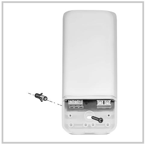
natural_image
White remote device with internal components and a small car icon pointing to its side (no text or symbols visible)
natural_image
White remote phone casing with 85 mm height dimension and handle, shown with dashed alignment lines (no text or symbols on the device itself)
natural_image
Exterior view of a CD Flash device with two vertical connectors (no text or symbols visible)natural_image
Diagram showing two screws inserted into a plastic housing, with a dashed line indicating the direction of insertion (no text or symbols present)natural_image
Illustration of a white cylindrical device with screwdriver and 'Flash' label, no text or symbols on the device itself
natural_image
White remote device with exposed internal components and ports, no visible text or symbols
natural_image
White remote device with internal components and a small car icon pointing to its side (no text or symbols visible)
natural_image
White remote control device with 85 mm height dimension标注 (no text or symbols on the device itself)


natural_image
Front view of a handheld electronic device labeled 'Flash' with two vertical connectors (no visible text or symbols on the device body)natural_image
Diagram of a mechanical component with two screws and a dashed line indicating alignment (no text or symbols)The image contains a series of identical, evenly spaced black dots arranged in a horizontal row. There is no text or mathematical content to process. Therefore, the correct OCR output is an empty string.
0 1 2 3 4 5 6 7 8 9 10 11 12 13 14 15 16 17 18 19 20 21 22 23 24
natural_image
Illustration of a white cylindrical device with screwdriver and 'Flash' label, no text or symbols on the device itself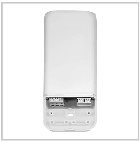
natural_image
White remote device with exposed internal components and ports, no visible text or symbols
natural_image
White remote device with internal components and a small car icon pointing to its side (no text or symbols visible)
natural_image
White remote phone casing with 85 mm height dimension and handle, shown with dashed alignment lines (no text or symbols on the device itself)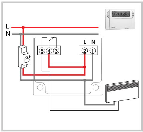


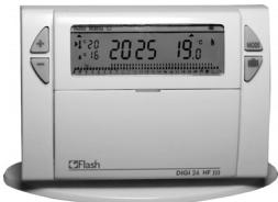
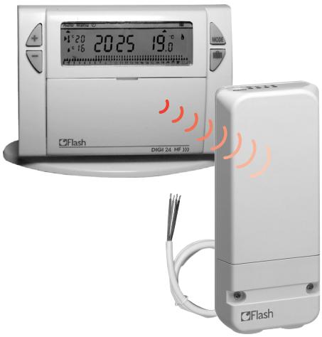
Wireless clock thermostat and wall-mounting receiver
Wireless clock thermostat, daily cycle and IP43 wall-mounting receiver


Le confort facile

Product presentation
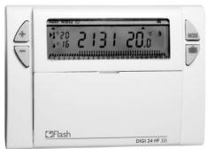
The thermostat DIGI 24 HF
Easy to install, easy to program, the kit DIGI 24 HF will allow you to control your heating system in accordance with your way of life.
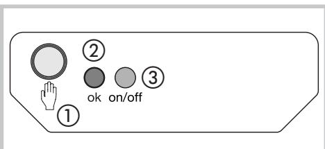
The IP43 wall-mounting receiver
The IP43 wall-mounting receiver can be easily installed close to the boiler. The thermostat DIGI 24 HF will control the ambient temperature in the dwelling and will transmit ON and OFF signals to the receiver.
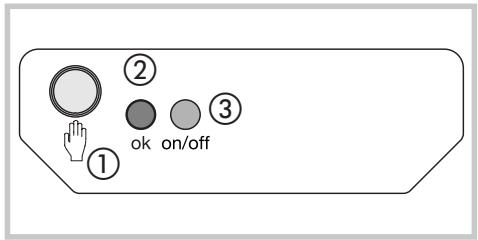
① Pushbutton for configuration and priority setting.
② Indicator of Power on and coding light. LED on = product is powered on. This LED flickers during coding operations.
③ Operation indicator light.
The LED is on when receiver's output contact is closed = ON.
Important: the transmitter and receiver assembly is factory coded and is therefore immediately operational.
There is no need to recode.
▶ Inserting or re-inserting the batteries
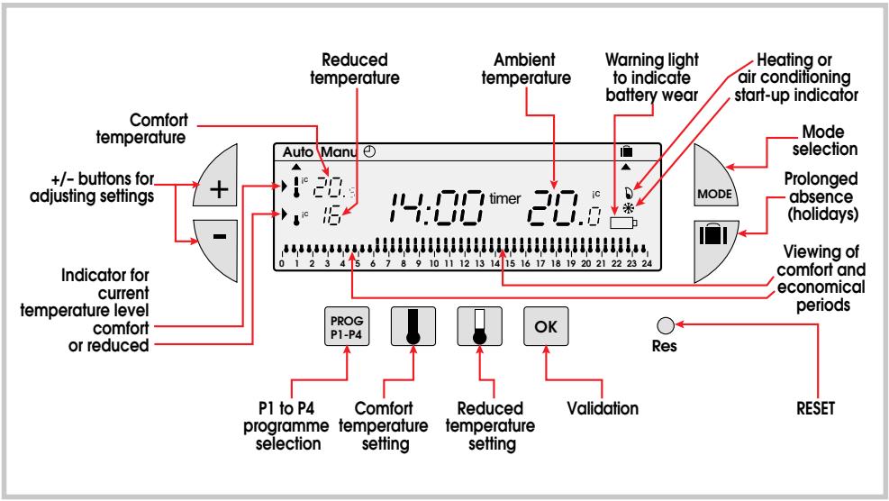
This clock thermostat is equipped with a warning light to indicate when the batteries need replacing. As soon as this indicator lights up at the bottom right-hand side of the display panel, replace the batteries (use two 1.5V LR6 alkaline batteries, life is approximately 12 months).
The device remains programmed for 60 seconds while batteries are being replaced.
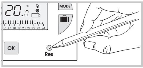
Reset
Before beginning the programming of the device, please slide cover down and press RESET with the tip of a pen.
The Thermoflash DIGI 24 HF kit has been designed to offer you comfort and energy savings. It will be easily installed in your home and will control the ambient temperature according to the program. It will control through radio waves the RF receiver which may be fitted close to the boiler or the heating system.
The Thermoflash DIGI 24 HF kit will control the ambient temperature according to 3 temperature levels.
- Comfort temperature: this is the temperature for your hours of presence.
- Reduced temperature: this is the temperature for your brief absences or during the night.
- Frost protection temperature: this is the minimum temperature for long absences. It protects your dwelling from the risk of frost.
Installation of thermoflash DIGI 24 HF
To control accurately the ambient temperature, the DIGI 24 HF must be installed 1,5 m. above the floor, on an internal wall shaded from direct sunlight and from all thermal influences such as: television, lamps, heater, etc.
The DIGI 24 HF is delivered with a base. With this accessory, you can simply put it on a furniture. It is important to check that no external influence will perturb it (heater, window etc.).
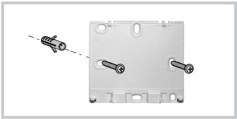
You can also install it on an internal wall.
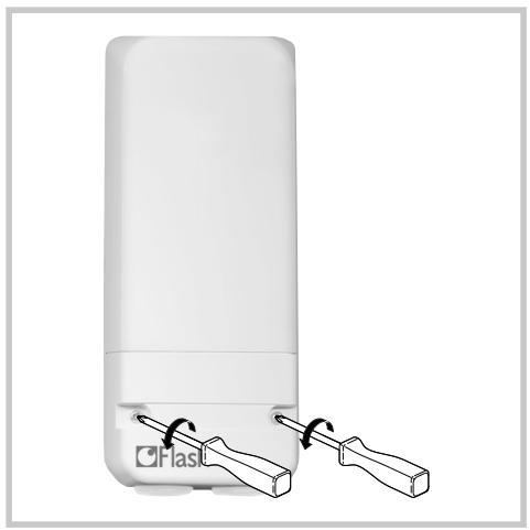
• Therefore, take out its wall mounting base.
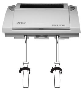
natural_image
Exterior view of a CD Flash device with two vertical connectors (no text or symbols visible)- Fix it to the wall.
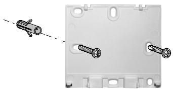
natural_image
Diagram of a mechanical component with two screws and a dashed line indicating a reference or alignment (no text or symbols present)- Then replace the product on its base.
Setting current time
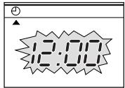
You are putting the device into operation for the first time.
- You have just pressed the RESET button.
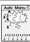
• 12:00 appears and the pointer ▲ flashes.
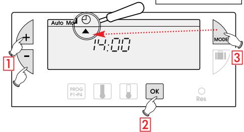
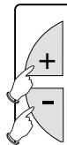
1 Set the time using the +/- buttons (the numbers run off more quickly when the button is pressed continuously).
2 Validate with the OK button.
3 If you wish to change the time or the day, press the MODE button until the pointer ▲ under the clock sign and continue as above for points ① and ②.
Temperature setting
Comfort and reduced temperatures are pre-set: Comfort = 20°C, Reduced = 16°C.
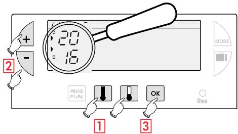
Modification of comfort temperature
1 Press the 🔊 button.
2 Modify the temperature with the +/- buttons.
3 Validate with the OK button.
Modification of reduced temperature
1 Press the 🔍 button.
2 Modify the temperature with the +/- buttons.
3 Validate with the OK button.
Programming PROG P1-P4
You can programme your DIGI 24 HF according to 4 programme settings: P1, P2 and P3 are prerecorded and cannot be modified. P4 is blank and allows you to create a personalized programme.
PI = Comfort temperature from 6 a.m. till 11 p.m. Reduced temperature from 11 p.m. till 6 a.m.
0 1 2 3 4 5 6 7 8 9 10 11 12 13 14 15 16 17 18 19 20 21 22 23 24
PI is the default allocation. If this corresponds to your life style, stay in automatic mode, otherwise, continue.
P2 = Comfort temperature from 6 a.m. till 8.30 a.m. and from 4.30 p.m. till 11 p.m. Reduced temperature from 8.30 a.m. till 4.30 p.m. and from 11 p.m. till 6 a.m.
0 1 2 3 4 5 6 7 8 9 10 11 12 13 14 15 16 17 18 19 20 21 22 23 24
P3 = Comfort temperature from 6 a.m. till 8.30 a.m., from 11.30 a.m. till 1.30 p.m. and from 4.30 p.m. till 11 p.m. Reduced temperature from 8.30 a.m. till 11.30 a.m. from 1.30 a.m. till 4.30 p.m. and from 11 p.m. till 6 a.m.
0 1 2 3 4 5 6 7 8 9 10 11 12 13 14 15 16 17 18 19 20 21 22 23 24
P4 = Blank programme allowing you to create 3 comfort temperature periods and 3 reduced periods.
Selection of an existing P1, P2 or P3 programme (in programming mode all modifications are automatically validated).
example : P2
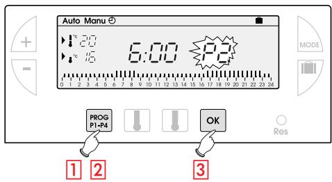
1 Press the PROG P1-P4 button to go into programming mode.
The N° of the programme assigned to the day flashes on the right-hand side of the display panel.
2 Press the PROG P1-P4 button until the P2 programme number flashes in the right side of the screen.
3 Validate with the OK button.
Creating a P4 programme
A 24-hour profile composed of 48 thermometers at the bottom of the display panel allows your programme composition to be easily viewed;
A half-empty thermometer corresponds to 30 minutes at reduced temperature.
A full thermometer corresponds to 30 minutes at reduced temperature.
example: programming 3 temperature periods: 6 a.m. till 8 a.m., noon till 2 a.m. and 6 a.m. till 22 a.m.
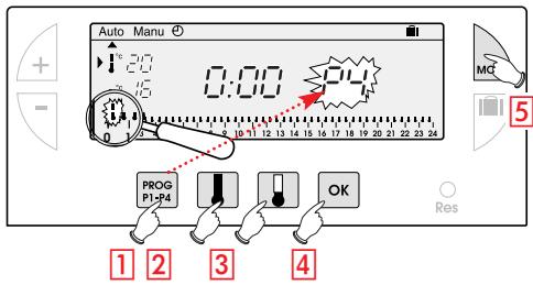
From the Auto, mode press the PROG PI-P4 button.
2 Press the PROG P1-P4 button until the P4 programme number flashes in the right side of the screen. Your display panel indicates time as 0:00 and the first thermometer flashes on the 24-hour profile.
3 Press the 📁 button several times to obtain 6:00 :The time displayed advances by 30 minutes for each short press. Continuous pressing accelerates the time run-off.
- Press the ⚠ button several times to obtain 8:00.
- Press the 🖱️ button several times to obtain 12:00.
- Press the ⚠ button several times to obtain 14:00.
- Press the 🖱 button several times to obtain 18:00.
- Press the ⚠ button several times to obtain 22:00.
N.B.: if you make a mistake (e.g. 11.30 instead of 12.00) use the +/- buttons to advance or return and correct with the thermometer buttons.
4 Validate with the OK button.
5 Press the MODE button to return to Auto mode.
Programme reading
You can check your programming:

1 From Auto mode, press the PROG PI-P4 button.
0 1 2 3 4 5 6 7 8 9 10 11 12 13 14 15 16 17 18 19 20 21 22 23 24
2 Press the MODE button to return in Auto mode.
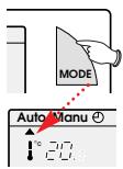
Automatic mode (Auto)
You pass into automatic mode by pressing the MODE button until the pointer ▲ appears under Auto.
In automatic mode the clock thermostat adapts to your life style by running the programs you have selected.
Manual mode (Manu)
Manual mode transforms your device into a simple thermostat.
It allows you to maintain a constant temperature in your dwelling (set to a temperature of between 5^ C and 30^ C).
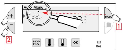
1 Press the MODE button to position the pointer ▲ under Manu.
2 Press the + or - buttons to adjust to the desired temperature (for instance 22.5^ C).
To quit the Manu mode, press the MODE button and re-position ▲ under Auto.
Temporary modification
temperature
In automatic mode this very useful function allows you to modify ambient temperature temporarily.
- To increase the temperature, press the + button (several times, if necessary).
- To decrease the temperature press the - button (several times, if necessary).
The current temperature level indicator (comfort or reduced) will begin flashing. This modification ends with the next change in programmed temperature.
To return to the initial programme press MODE and re-position the pointer ▲ under Auto.
The current temperature level indicator (comfort or reduced) will stop flashing when the temporary modification comes to an end.
Prolonged absence mode (holidays)
This mode protects your dwelling from freezing by maintaining a minimum adjustable temperature in your dwelling during your absences.
You can programme the length of your absence so that the temperature rises for your return.
2 different settings are available for maintaining temperature above frost level:
Permanent frost protection
- Press the 📄 button, the day 🔊 flickers.
- Press once the - button, the F_ORC display flickers.
- Validate with the OK button.
- Using +/- buttons, set the temperature level desired during your absence.
- Validate with the OK button.
To cancel and return to Auto mode, press MODE button.
Setting frost protection temperature for a certain number of days
- Press the 📄 button, the day 🔊 flickers.
- Using +/- buttons, set the length of your absence in days (from 1 to 99 days). The current day count as one.
- Validate with the OK button.
- Using +/- buttons, set the temperature level desired during your absence.
- Validate with the OK button.
To cancel and return to Auto mode, press MODE button.
Possible settings
Various settings can be made on the back of the device (when it is not mounted).
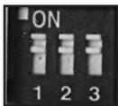
1- Selection of installation's type

2- Selection of adjustment mode

The proportional mode is to be set when using floorheating (high inertia).
3- Anti-locking function for the circulation pump (activation of the pump for 1 minute every 24 hours)


Configuration
In order to associate the transmitter with the receiver:
- Press the receiver's ① pushbutton for more than 3 seconds.
- The indicator OK ② light will start flickering, release the pushbutton. The system is in configuration mode.
- Press the RESET button during 3 seconds of the transmitter Thermoflash DIGI 24 HF.
- The indicator OK ② button will stop flickering, at the end of 5 seconds.
The transmitter/receiver link is now established.
Reset
For clearing all transmission/reception links:
- Press the receiver's pushbutton ① for more than 10 seconds.
- The indicator OK ② light flickers slowly, then more quickly.
- Press again the receiver's pushbutton ① more than 3 seconds.
- The indicator OK ② light stops flickering, all links have been cleared.
The receiver returns to the Auto mode.
Priority setting
Manual control is provided for this product.
- Press shortly receiver's ① pushbutton (<3 sec). Each press reverses output state.
Note: radio control retains priority.
Troubleshootings
• The heating does not start:
- receiver's power supply is cut off (OK ② light is off). Check fuse and circuit breaker.
- Receiver is outside of transmitter's range:
- move transmitter closer to receiver.
- Receiver does not recognize transmitter's code:
- re-install receiver.
- The system does not start or does not stop:
- the receiver or transmitter is disturbed by radio transmission (radio ham, TV monitor, cellular phone re-transmitter, etc.): attempt to remove the source of disturbance.
In case of persistent problem, call on your electrician.
Technical specifications
Transmitter
Adjustment range for comfort temperature:
$$ + 5 ^ {\circ} \mathrm{C} \text { to } + 3 0 ^ {\circ} \mathrm{C} $$
Adjustment range for reduced temperature:
$$ + 5 ^ {\circ} \mathrm{C} \text { to } + 3 0 ^ {\circ} \mathrm{C} $$
Adjustment range for frost protection temperature:
$$ + 5 ^ {\circ} \mathrm{C} \text { to } + 3 0 ^ {\circ} \mathrm{C} $$
Display range for ambient temperature:
$$ 0 ^ {\circ} \mathrm{C} \text { to } + 4 0 ^ {\circ} \mathrm{C} $$
Static differential:
$$ < 0. 3 \mathrm{K} $$
Power: 2 standard LR6 alkaline batteries (to supply the product and the radio transmission)
Operating range: 75 m from transmitter to receiver in a free field (operates over 3 building floors)
Transmission frequency: 433.92 MHz
Transmitter duty cycle: 10% IP: 30
Operating temperature: 0^ C to +40^ C
Storage temperature: -20^ to +70^
Hygrometry: 95% max. at 25°C
Dimensions: 115 x 82 x 34 mm
Degree of pollution: standard
Standards: EN 301-489-3
Receiver
Supply voltage: 230V +10 % at -15 %
Minimum load: 12 V 100 mA
Output: I changeover contact free of potential
Switching capacity:
$$ \mathrm{ACI}: \quad 1 6 \mathrm{A} 2 5 0 \mathrm{V} $$
Inductive: 3 A (cos φ = 0,6)
Radio frequency: 433.92 MHz
Degree of protection: IP43
Isolation class: II
Mechanical protection: IK04
Operating temperature: -10^ to +60^
Storage temperature: -20^ to +70^
Flexible capacity: 0,5 to 1,5 mm ^4
Rigid capacity 0,5 to 2,5 mm ^4
Dimensions: 130 × 60 × 27 mm
Hygrometry: 90% max. at 20°C
Receiver class: 2
Standards: EN 60669-2-1
Standards: EN 300220-3,
EN 301-489-1 and EN 301-489-3.
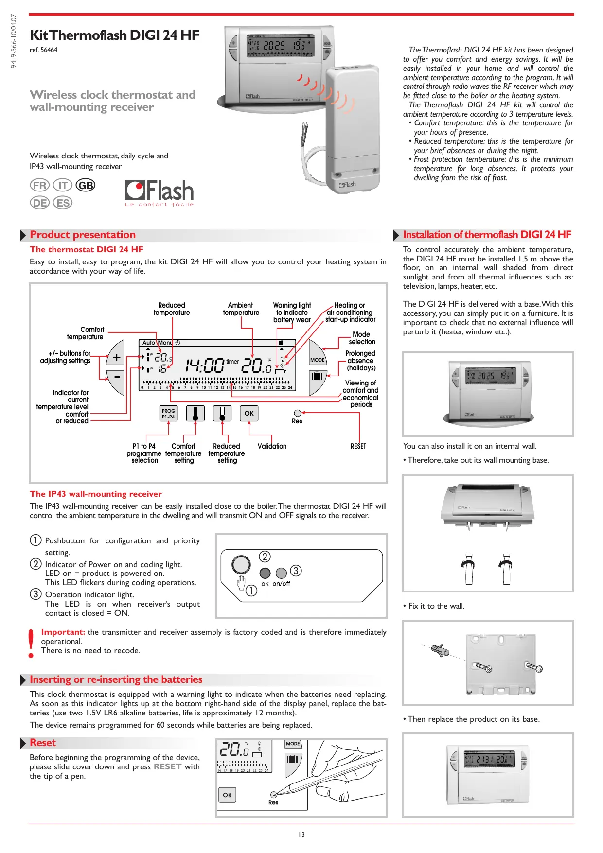
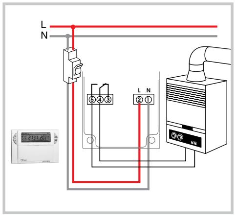
Receiver installation
Before working on the installation, isolate all electrical supplies. All electrical wiring must be carried out by a qualified person.
For easier installation, the Thermoflash DIGI 24 HF kit is supplied with a flexible 4-wire 1.5 mm ^2 cable of 1.20m length (not connected).
We recommend using this cable for connecting the HF receiver according to the following colour codes:
$$ \text { brown } = \text { phase } $$
$$ \text { blue } = \text { neutral } $$
gray black} connection to the boiler
natural_image
Illustration of a white cylindrical device with screwdriver and LED, connected by a screwdriver (no text or symbols)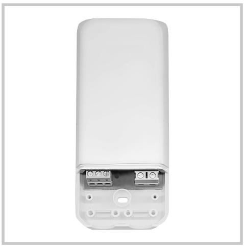
natural_image
White remote control device with exposed internal components and terminal ports (no text or symbols visible)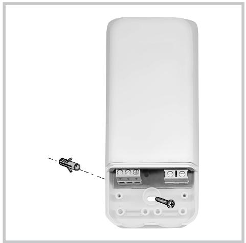
natural_image
White remote device casing with internal components and a dashed line indicating a cable or connector (no text or symbols visible)
natural_image
White remote control device with 85 mm height dimension and screwdriver on top (no text or symbols)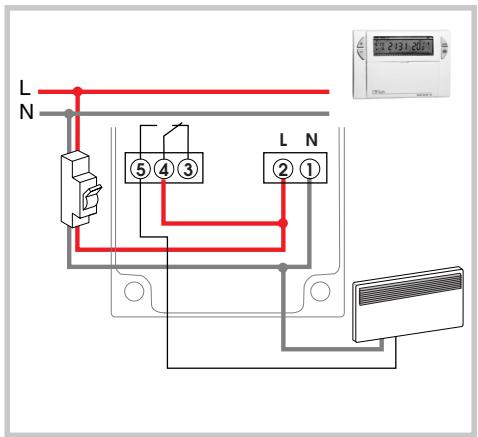


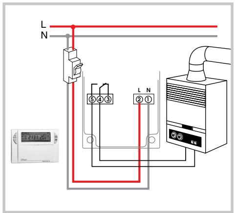
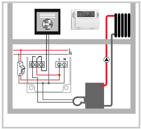
When two appliances (heating and cooling) are connected, always keep one of them switched off to prevent their simultaneous operation during the same season.
KitThermoflash DIGI 24 HF
ref. 56464
Termostato programable y receptor mural
Termostato programable sin hilos, ciclo diario y receptor mural IP43


Le confort facile
El receptor mural IP 43
natural_image
Exterior view of a CD Flash device with two vertical connectors (no text or symbols visible)- Fijarlo a la pared.
natural_image
3D diagram of a mechanical component with two screws and a dashed line indicating alignment (no text or symbols)natural_image
Illustration of a white cylindrical device with screwdriver and 'Flash' label, no text or symbols on the device itself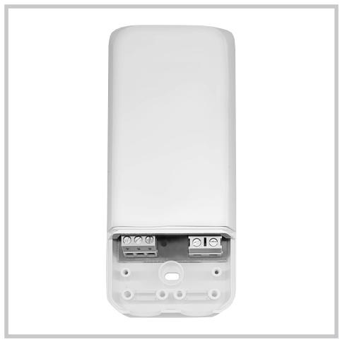
natural_image
White remote device with exposed internal components and ports, no visible text or symbols
natural_image
White remote device with internal components and a small car icon pointing to its side (no text or symbols visible)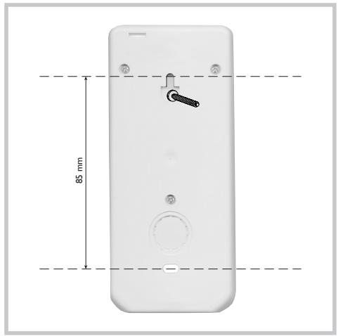
natural_image
White remote phone rear panel with 85 mm height dimension and handle (no text or symbols on body)
- KitThermoflash DIGI 24 HF
- Wireless clock thermostat and wall-mounting receiver
- Product presentation
- The thermostat DIGI 24 HF
- The IP43 wall-mounting receiver
- ▶ Inserting or re-inserting the batteries
- Reset
- Installation of thermoflash DIGI 24 HF
- Setting current time
- Temperature setting
- Modification of comfort temperature
- Modification of reduced temperature
- Programming PROG P1-P4
- Creating a P4 programme
- Programme reading
- Automatic mode (Auto)
- Manual mode (Manu)
- Temporary modification
- temperature
- Prolonged absence mode (holidays)
- different settings are available for maintaining temperature above frost level:
- Permanent frost protection
- Setting frost protection temperature for a certain number of days
- Possible settings
- 1- Selection of installation's type
- 2- Selection of adjustment mode
- 3- Anti-locking function for the circulation pump (activation of the pump for 1 minute every 24 hours)
- Configuration
- Priority setting
- Troubleshootings
- Technical specifications
- Transmitter
- Receiver
- Receiver installation
- Termostato programable y receptor mural
- El receptor mural IP 43
Brand : FLASH
Model : KIT THERMO DIGI 24 HF
Category : Thermostat