USER MANUAL THERMO DIGI 2 HF FLASH
Kit THERMOFLASH DIGI 2 HF
La programmation [PROG] [P1-P4]
![FLASH THERMO DIGI 2 HF - La programmation [PROG] [P1-P4] - 1](/content/2025/01/138552/images/42ab510eff3f37dfbdcacbbdc42ba33d5958dbf69731c6a4bd35df3beb29fc2a.jpg)
Pour programmermeurresemainevouddiposezde 4programmes:
Kit THERMOFLASH DIGI 2 HF
![FLASH THERMO DIGI 2 HF - La programmation [PROG] [P1-P4] - 2](/content/2025/01/138552/images/ff312bd6ac669412e1ddaa512c81dbb63332b5bb2b8b78ac305cbe88ef462d74.jpg)
Kit THERMOFLASH DIGI 2 HF
![FLASH THERMO DIGI 2 HF - La programmation [PROG] [P1-P4] - 3](/content/2025/01/138552/images/4addca9738aeade64fb576d514e9cfbba1ffa7281fcf817119682510d7b93b05.jpg)
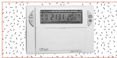
Kit Thermoflash Digi 2 RF.
Wireless clock thermostat
Weekly cycle
And IP43 wall mounting receiver.
Easy to install, easy to program, the RF Digi 2 will allow you to control your heating system in accordance with your way of life.
![FLASH THERMO DIGI 2 HF - La programmation [PROG] [P1-P4] - 4](/content/2025/01/138552/images/13f6361d3c0efdd54a80fa7bd8fd94583a000c7eea4648dcf2ab62e0b8474203.jpg)
The RF Digi 2 has been designed to offer you comfort and energy savings. It will be easily installed in your home and will control the ambient temperature according to the program. It will control through radio waves the RF receiver which may be fitted close to the boiler or the heating system.
The RF Digi 2 will control the ambient temperature according to 3 temperature levels.
- "comfort" temperature: this is the temperature for your hours of presence.
- "reduced" temperature : this is the temperature for your brief absences or during the night.
- "frost protection" temperature : this is the minimum temperature for long absences. It protects your dwelling from the risk of frost.
![FLASH THERMO DIGI 2 HF - La programmation [PROG] [P1-P4] - 5](/content/2025/01/138552/images/ff74e99e80197cbeb6c21d2a05dcfee8e476a3d235d37371733b909e7acd1fc0.jpg)
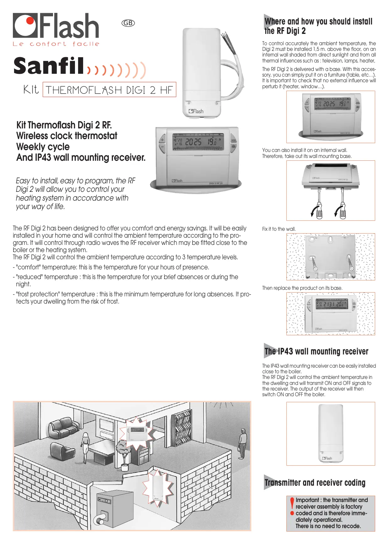
Where and how you should install the RF Digi 2
To control accurately the ambient temperature, the Digi 2 must be installed 1.5m above the floor, on an internal wall shaded from direct sunlight and from all thermal influences such as: television, lamps, heater,
The RF Digi 2 is delivered with a base. With this accessory, you can simply put it on a furniture (table, etc...). It is important to check that no external influence will perturb it (heater, window...).
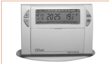
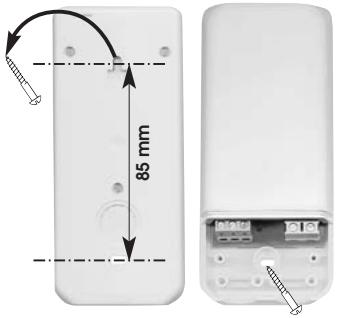
You can also install it on an internal wall. Therefore, take out its wall mounting base.
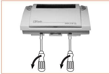
Fix it to the wall.
Then replace the product on its base.
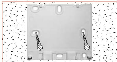
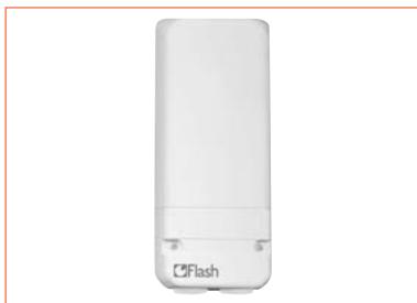
The IP43 wall mounting receiver
The IP43 wall mounting receiver can be easily installed close to the boiler.
The RF Digi 2 will control the ambient temperature in the dwelling and will transmit ON and OFF signals to the receiver. The output of the receiver will then switch ON and OFF the boiler.
Transmitter and receiver coding
Important: the transmitter and receiver assembly is factory coded and is therefore immediately operational. There is no need to recode.
CONTENTS
1 Inserting or re-inserting the batteries
Setting to current time and day
3 Temperature setting
4 Programming
5 Programme reading
"Auto" automatic mode
7 "Manu" manual mode
8 Temporary temperature modification
Prolonged absence mode (holidays)
10 Your installation maintenance signal
11 Installer's guide

Inserting or re-inserting the batteries
This clock thermostat is equipped with a warning light to indicate when the batteries need replacing. As soon as this indicator lights up at the bottom right-hand side of the display panel, replace the batteries (use two 1.5V UR6 alkaline batteries - life is approximately 12 months): The device remains programmed for 60 seconds while batteries are being replaced.
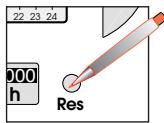
Before beginning the programming of the device, please slide cover down and press RESET with the tip of a pen.

Setting current time and day
- You are putting the device into operation for the first time.
- You have just pressed the RESET button (see above).
- "12:00" appears and the pointer flashes under day 1.
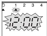
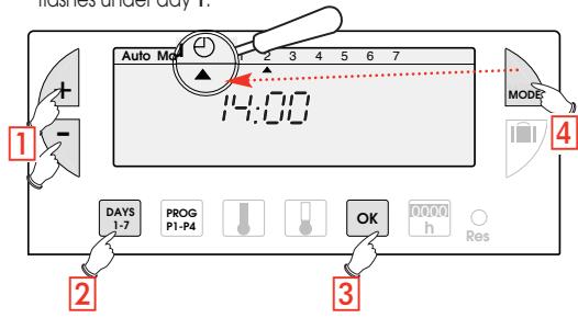
1 Set the time using the + / - buttons (the numbers run off more quickly when the button is pressed continuously).
Set the current day by pressing several times on the 1-7 button. A pointer appears under the corresponding day (1=Monday, 2=Tuesday, 3=Wednesday, etc.)
3 Validate with the OK button
4 If you wish to change the time or the day, press the MODE button until the pointer appears under the clock sign and continue as above for points 1, 2 and 3.
Functions and program of the RF Digi 2
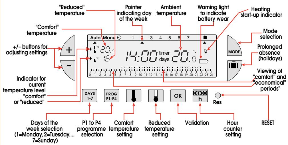

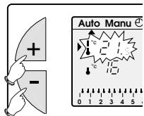
Temperature setting
Comfort and reduced temperatures are pre-set: Comfort = 20^ Reduced = 16^ .
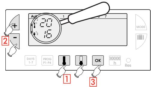
Modification of comfort temperature
Press the comfort button
2 Modify the temperature with the + / - buttons
3 Validate with OK
Modification of reduced temperature
Press the reduced button
2 Modify the temperature with the +/- buttons
3 Validate with OK

Programming

You can programme your week according to 4 programme settings:
P1, P2, P3 are pre-recorded and cannot be modified.
P4 is blank and allows you to create a personalized programme varying according to the day of the week.
P1 = Comfort temperature from 6 a.m. till 11 p.m. Reduced temperature from 11 p.m. till 6 a.m.
0 1 2 3 4 5 6 7 8 9 10 11 12 13 14 15 16 17 18 19 20 21 22 23 24
The standard allocation of P1 is to 7 days of the week. If this corresponds to your life style, stay in automatic mode. Otherwise, continue.
P2 = Comfort temperature from 6 a.m. till 8.30 a.m. and from 4.30 p.m. till 11 p.m. Reduced temperature from 8.30 a.m. till 4.30 p.m. and from 11 p.m. till 6 a.m.
0 1 2 3 4 5 6 7 8 9 10 11 12 13 14 15 16 17 18 19 20 21 22 23 24
P3 = Comfort temperature from 6 a.m. till 8.30 a.m., from 11.30 a.m. till 1.30 p.m. and from 4.30 p.m. till 11 p.m. Reduced temperature from 8.30 a.m. till 11.30 a.m., from 1.30 p.m. till 4.30 p.m. and from 11 p.m. till 6 a.m.
0 1 2 3 4 5 6 7 8 9 10 11 12 13 14 15 16 17 18 19 20 21 22 23 24
P4 = Blank programme allowing you to create 3 comfort temperature periods and 3 reduced periods for each day of the week.
Selection of an existing P1, P2 or P3 programme for a day of the week (in programming mode all modifications are automatically validated).
Example - P2 for Wednesday
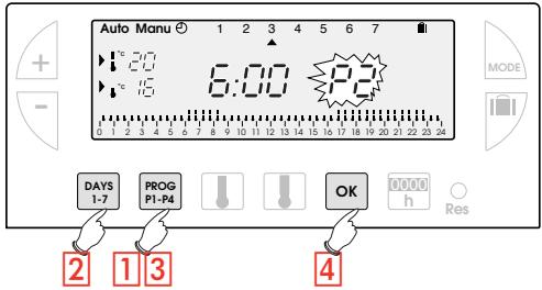
Press the PROG P1-4 button to go into programming mode. The N° of the programme assigned to the day flashes on the right-hand side of the display panel.
Press the DAYS 1-7 button until the pointer appears under the day you wish to programme (Wednesday in our example).
3 Press the PROG P1-P4 button until the P2 programme number flashes in the right side of the screen.
4 Press the OK button to validate. The following day is automatically proposed.
Creating a P4 programme
A 24-hour profile composed of 48 thermometers at the bottom of the display panel allows your programme composition to be easily viewed.
A half-empty thermometer corresponds to 30 minutes at reduced temperature.
A full thermometer corresponds to 30 minutes at comfort temperature.
Example - programming 3 temperature periods for Friday: 6 a.m. till 8 a.m., noon till 2 p.m. and 6 p.m. till 10 p.m.
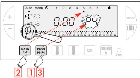
1 From the "Auto" mode press the PROG P1-P4 button
Press the DAYS 1-7 button until a pointer appears under the day you wish to programme (Friday in our example).
3 Press the PROG P1-P4 button until the P4 programme number flashes in the right side of the screen. Your display panel indicates time as 00:00 and the first thermometer flashes on the 24-hour profile.
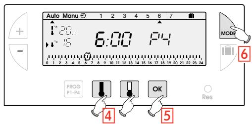
4 Press the button several times to obtain 6:00. The time displayed advances by 30 minutes for each short press. Continuous pressing accelerates the time run-off.
- Press the button several times to obtain 8:00.
- Press the button several times to obtain 12:00.
- Press the button several times to obtain 14:00.
- Press the button several times to obtain 18:00.
- Press the button several times to obtain 22:00
N.B. If you make a mistake (e.g. 11:30 instead of 12:00) use the + and - buttons to advance or return and correct with the and thermometer buttons.
Press the "OK" button. The following day automatically appears.
6 Press MODE to return to automatic mode.

Programme reading
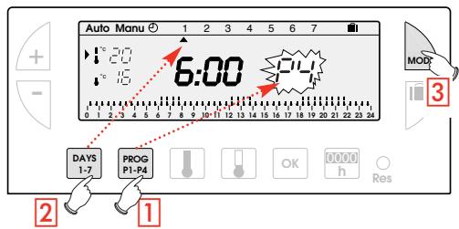
You can check your programming.
1 From "Auto" mode press the "PROG P1-P4" button.
2 With the "DAYS 1-7" button select the day from 1 to 7 and check your programming on the 24-hour profile at the bottom of the display panel (see example above).
0 1 2 3 4 5 6 7 8 9 10 11 12 13 14 15 16 17 18 19 20 21 22 23 24
3 Press "MODE" to return to automatic mode.
15 16 17 18 19 20 21 22 23 24

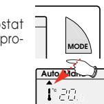
"Auto" automatic mode
You pass into automatic mode by pressing the "MODE" button until the pointer appears under "Auto".
In automatic mode the clock thermostat adapts to your life style by running the programs you have selected.

"Manu" Manual mode
Manual mode transforms your device into a simple thermostat. It allows you to maintain a constant temperature in your dwelling (set to a temperature of between 5^ and 30^ ).
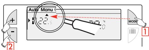
1 Press the "MODE" button to position the pointer under "Manu".
2 Press + or - to adjust to the desired temperature (for instance 22.5^ ). To quit the "Manu" mode, press "MODE" and re-position the pointer under "Auto".

Temporary temperature modification
In automatic mode this very useful function allows you to modify ambient temperature temporarily.
- To increase the temperature, press the + button (several times, if necessary).
-To decrease the temperature, press the - button (several times, if
into a simple thermostat. Temperature in your dwell 5^ and 30^ .
The current temperature level indicator (comfort or reduced) will begin flashing.
This modification ends with the next change in programmed temperature.
To return to the initial programme press "Mode" and re-position the pointer under "Auto".
The current temperature level indicator (comfort or reduced) will stop flashing when the temporary modification comes to an end.

Prolonged absence mode (holidays)
This mode protects your dwelling from freezing by maintaining a minimum adjustable temperature in your dwelling during your absences (from 1 to 99 days).
You can programme the length of your absence so that the temperature rises for your return.
2 different settings are available for maintaining temperature above frost level:
1 Permanent frost protection.
Press The day 01 flickers.
Press once The "Forc"

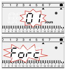
Validate with OK Using + keys, se
temperature level desired during your absence.
Validate with OK
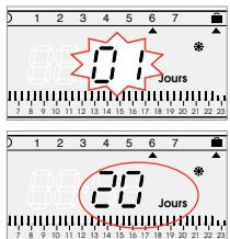
2 Setting frost protection temperature for a certain number of days.
Press The day 01 flickers.
Using + keys set the length of your absence in days (from 1 to 99 days). The current day count as one.
Validate with OK
Using keys, set the
temperature level desired during your absence.
Validate with OK
To cancel and return to automatic Mode, press


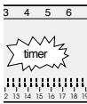
Installation maintenance signal [h]
This mode allows you either:
- to take steps for regular maintenance (change of air conditioning filter, device cleaning)
or
- to compare your heating or air conditioning consumption from one year to the next (by comparing the number of running hours).
![FLASH THERMO DIGI 2 HF - Installation maintenance signal [h] - 1](/content/2025/01/138552/images/eb581ae97b84ca37f0828eb364105a8f86905344ca3e5fc53bf9b205c80fb3b1.jpg)
Counting running hours
Press the "00:00" button. The display panel will indicate the number of hours your burner, air conditioning, ventilator-convector, etc. (depending of the type of device controlled) has been running from the moment the batteries were inserted.
(By pressing once on + or - you return the counter to zero.)
2 Press "MODE" to return to automatic mode.
Programming the regular servicing of your installation.
1 Press the "00:00" time button.
2 Set the number of running hours after which the warning signal should flash using the + and - buttons.
3 Validate with the "OK" button: The countdown begins. The message "timer" will appear at the end of the count-down warning you that servicing is required.

Possible settings
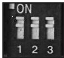
POSSIBLE SETTINGS
Various settings can be made on the back of the device (when it is not mounted).
Strap 1 Anti-locking function for the circulation pump (activation of the pump for 1 minute every 24 hours).

Anti-locking function off

Anti-locking function on

Selection of adjustment mode

ON / OFF

Proportional

lets you shift to HF configuration mode

Automatic mode

Configuration mode with HF receiver(s)
Technical data
RF Digi 2 transmitter:
- Adjustment range for comfort temperature:
+5°C to +30°C
- Adjustment range for reduced temperature:
+5°C to +30°C
- Adjustment range for frost protection temperature:
+5°C to +30°C
- Display range for ambient temperature: 0^ to +
<0.3K
Transmission frequency:
433,92 MHz
^ C to +40^
Storage temperature:
-20°C to +70°C
95% max. at 25°C
115× 82× 34mm
standard
class 2
IP 43 wall mounting receiver
Supply:
230V+10%/-15%
50/60 Hz
1 changeover contact 16A 250V AC1
cable 1,5mm^2 (furnished)
2
0^ to +60^
-20 to +70°C
90% max. at 20°C
Protection class:
IP 43 (vertically mounted and fitted with cables)
Dimensions: 61 × 133 × 27 mm
standard

Before working on the installation, isolate all electrical supplies.
All electrical wiring must be carried out by a suitably qualified person.
We, Flash SAS, 33 rue Saint-Nicolas 67704 Saverne Cedex, hereby declare under our own responsibility that the products dealt with by these instructions satisfy all essential demands linked to the R&TTE 1999/5/CE Directive dated March 1999
The BA Controls Quality Manager/09-02
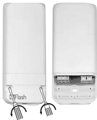
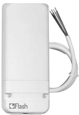
RF receiver installation
① Pushbutton for configuration and override
② Network presence
③ ON/OFF output display
Installation
Coding of transmitter with the receiver
Important : the transmitter + receiver assemblyis factory coded and is therefore immediately
- operationalnal.
There is no need to recode.
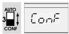
- Set switch 3 at the back of Thermoflash Digi 2 RF to CONF position. The display indicates CONF.
- Press the pushbutton of the receiver for more than 3 seconds. The indicator light OK flickers.
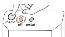
- Press the Thermoflash Digi 2 RF pushbutton for more than 3 seconds.
- The indicator light OK of the receiver stops flickering, showing that the transmission / reception link has been established.
- Return the switch located at the back of the Thermoflash Digi 2 to the AUTO position.
ON/OFF Priority settings
In the event of problem in your installation, the state of the output can be priority set to ON or OFF.
Press shortly the receiver button (less than 3 seconds).
Each short pressing will change the output state.
To reset the receiver
- To remove all transmitter/receiver links:
- Press the receiver's pushbutton for more than 10 sec.
- The OK indicator light flickers slowly then more quickly.
- Press again the receiver's pushbutton for 3 sec.
- The OK indicator light stops flickering and all codes are removed.
The receiver switch back to «auto» mode.
- To remove one single transmitter/receiver link:
- Press the receiver's pushbutton for more than 10 sec.
- The OK indicator light flickers slowly then more quickly.
- Using the decoding transmitter, press the + button of the Thermoflash Digi 2 in CONF mode for 3 sec.
- The OK indicator light stops flickering and this transmitter/receiver link is removed.
The receiver switch back to «auto» mode.
Troubleshooting Guide
The heating system does not start.
- Receiver's power supply is cut off (OK light is off) Check fuse and circuit breaker.
- Receiver is outside of transmitter's range
- Move transmitter closer to receiver.
- Receiver does not recognise transmitter's code
Re-install receiver.
- Receiver is disturbed by radio transmission (radio ham, TV monitor, cellular phone re-transmitter, etc.) Attempt to remove the source of disturbance.
- Transmitter is located in a disturbed area
- Move transmitter out of the disturbed area.
In case of persistent problem, call on your electrician.
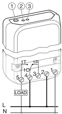
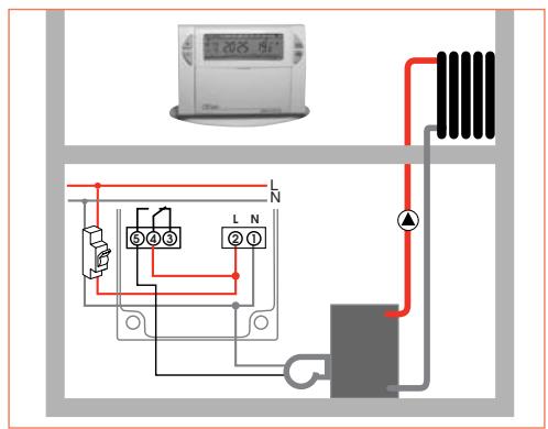
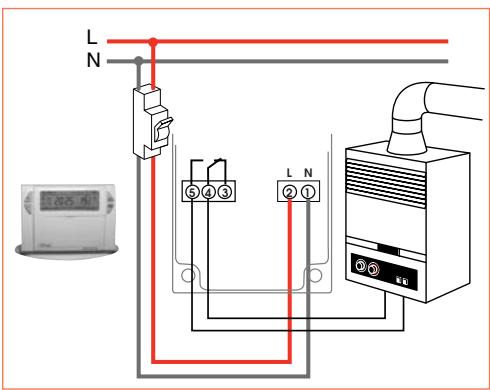
Electrical connection
Before working on the installation, isolate all electrical supplies.
- All electrical wiring must be carried out by a qualified person.
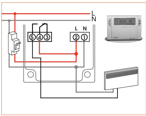
For easier installation, the Thermoflash Digi 2 HF kit is supplied with a flexible 4-wire 1.5mm^2 cable of 1.20m length (not connected).
We recommend using this cable for connecting the HF receiver according to the following colour codes:
Brown = phase
Blue = neutral
Gray
Black
connection to the boiler
Sanfil,))))
Kit THERMOFLASH DIGI 2 HF
Kit THERMOFLASH DIGI 2 HF
Kit Thermoflash DIGI 2 HF Termostato programable sin hilos Ciclo semanal y receptor mural IP43
Receptor Mural IP 43
Receptor mural IP 43.