USER MANUAL MS-7597 MSI
FCC-B RADIO FREQUENCY INTERFERENCE STATEMENT
This equipment has been tested and found to comply with the limits for a class B digital device, pursuant to part 15 of the FCC rules. These limits are designed
to provide reasonable protection against harmful interference in a residential installation. This equipment generates, uses and can


radiate radio frequency energy and, if not installed and used in accordance with the instruction manual, may cause harmful interference to radio communications. However, there is no guarantee that interference will occur in a particular installation. If this equipment does cause harmful interference to radio or television reception, which can be determined by turning the equipment off and on, the user is encouraged to try to correct the interference by one or more of the measures listed below.
Reorient or relocate the receiving antenna.
Increase the separation between the equipment and receiver.
Connect the equipment into an outlet on a circuit different from that to which the receiver is connected.
Consult the dealer or an experienced radio/ television technician for help.
Notice 1
The changes or modifications not expressly approved by the party responsible for compliance could void the user's authority to operate the equipment.
Notice 2
Shielded interface cables and A.C. power cord, if any, must be used in order to comply with the emission limits.
SEE THE INSTALLATION NOTICE BEFORE CONNECTING TO THE NETWORK.

Micro-Star International MS-7597
This device complies with Part 15 of the FCC Rules. Operation is subject to the following two conditions:
(1) this device may not cause harmful interference, and (2) this device must accept any interference received, including interference that may cause undesired operation.
PART NUMBER
G52-75971X6
COPYRIGHT NOTICE
The material in this document is the intellectual property of MICRO-STAR INTERNATIONAL. We take every care in the preparation of this document, but no guarantee is given as to the correctness of its contents. Our products are under continual improvement and we reserve the right to make changes without notice.
TRADEMARKS
All trademarks are the properties of their respective owners.
MSI is registered trademark of Micro-Star Int'l Co., Ltd. NVIDIA® is registered trademark of NVIDIA Corporation. ATI® is registered trademark of ATI Technologies, Inc. AMD is registered trademarks of AMD Corporation. Intel is registered trademarks of Intel Corporation. Windows® is registered trademarks of Microsoft Corporation. AMI® is registered trademark of Advanced Micro Devices, Inc. Award® is a registered trademark of Phoenix Technologies Ltd. Sound Blaster® is registered trademark of Creative Technology Ltd. Realtek® is registered trademark of Realtek Semiconductor Corporation. JMicron® is registered trademark of JMicron Technology Corporation. Netware is a registered trademark of Novell, Inc.
REVISION HISTORY
| Revision | Revision History | Date |
| V1.2 | Add a new model GF615M-P33 | May 2009 |
| V1.3 | For GF615M-P33/ P31 | December 2009 |
| V1.5 | Update JSP1 from V1.3 | July 2010 |
SAFETY INSTRUCTIONS
Always read the safety instructions carefully. - Keep this User Manual for future reference. - Keep this equipment away from humidity. Lay this equipment on a reliable flat surface before setting it up. - The openings on the enclosure are for air convection hence protects the equipment from overheating. Do not cover the openings. - Make sure the voltage of the power source and adjust properly 110/220V before connecting the equipment to the power inlet. - Place the power cord such a way that people can not step on it. Do not place anything over the power cord. Always Unplug the Power Cord before inserting any add-on card or module. All cautions and warnings on the equipment should be noted. - Never pour any liquid into the opening that could damage or cause electrical shock. If any of the following situations arises, get the equipment checked by a service personnel:
The power cord or plug is damaged. Liquid has penetrated into the equipment. The equipment has been exposed to moisture. The equipment does not work well or you can not get it work according to User Manual. The equipment has dropped and damaged. The equipment has obvious sign of breakage.
- Do not leave this equipment in an environment unconditioned, storage temperature above 60°C (140°F), it may damage the equipment.
CAUTION
Danger of explosion if battery is incorrectly replaced. Replace only with the same or equivalent type recommended by the manufacturer.
Warning to users
For better environmental protection, waste batteries should be collected separately for recycling or special disposal.
ENGLISH
To protect the global environment and as an environmentalist, MSI must remind you that...
Under the European Union ("EU") Directive on Waste Electrical and Electronic Equipment, Directive 2002/96/EC, which takes effect on August 13, 2005, products of "electrical and electronic equipment" cannot be discarded as municipal waste anymore and manufacturers of covered electronic equipment will be obligated to take back

such products at the end of their useful life. MSI will comply with the product take back requirements at the end of life of MSI-branded products that are sold into the EU. You can return these products to local collection points.
GERMAN
Thank you for choosing the GF615M-P33/ P31 series (MS-7597 v1.x) Micro-ATX mainboard. The GF615M-P33/ P31 series is designed based on NVIDIA® Geforce 6150SE & nForce 430 chipset for optimal system efficiency. Designed to fit the advanced AMD Phenom™ AM3 processor, the GF615M-P33/ P31 series delivers a high performance and professional desktop platform solution.
Layout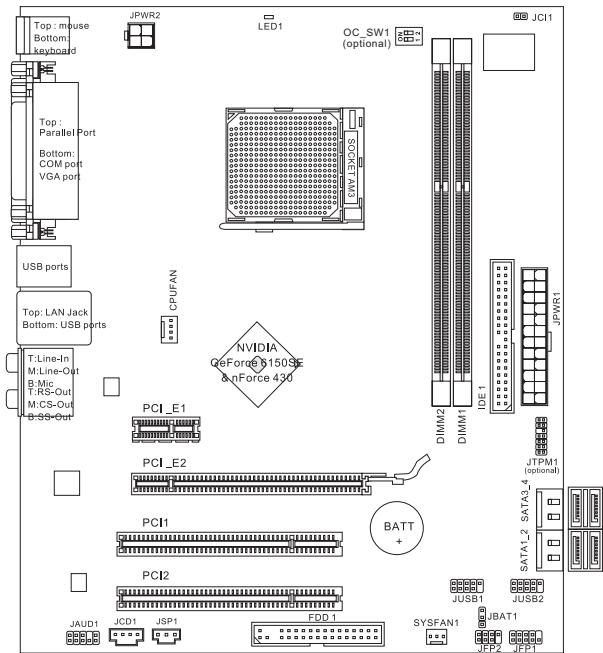
SPECIFICATIONS
Processor Support
Supports AMD Phenom II / Athlon II / Sempron processors in the AM3 package.
(For the latest information about CPU, please visit
http://www.msi.com/index.php?func=cpuform2)
HyperTransport
HyperTransport 1.0
Chipset
NVIDIA® GeForce 6150SE & nForce 430 chipset
Memory Support
DDR3 800/1066/1333 SDRAM (total max. 8GB) 2 DDR3 DIMMs (240-pin/ 1.5V)
(For more information on compatible components, please visit http://www.msi.
com/index.php?func=testreport)
LAN
Supports 10/100/1000 LAN by Realtek® RTL8111DL (GF615M-P33) Or supports 10/100 LAN by Realtek® RTL8103EL (GF615M-P31)
Audio
Chip integrated by Realtek® ALC888S/ ALC889 Supports 7.1 channels audio out Compliant with Azalia 1.0 Spec
IDE
1 IDE port Supports Ultra DMA 66/100/133, PIO & Bus Master operation mode
SATA
4 SATA 3Gb/s ports by NVIDIA® nForce 430
RAID
SATA1~4 support RAID 0/1/5/10
Floppy
1 floppy port Supports 1 FDD with 360 KB, 720 KB, 1.2 MB, 1.44 MB and 2.88 MB
Connectors
Back panel
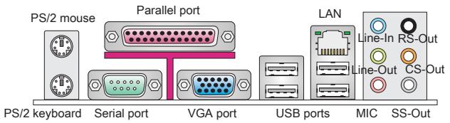
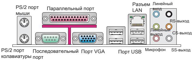
-1PS/2 mouse port - 1 PS/2 keyboard port - 1 COM port - 1 VGA port - 1 parallel port supporting SPP/EPP/ECP mode - 1 LAN jack - 4 USB 2.0 Ports - 6 flexible audio jacks
On-Board Connectors
- 2 USB 2.0 connectors
- 1 SPDIF-Out connector
- 1 Front Panel Audio connector
- 1 CD-In connector
- 1 TPM connector (optional)
- 1 Chassis Intrusion Connector
- 1 Overclock FSB Switch (optional)
Slots
1 PCI Express 1.0 x16 slot, 1 PCI Express 1.0 x1 slot, 2 PCI slots, support 3.3V/5V PCI bus interface
Micro-ATX (24.4cm x 20.0 cm)
Mounting
6 mounting holes
If you need to purchase accessories and request the part numbers, you can search the product web page and find details at our web address below: http://www.msi.com/index.php
REAR PANEL
The rear panel provides the following connectors:
HARDWARE SETUP
This chapter provides you with information about hardware setup procedures. While doing the installation, be careful in holding the components and follow the installation procedures. For some components, if you install them in the wrong orientation, they will not work properly. Use a grounded wrist strap before handling computer components. Static electricity may damage the components.
CPU & Cooler Installation for AM3
When you are installing the CPU, make sure the CPU has a cooler attached on top to prevent overheating. Meanwhile, do not forget to apply some thermal paste on the CPU before installing the heat sink/cooler fan for better heat dispersion.
Follow the steps below to install the CPU & cooler correctly. Wrong installation will cause damage to your CPU and mainboard.
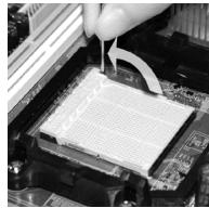
- Pull the lever sideways away from the socket. Make sure to raise the lever up to a 90-degree angle.
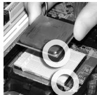
- Look for the gold arrow of the CPU. The gold arrow should point as shown in the picture. The CPU can only fit in the correct orientation.
- If the CPU is correctly installed, the pins should be completely embedded into the socket and can not be seen. Please note that any violation of the correct installation procedures may cause permanent damages to your mainboard.
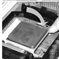
- Press the CPU down firmly into the socket and close the lever. As the CPU is likely to move while the lever is being closed, always close the lever with your fingers pressing tightly on top of the CPU to make sure the CPU is properly and completely embedded into the socket.
- Position the cooling set onto the retention mechanism. Hook one end of the clip to hook first.
- Then press down the other end of the clip to fasten the cooling set on the top of the retention mechanism. Locate the Fix Lever and lift it up.
- Fasten down the lever.
- Attach the CPU Fan cable to the CPU fan connector on the mainboard.
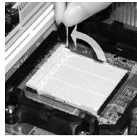
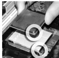
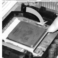
IMPORTANT
- Mainboard photos shown in this section are for demonstration of the cooler installation for Socket AM3 CPUs only. The appearance of your mainboard may vary depending on the model you purchase.
- While disconnecting the Safety Hook from the fixed bolt, it is necessary to keep an eye on your fingers, because once the Safety Hook is disconnected from the fixed bolt, the fixed lever will spring back instantly.
Installing Memory Modules
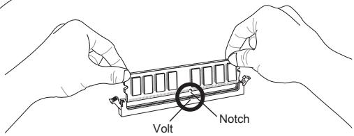
- The memory module has only one notch on the center and will only fit in the right orientation.
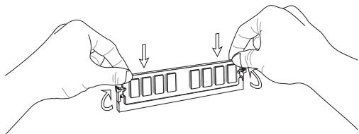
- Insert the memory module vertically into the DIMM slot. Then push it in until the golden finger on the memory module is deeply inserted in the DIMM slot. You can barely see the golden finger if the memory module is properly inserted in the DIMM slot.
- The plastic clip at each side of the DIMM slot will automatically close.
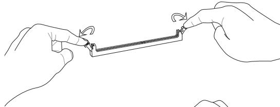
IMPORTANT
- DDR3 memory modules are not interchangeable with DDR2 and the DDR3 standard is not backwards compatible. You should always install DDR3 memory modules in the DDR3 DIMM slots.
- In Dual-Channel mode, make sure that you install memory modules of the same type and density in different channel DIMM slots.
- To enable successful system boot-up, always insert the memory modules into the DIMM1 first.
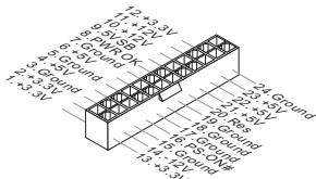
ATX 24-Pin Power Connector: JPWR1
This connector allows you to connect an ATX 24-pin power supply. To connect the ATX 24-pin power supply, make sure the plug of the power supply is inserted in the proper orientation and the pins are aligned. Then push down the power supply firmly into the connector.
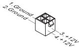
ATX 4-Pin Power Connector: JPWR2
This 12V power connector is used to provide power to the CPU.
IMPORTANT
- Make sure that all the connectors are connected to proper ATX power supplies to ensure stable operation of the mainboard.
- Power supply of 350 watts (and above) is highly recommended for system stability.
Floppy Disk Drive Connector: FDD1
This connector supports 360 KB, 720 KB, 1.2 MB, 1.44 MB or 2.88 MB floppy disk drive.
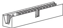
IDE Connector: IDE1
This connector supports IDE hard disk drives, optical disk drives and other IDE devices.
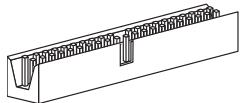
IMPORTANT
If you install two IDE devices on the same cable, you must configure the drives to cable select mode or separately to master / slave mode by setting jumpers. Refer to IDE device documentation supplied by the vendors for jumper setting instructions.
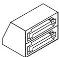
Serial ATA Connector: SATA1 ~ 4
This connector is a high-speed Serial ATA interface port. Each connector can connect to one Serial ATA device.
IMPORTANT
Please do not fold the Serial ATA cable into 90-degree angle. Otherwise, data loss may occur during transmission.
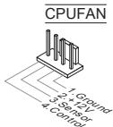
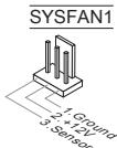
Fan Power Connectors: CPUFAN, SYSFAN1
The fan power connectors support system cooling fan with +12V. When connecting the wire to the connectors, always note that the red wire is the positive and should be connected to the +12V; the black wire is Ground and should be connected to GND. If the mainboard has a System Hardware Monitor chipset onboard, you must use a specially designed fan with speed sensor to take advantage of the CPU fan control.
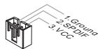
S/PDIF-Out Connector: JSP1
This connector is used to connect S/PDIF (Sony & Philips Digital Interconnect Format) interface for digital audio transmission.
CD-In Connector: JCD1
This connector is provided for external audio input.
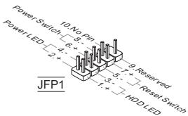
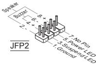
Front Panel Connectors: JFP1, JFP2
These connectors are for electrical connection to the front panel switches and LEDs. The JFP1 is compliant with Intel® Front Panel I/O Connectivity Design Guide.
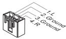
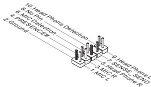
Front Panel Audio Connector: JAUD1
This connector allows you to connect the front panel audio and is compliant with Intel® Front Panel I/O Connectivity Design Guide.
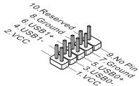
Front USB Connector: JUSB1/ JUSB2
This connector, compliant with Intel® I/O Connectivity Design Guide, is ideal for connecting high-speed USB interface peripherals such as USB HDD, digital cameras, MP3 players, printers, modems and the like.
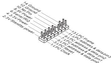
TPM Module connector: JTPM1 (optional)
This connector connects to a TPM (Trusted Platform Module) module. Please refer to the TPM security platform manual for more details and usages.
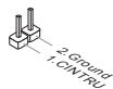
Chassis Intrusion Connector: JCI1
This connector connects to the chassis intrusion switch cable. If the chassis is opened, the chassis intrusion mechanism will be activated. The system will record this status and show a warning message on the screen. To clear the warning, you must enter the BIOS utility and clear the record.
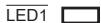
APS LED Status Indicator: LED1
These APS (Active Phase Switching) LEDs indicate the current CPU power phase mode. Follow the instructions below to read.
| ON | The LED will light when CPU is in 3 phase power mode. |
| OFF | The LED off when CPU is in 1 phase power mode. |
Clear CMOS Jumper: JBAT1
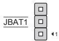
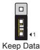
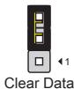
There is a CMOS RAM onboard that has a power supply from an external battery to keep the data of system configuration. With the CMOS RAM, the system can automatically boot OS every time it is turned on. If you want to clear the system configuration, set the jumper to clear data.
IMPORTANT
You can clear CMOS by shorting 2-3 pin while the system is off. Then return to 1-2 pin position. Avoid clearing the CMOS while the system is on; it will damage the mainboard.
Overclock FSB Switch: OC_SW1 (optional)
You can overclock the FSB to increase the processor frequency by changing the switch. Follow the instructions below to set the FSB.
Default
Increase FSB speed by 10%
Increase FSB speed by 15%
Increase FSB speed by 20%
IMPORTANT
- Make sure that you power off the system before setting the switch.
- If overclocking causes system instability or a crash during boot, please set the switch to the default setting.
PCI Express Slot
The PCI Express slot supports PCI Express interface expansion cards.
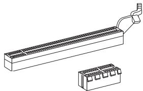
The PCI Express 1.0 x16 slot
The PCI Express 1.0 x1 slot
PCI Slot
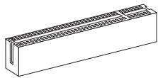
The PCI slot supports LAN cards, SCSI cards, USB cards, and other add-on cards that comply with PCI specifications.
IMPORTANT
Make sure that you unplug the power supply first. Also, read the documentation for the expansion card to configure any necessary hardware or software settings for the expansion card, such as jumpers, switches, or BIOS configuration.
PCI Interrupt Request Routing
When adding or removing expansion cards, make sure that the IRQ (interrupt request line, pronounced I-R-Q) is properly assigned. IRQs are hardware lines over which devices can send interrupt signals to the microprocessor. The PCI IRQ pins are typically connected to the PCI bus pins as follows:
| Order Slot | 1 | 2 | 3 | 4 |
| PCI 1 | C# | D# | A# | B# |
| PCI 2 | B# | C# | D# | A# |
BIOS SETUP
Power on the computer and the system will start the POST (Power On Self Test) process. When the message below appears on the screen, press the key to enter Setup.
Press DEL to enter SETUP
If the message disappears before you respond and you still wish to enter Setup, restart the system by turning it off and on or pressing the RESET button. You may also restart the system by simultaneously pressing the <Ctrl>, <Alt>, and <Delete> keys.
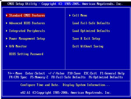
Main Page
Standard CMOS Features
Use this menu for basic system configurations, such as time, date, etc.
Advanced BIOS Features
Use this menu to set up the items of special enhanced features.
Integrated Peripherals
Use this menu to specify your settings for integrated peripherals.
Power Management Setup
Use this menu to specify your settings for power management.
H/W Monitor
This entry shows the status of your CPU, fan, and warning for overall system status.
BIOS Setting Password
Use this menu to set the BIOS setting password.
Use this menu to specify your settings for frequency/voltage control.
Load Fail-Safe Defaults
Use this menu to load the BIOS default values that are factory settings for system operations.
Load Optimized Defaults
Use this menu to load factory default settings into the BIOS for stable system performance operations.
Save & Exit Setup
Save changes to CMOS and exit setup.
Exit Without Saving
Abandon all changes and exit setup.
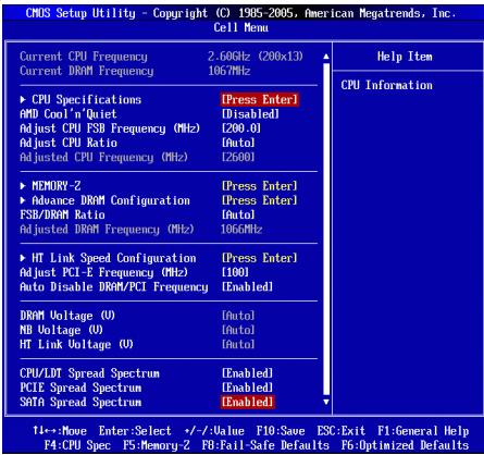
Current CPU/DRAM Frequency
It shows the current frequency of CPU/Memory. Read-only.
CPU Specifications
Press to enter the sub-menu. This submenu shows the information of the installed CPU.
CPU Technology Support
Press to enter the sub-menu. This sub-menu shows the technologies that the installed CPU supports.
AMD Cool'n'Quiet
The Cool'n'Quiet technology can effectively and dynamically lower CPU speed and power consumption.
IMPORTANT
To ensure that the Cool'n'Quiet function is activated and will work properly, it is required to double confirm that:
- Run BIOS Setup, and select Cell Menu. Under Cell Menu, find AMD Cool'n'Quiet, and set this item to "Enabled".
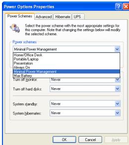
- Enter Windows, and select [Start]->[Settings]->[Control Panel]->[Power Options]. Enter Power Options Properties tab, and select Minimal Power Management under Power schemes.
Adjust CPU FSB Frequency (MHz)
This item allows you to adjust the CPU FSB frequency.
Adjust CPU Ratio
This item is used to adjust CPU clock multiplier (ratio). It is available only when the processor supports this function.
Adjusted CPU Frequency (MHz)
It shows the adjusted CPU frequency (FSB x Ratio). Read-only.
Memory-Z
Press to enter the sub-menu.
Press to enter the sub-menu. This sub-menu displays the information of installed memory.
Advance DRAM Configuration
Press to enter the sub-menu.
DRAM Timing Mode
This field has the capacity to automatically detect the DRAM timing. If you set this field to [DCT 0], [DCT 1] or [Both], some fields will appear and selectable. DCT 0 controls channel A and DCT1 controls channel B.
1T/2T Memory Timing
When the DRAM Timing Mode is set to [Manual], the field is adjustable. This field controls the command rate. Selecting [1T] makes DRAM signal controller to run at 1 clock cycle rate. Selecting [2T] makes DRAM signal controller run at 2 clock cycles rate.
DCT Unganged Mode
This feature is used to Integrate two 64-bit DCTs into a 128-bit interface.
Bank Interleaving
Bank Interleaving is an important parameter for improving overclocking capability of memory. It allows the system to access multiple banks simultaneously.
Power Down Enable
This is a memory power-saving technology. When the system does not access memory over a period of time, it will automatically reduce the memory power supply.
MemClk Tristate C3/ATLVID
This setting allows you to enable/disable the MemClk Tristating during C3 and ATLVID.
FSB/DRAM Ratio
This item will allow you to adjust the ratio of FSB to memory.
Adjusted DRAM Frequency (MHz)
It shows the adjusted memory frequency. Read-only.
HT Link Speed Configuration
Press to enter the sub-menu.
HT Link Speed Auto
Setting to [Enabled], the system will detect the HT link speed automatically.
HT Link Speed
This item allows you to set the Hyper-Transport Link speed.
Adjust PCI-E Frequency (MHz)
This item allows you to adjust the PCI-E frequency.
Auto Disable DRAM/PCI Frequency
When set to [Enabled], the system will remove (turn off) clocks from empty DIMM and PCI slots to minimize the electromagnetic interference (EMI).
DRAM Voltage (V)/ NB Voltage (V)/ HT Link Voltage (V)
These items are used to adjust the voltage of CPU, Memory and chipset.
CPU/LDT Spread Spectrum
This setting is used to enable or disable the CPU/LDT (HT Bus multiplier) Spread Spectrum feature.
PCIE Spread Spectrum
This setting is used to enable or disable the PCIE Spread Spectrum feature.
SATA Spread Spectrum
This setting is used to enable or disable the SATA Spread Spectrum feature.
IMPORTANT
- If you do not have any EMI problem, leave the setting at [Disabled] for optimal system stability and performance. But if you are plagued by EMI, select the value of Spread Spectrum for EMI reduction.
- The greater the Spread Spectrum value is, the greater the EMI is reduced, and the system will become less stable. For the most suitable Spread Spectrum value, please consult your local EMI regulation.
- Remember to disable Spread Spectrum if you are overclocking because even a slight jitter can introduce a temporary boost in clock speed which may just cause your overclocked processor to lock up.
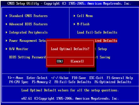
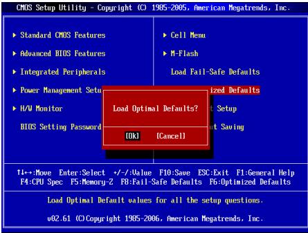
Load Optimized Defaults
You can load the default values provided by the mainboard manufacturer for the stable performance.
Current CPU/DRAM Frequency
CPU Specifications
Adjust CPU FSB Frequency (MHz)
Adjust CPU Ratio
Adjusted CPU Frequency (MHz)
Memory-Z
Advance DRAM Configuration (GoQ DRAM Nx)
Bank Interleaving (Bank Interleaving)
Press DEL to enter SETUP
Advanced BIOS Features
Integrated Peripherals
BIOS Setting Password
Current CPU/DRAM Frequency
CPU Technology Support
Adjust CPU FSB Frequency (MHz)
Adjusted CPU Frequency (MHz)
Adjusted DRAM Frequency (MHz)
Adjust PCI-E Frequency (MHz)
CPU/LDT Spread Spectrum
Press DEL to enter SETUP
Advanced BIOS Features
Integrated Peripherals
BIOS Setting Password
Current CPU/ DRAM Frequency
CPU Technology Support
Adjust CPU FSB Frequency (MHz)
Adjusted CPU Frequency (MHz)
Adjusted DRAM Frequency (MHz)
Adjust PCI-E Frequency (MHz)
CPU/LDT Spread Spectrum
SYSTEM COMPONENTS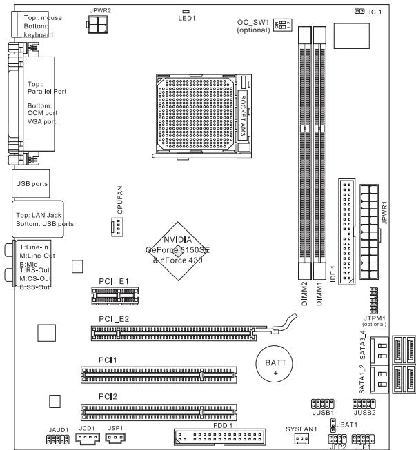
SPECIFICATIONS
Processor
Processors AMD Phenom II / Athlon II / Sempron in AM3 socket. (For more information about CPU, please visit http://www.msi.com/index.php?func=cpuform2)
HyperTransport
HyperTransport 1.0
Unncet
NVIDIA® GeForce 6150SE & nForce 430
PamrTb
DDR3 800/1066/1333 SDRAM (Max. 8GB) 3a cnota DDR3 DIMM (240kOH7 1.5V) (3a dononHnTeBno INHΦoPmaUe n oNpdepeKbAeMbX MoyIpy NocTeTne caHt://www.msi.com/index.php?func=testreport)
LAN
Плобденихka 10/100/1000 LAN на чincete Realtek® RTL8111DL (GF615M-P33) ■Иип подөрхька 10/100 LAN на чинсerte Realtek® RTL8103 (GF615M-P31)
Aydno
INTerpnpoBaHHbYuNCeT Realtek ALC888S/ALC889 Aydno 7.1 c rnbkm npeha3naeHne pa3bemOB CoBmecTnMoCTb co cneunfkaunei Azalia 1.0
IDE
1 nopT IDE Подэржka рекимов pa60ы Ultra DMA 66/100/133, PIO& Bus Master
SATA
4 nopTa SATA 3Gb/s noDpeKmbaOT 4 npBIOOB SATA 3Gb/s
RAID
SATA1~4 noDnepKnBaIoT peKmbl RAID 0/1/5/10
Φnonnn
1ФJIOONnnoT Подержka 1 FDD c 360Kb, 720Kb, 1.2Mb, 1.44Mb u 2.88Mb
KoHHeKTopbl
3aDne nanei
-1PS/2npTMbIu -1PS/2npTknabnAtypb - 1 nopT COM - 1 nopT VGA - 1 napannelbHbI nopT noDepxNBAeT pexmbl SPP/EPP/ECP - 1 pa3beM LAN - 4 nopTa USB 2.0 -63ByKOBbIX pa3beMOB Cn6KIM NpeHa3NaeHHeM
Pa3bembl,yctahOBnEHhIeHa nNaTe
- 2 pa3bema USB 2.0
- 1 pa3bem SPDIF-Out
- 1 pa3bem dny noDKnOyeHna ydyno Ha nepeDne naHeN
- 1 pa3bem CD-In
- 1 pa3bem TPM (onuohalbo)
- 1 pa3bem DaTcNka OTKpbBaHnna Kopnyca
- 1 nepeknquateen annapathoro pa3roha FSB (onuohalbho)
CnotbI
1x PCI Express 1.0 x16 1x PCI Express 1.0 x1 2x PCI, support PCI interface with 3.3V/5V power
Form Factor
Micro-ATX (24.4cm x 20.0cm)
Mounting
Mounting holes
If you need to purchase accessories or find out the part number of your product, this information can be found on the website at http://www.msi.com/index.php
Rear Panel
The rear panel provides the following connectors:
Hardware Setup
This chapter is dedicated to the installation of the processor, memory modules, and expansion cards, as well as setting the jumpers. It also describes how to connect peripheral devices, such as the mouse, keyboard, etc. When installing hardware, be careful and follow the installation instructions.
Installing the CPU and Cooler for AM3
To prevent overheating during operation, install the CPU cooler. Also, to improve heat dissipation, make sure that the thermal paste is applied on the processor before installing the cooler.
Follow the instructions below for proper installation. Incorrect installation may damage the processor and the system board.
1. Lift the lever to the vertical position, and then remove the socket cover. 2. Pay attention to the gold arrow on the CPU. It should be positioned as shown in the figure. The CPU can only be inserted in the correct orientation. 3. When the CPU is correctly installed, its contacts will fit into the socket without force. Do not apply excessive force during installation, as it may cause serious damage to the system board. 4. Gently press the CPU into the socket and close the lever. Since the CPU may shift during installation, carefully press it down and ensure it is properly and securely fixed. 5. Place the cooler on the mounting bracket, aligning one of its edges. 6. Then press the other edge to install the cooler onto the mounting bracket. Start the clip and then lift it. 7. Secure the cooler by turning the lever.
- Connect the CPU cooler cable to the corresponding connector on the system board.
* The system board layout shown in this section is for demonstration purposes only, for installing the processor into the Socket AM3 CPU. The actual layout may differ from what is shown here. * When releasing the locking lever, be careful, as the lever is spring-loaded and will snap back to the closed position.
Installing the memory module
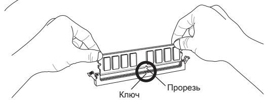
- Memory modules have only one notch in the center. Module insertion 1.
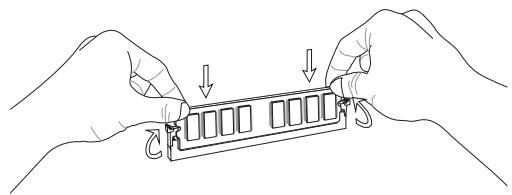
- Insert the module in a vertical direction. Then press down on it so that the retaining clips snap deeply into the DIMM slot. The contacts should be fully inserted if the memory module is correctly placed in the DIMM slot. 3. When the module is fully inserted, the locking clips on both sides of the slot will close automatically.

CAUTION
- DDR3 modules are not interchangeable with DDR2 modules, and the DDR3 standard is not backward compatible. The DDR3 memory module should only be installed in a DDR3 slot. To work in dual-channel mode, make sure that the memory modules of the same type and capacity are installed in the same color slots. * To ensure the system boots, first install the module in the DIMM1 slot.
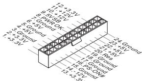
24-pin ATX power connector: JPWR1
This connector allows you to connect a 24-pin ATX power supply to the motherboard. Before connecting, make sure that all the plugs from the power supply are properly aligned and correctly centered. Gently insert it into the connector on the system board.
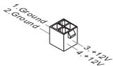
ATX 4-pin power connector: JPWR2
This 12V power connector is used to provide power to the processor.
CAUTION
- Make sure that all connectors are properly connected. It is recommended to use a power supply of 350W (or higher) for stable system operation.
FDD connector: FDD1
This connector supports floppy disk drives with capacities of 360KB, 720KB, 1.2MB, 1.44MB, and 2.88MB.
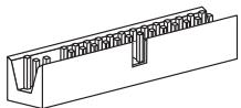
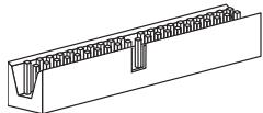
IDE1 connector
The IDE connector supports IDE hard disks, optical disks, and other IDE devices.
WARNING
When connecting two devices to one cable, you must set the devices to master/slave mode using the jumpers. For instructions, refer to the device manufacturer's documentation.
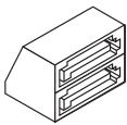
Serial ATA connectors: SATA1 ~ 4
The Serial ATA connector is a high-speed interface for Serial ATA devices. This connector allows you to connect only one Serial ATA device.
WARNING
Avoid sharp bends in the Serial ATA cable. Otherwise, data loss may occur during transmission.
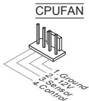
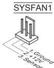
Fan connectors: CPUFAN, SYSFAN1
The fan connectors support fans with a 12V power supply. When connecting, remember that the red wire goes to +12V and the black wire to ground (GND). If the system board contains a fan speed monitoring chip, you must use special fans with a speed sensor to utilize the fan control function.
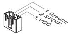
S/PDIF-Out connector: JSP1
This connector is used to connect the S/PDIF (Sony & Philips Digital Interconnect Format) interface for digital audio output.
CD-In connector: JCD1
This connector is designed for connecting an additional audio cable.
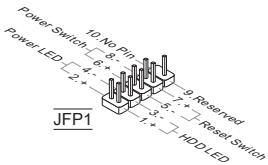
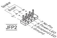
Front panel connectors: JFP1, JFP2
The front panel headers provide connection for the front panel indicators and buttons. JFP1 complies with the Intel® Front Panel I/O Connectivity Design Guide.
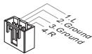
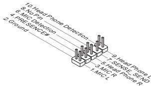
Front panel audio header: JAUD1
This header allows you to connect audio to the front panel. It complies with the Intel Front Panel I/O Connectivity Design Guide.
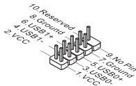
Front panel USB headers: JUSB1/JUSB2
These headers, which are compatible with the Intel I/O Connectivity Design Guide, provide connection for high-speed peripherals such as USB HDDs, digital cameras, MP3 players, printers, modems, etc.
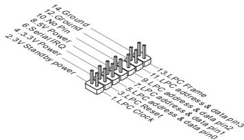
TPM header: JTPM1 (optional)
This header is designed for connecting a TPM (Trusted Platform Module) module. For more information on the possibilities of using the TPM security platform, please refer to the TPM security platform guide.
Chassis intrusion detection header: JCI1
The chassis intrusion detection cable, installed in the chassis, connects to this connector. When the chassis is opened, its mechanism is activated. The system records the event and issues a warning on the screen. The warning can be disabled in the BIOS settings.
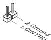
Status indicator: LED1 (optional)
These APS (Active Phase Switching) LEDs indicate the operating mode of the processor power supply. Information on the status of the LEDs is given in the table.

Main Page (Main Menu)
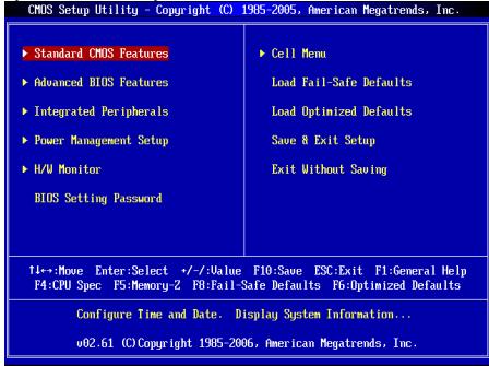
Standard CMOS Features
This menu allows you to set the basic parameters of the system configuration (date, time, etc.)
Advanced BIOS Features
This menu is used to configure special BIOS functions.
Integrated Peripherals
This menu is used to configure the parameters of the integrated peripherals.
Power Management Setup
This menu allows you to set the power management parameters of the system.
H/W Monitor
This item displays the status of the hardware part of the PC.
BIOS Setting Password
This menu is used to set the password.
This menu allows you to control the clock frequencies and voltages during overclocking.
Load Fail-Safe Defaults
This menu is used to load the BIOS values set by the manufacturer for stable system operation.
Load Optimized Defaults
This menu is used to set the settings for optimal performance and stability of the system board.
Save & Exit Setup (Save settings and exit)
Save changes to CMOS and exit setup mode.
Exit Without Saving (Exit without saving)
Cancel all changes and exit setup mode.
Cell Menu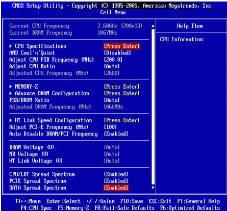
Current CPU/DRAM Frequency
This item shows the current CPU frequency and memory speed. For reference only.
CPU Specifications
Press <Enter> to enter the submenu, which shows information about the installed CPU.
CPU Technology Support
Press <Enter> to enter the submenu, which shows the technologies supported by the installed CPU.
AMD Cool'n'Quiet
The Cool'n'Quiet technology allows the system to dynamically change the CPU frequency and power consumption.
NOTE
To ensure that the Cool'n'Quiet technology works correctly, it is necessary to:
- Set the AMD Cool'n'Quiet option in the BIOS Setup, in the Cell Menu. If you cannot find AMD Cool'n'Quiet in the Cell Menu, set it to "Enabled".
- In Windows, select [Start]->[Settings]->[Control Panel]->[Power Options]. In Power Options Properties, select Minimal Power Management in Power schemes.
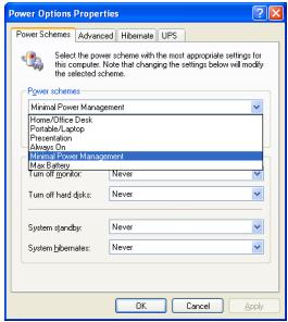
Adjust CPU FSB Frequency (MHz)
This item allows you to select the FSB frequency of the processor.
Adjust CPU Ratio
This item is used to adjust the multiplier of the processor. It is available only when the processor supports this function.
Adjusted CPU Frequency (MHz)
This item displays the current CPU frequency (FSB x Ratio). It is for reference only.
Memory-Z
Press Enter to enter the submenu.
Press Enter to enter the submenu. This item displays the information about the installed memory modules.
Advance DRAM Configuration
Press Enter to enter the submenu.
DRAM Timing Mode
These items automatically determine the DRAM timing parameters. When setting [DCT 0], [DCT 1], or [Both], some items become accessible. DCT 0 controls channel A, and DCT 1 controls channel B.
1T/2T Memory Timing
When DRAM Timing Mode is set to [Manual], this item becomes accessible. This item determines the speed of DRAM commands. Selecting [1T] sets the SDRAM signal control to 1T operation (T = clock cycle). Selecting [2T] sets the SDRAM signal control to 2T operation.
DCT Unganged Mode
This item is used to combine two 64-bit DCTs into one 128-bit interface.
Bank Interleaving
Bank Interleaving is an important parameter that affects memory performance. Enabling it allows access to multiple memory banks simultaneously.
Power Down Enable
This item controls the power-saving technology. When there is no access to memory for a certain period, the system automatically reduces power to the memory.
MemClk Tristate C3/ATLVID
This item allows enabling or disabling the three-state operation mode during C3 and ATLVID.
FSB/DRAM Ratio
This item allows adjusting the FSB and DRAM frequency.
Adjusted DRAM Frequency (MHz)
This item shows the actual memory frequency. For reference only.
HT Link Speed Configuration
This item allows you to enter the submenu.
HT Link Speed Auto
When set to [Enabled], the system will automatically determine the HT Link speed.
HT Link Speed
This item allows you to set the transfer speed of the HyperTransport link.
Adjust PCI-E Frequency (MHz)
This item allows you to set the PCIE frequency.
Auto Disable DRAM/PCI Frequency
When set to [Enabled], the system will disable unused PCI slots, which will reduce the level of electromagnetic interference (EMI).
DRAM Voltage (V)/ NB Voltage (V)/ HT Link Voltage (V)
This item allows you to adjust the voltage of the CPU, memory, and chipset.
CPU/LDT Spread Spectrum
This item is used to enable/disable the CPU/LDT (HT Bus multiplier) Spread Spectrum technology.
PCIE Spread Spectrum
This item allows you to enable or disable the PCIE Spread Spectrum feature.
SATA Spread Spectrum
This item allows you to enable or disable the SATA Spread Spectrum feature.
IMPORTANT
If you do not have any interference problems, leave the value at [Disabled] for better stability and performance. However, if you encounter electromagnetic interference, select Spread Spectrum to reduce it. * The higher the Spread Spectrum value, the lower the level of electromagnetic interference, but the system will become less stable. To choose the appropriate Spread Spectrum value, refer to the level of electromagnetic interference set by legislation. Do not forget to disable the Spread Spectrum function if you are overclocking the system. This is necessary because even a slight jitter of the clock generator signals can cause the overclocked processor to fail.
Setting Default Values
To clear all system settings, you can load the default values set by the motherboard manufacturer.
Simplified Chinese
Introduction
Press DEL to enter SETUP
(Press DEL to enter SETUP)
CPU Specifications
CPU/LDT Spread Spectrum
Hardware Overclocking FSB Switch: OC_SW1 (optional)
Press DEL to enter SETUP
(Press DEL to enter SETUP)
Integrated Peripherals
Use this menu to configure integrated peripheral devices.
Adjust CPU FSB Frequency (MHz)
Adjusted CPU Frequency (MHz)
Press DEL to enter SETUP
(Press DEL to enter SETUP)
CMOS Setup Utility - Copyright (C) 1985-2005, American Megatrends, Inc.
Standard CMOS Features Advanced BIOS Features Integrated Peripherals Power Management Setup H/W Monitor
BIOS Setting Password
Cell Menu
Load Fail-Safe Defaults
Load Optimized Defaults
Save & Exit Setup
Exit Without Saving
↑ ↓ ↔ Move Enter:Select +/-Value F10:Save ESC:Exit F1:General Help
F4:CPU Spec F5:Memory-2 F8:Fail-Safe Defaults F6:Optimized Defaults
Configure Time and Date. Display System Information...
002.61 (C) Copyright 1985-2006, American Megatrends, Inc.
CPU Technology Support (CPUtekNoJ-safo-1)
CPU/LDT Spread Spectrum
Enable/Disable CPU/LDT (HT Bus multiplier) Spread Spectrum feature.
PCIE Spread Spectrum