
DN-X900 - DJ Mixer DENON - Free user manual and instructions
Find the device manual for free DN-X900 DENON in PDF.
| Product Type | DJ Mixer |
| Brand | DENON |
| Model | DN-X900 |
| Dimensions | 482 x 112.5 x 177 mm (without feet) |
| Weight | 5.9 kg |
| Power Supply | 230 V AC ±10%, 50 Hz (European model) |
| Power Consumption | 33 W |
| Rack Mounting | 4U, 19 inches |
| Analog Inputs | 8 line (RCA), 3 phono (RCA, switchable line), 2 mic (1 combo XLR/TRS, 1 TRS) |
| Digital Inputs | 4 coaxial (SPDIF, 32-48 kHz, 24 bits) |
| Analog Outputs | Master XLR balanced + RCA, Booth XLR balanced, Zone TRS balanced, Rec RCA, Subwoofer/Lighting TRS, Headphones TRS 1/4" |
| Digital Outputs | 1 coaxial (SPDIF, 20 bits), 1 optical (SPDIF, 20 bits) |
| Channel EQ | 3 bands: Low (60 Hz, +6/-35 dB), Mid (1 kHz, +10/-35 dB), Hi (16 kHz, +10/-35 dB) |
| Microphone EQ | 3 bands: Low (100 Hz), Mid (1 kHz), Hi (10 kHz), range ±12 dB |
| Crossfader | Assignable A/B, adjustable contour, Flex Fader (adjustable glide force) |
| Fader Start | Compatible with DENON CD players (3.5 mm mini-jack) |
| Main Functions | Matrix input assignment, attenuable Talk Over, effect loop, Split Cue, independent zone output |
| Maintenance and Cleaning | Clean with a dry, soft cloth. Do not use solvents or abrasives. |
| Safety | Do not expose to water or humidity. Do not obstruct ventilation openings. Disconnect by pulling the plug. |
| Spare Parts and Repairability | Crossfader and channel faders replaceable (optional parts). |
Frequently Asked Questions - DN-X900 DENON
User questions about DN-X900 DENON
0 question about this device. Answer the ones you know or ask your own.
Ask a new question about this device
Download the instructions for your DJ Mixer in PDF format for free! Find your manual DN-X900 - DENON and take your electronic device back in hand. On this page are published all the documents necessary for the use of your device. DN-X900 by DENON.
USER MANUAL DN-X900 DENON
- TO PREVENT FIRE OR SHOCK HAZARD, DO NOT USE THIS PLUG WITH AN EXTENSION CORD, RECEPTACLE OR OTHEROUTLET ULESS THE BLADES CAN BE FULLY INSERTED TO PRESENT BLADE EXPOSURE.
- TO PREVENT FIRE OR SHOCK HAZARD. DO NOT EXPOSE THIS APPLIANCE TO RAIN OR MOISTURE.
- TO PREVENT ELECTRICAL SHOCK, MATCH WIDE BLADE PLUG TO WIDE SLOT FULLY INSERT.

The lightning flash with arrowhead symbol, within an equilateral triangle, is intended to alert the user to the presence of uninsulated "dangerous voltage" within the product's enclosure that may be of sufficient magnitude to constitute a risk of electric shock to persons.
CAUTION
RISK OF ELECTRIC SHOCK DO NOT OPEN
Warning: To reduce the risk of electric shock, do not remove cover (or back). no user serviceable parts inside. refer servicing to qualified service personnel.

The exclamation point within an equilateral triangle is intended to alert the user to the presence of important operating and maintenance (servicing) instructions in the literature accompanying the appliance.
IMPORTANT SAFETY INSTRUCTIONS
1) Read these instructions.
2) Keep these instructions.
3) Heed all warnings.
4) Follow all instructions.
5) Do not use this apparatus near water.
6) Clean only with dry cloth.
7) Do not block any ventilation openings. Install in accordance with the manufacturer's instructions.
8) Do not install near any heat sources such as radiators, heat registers, stoves, or other apparatus (including amplifiers) that produce heat.
9) Do not defeat the safety purpose of the polarized or grounding-type plug. A polarized plug has two blades with one wider than the other. A grounding type plug has two blades and a third grounding prong. The wide blade or the third prong are provided for your safety. If the provided plug does not fit into your outlet, consult an electrician for replacement of the obsolete outlet.
10) Protect the power cord from being walked on or pinched particularly at plugs, convenience receptacles, and the point where they exit from the apparatus.
11) Only use attachments/accessories specified by the manufacturer.
12) Use only with the cart, stand, tripod, bracket, or table specified by the manufacturer, or sold with the apparatus. When a cart is used, use caution when moving the cart/apparatus combination to avoid injury from tip-over.

13) Unplug this apparatus during lightning storms or when unused for long periods of time.
14) Refer all servicing to qualified service personnel. Servicing is required when the apparatus has been damaged in any way, such as power-supply cord or plug is damaged, liquid has been spilled or objects have fallen into the apparatus, the apparatus has been exposed to rain or moisture, does not operate normally, or has been dropped.
15) This appliance shall not be exposed to dripping or splashing water and that no object filled with liquids such as vases shall be placed on apparatus.
CAUTION:
1. Handle the power supply cord carefully
Do not damage or deform the power supply cord. If it is damaged or deformed, it may cause electric shock or malfunction when used. When removing from wall outlet, be sure to remove by holding the plug attachment and not by pulling the cord.
2. Do not open the top cover
In order to prevent electric shock, do not open the top cover.
If problems occur, contact your DENON dealer.
3. Do not place anything inside
Do not place metal objects or spill liquid inside the DJ mixer.
Electric shock or malfunction may result.
Please, record and retain the Model name and serial number of your set shown on the rating label.
Model name DN-X-500
Serial No.
Model name DN-X-900
Serial No.
FCC INFORMATION (For US customers)
1.PRODUCT
This product complies with Part 15 of the FCC Rules. Operation is subject to the following two conditions: (1) this product may not cause harmful interference, and (2) this product must accept any interference received, including interference that may cause undesired operation.
2. IMPORTANT NOTICE: DO NOT MODIFY THIS PRODUCT
This product, when installed as indicated in the instructions contained in this manual, meets FCC requirements. Modification not expressly approved by DENON may void your authority, granted by the FCC, to use the product.
3. NOTE
This product has been tested and found to comply with the limits for a Class B digital device, pursuant to Part 15 of the FCC Rules. These limits are designed to provide reasonable protection against harmful interference in a residential installation.
This product generates, uses and can radiate radio frequency energy and, if not installed and used in accordance with the instructions, may cause harmful interference to radio communications. However, there is no guarantee that interference will not occur in a particular installation. If this product does cause harmful interference to radio or television reception, which can be determined by turning the product OFF and ON, the user is encouraged to try to correct the interference by one or more of the following measures:
- Reorient or relocate the receiving antenna.
- Increase the separation between the equipment and receiver.
- Connect the product into an outlet on a circuit different from that to which the receiver is connected.
-
Consult the local retailer authorized to distribute this type of product or an experienced radio/TV technician for help.
-
DECLARATION OF CONFORMITY
We declare under our sole responsibility that this product, to which this declaration relates, is in conformity with the following standards: EN60065, EN55013, EN55020, EN61000-3-2 and EN61000-3-3. Following the provisions of 73/23/EEC, 89/336/EEC and 93/68/EEC Directive.
A NOTE ABOUT RECYCLING:
This product's packaging materials are recyclable and can be reused. Please dispose of any materials in accordance with the local recycling regulations.
When discarding the unit, comply with local rules or regulations.
Batteries should never be thrown away or incinerated but disposed of in accordance with the local regulations concerning chemical waste.
This product and the accessories packed together constitute the applicable product according to the WEEE directive except batteries.


HINWEIS ZUM RECYCLING:
Allow for sufficient heat dispersion when installed in a rack.
- Handle the power cord carefully.
Hold the plug when unplugging the cord.
- Minimum distances around the apparatus for sufficient ventilation.
- The ventilation should not be impeded by covering the ventilation openings with items, such as newspapers, table-cloths, curtains, etc..
- No naked flame sources, such as lighted candles, should be placed on the apparatus.
- Attention should be drawn to the environmental aspects of battery disposal.
- The use of apparatus in tropical and/or moderate climates.
ACHTUNG:
1 Main features 1
2 Installation 1
Part names and functions 1,2
4 Connections. 3, 4
Fader start 5
6 Replacing the crossfader. 6
7 Replacing the channelfader. 6
8 Only DN-X900 : FLEX FADER Crossfader slide torque adjustment procedure .6
9 Specifications 7
- ACCESSORIES
Please check to make sure the following items are included with the main unit in the carton:
① Operating instructions 1
② Connection cords (3.5 mm stereo mini cord) 2
③ Audio cord 2
1 MAIN FEATURES
CONGRATULATIONS! You have purchased the DENON DN-X500/DN-X900 DJ mixer from D&M HOLDINGS Inc.
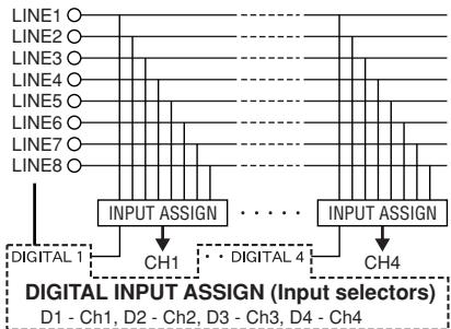
1. Matrix input assignment
8 input sources are freely assignable to each channel.
Only DN-X900: 8 input sources +4 DIGITAL sources are freely assignable to each channel.
2. 60 MM Channel Fader (Replaceable)
60mm long-stroke channel fader for precise adjustment of the volume. Can be replaced with a rotary type (optional).
3. Level Mater per Channel
Easily visible 12- dot level meters for each channel.
4. Booth Assign
1 ch - 4 ch and master Selects the source of the BOOTH output.
5. Enhanced SEND/RETURN terminals
DN-X500:8 LINE,2 PHONO,2 Microphone systems, 2MASTER outputs,BOOTH output and REC output are provided independently.
Effect SEND/RETURN terminals are also provided for an external effects processor.
DN-X900:8 LINE,3 PHONO,4 DIGITAL 2 Microphone systems,2 MASTER outputs,BOOTH output,ZONE output and REC output are provided independently.
Effect SEND/RETURN terminals are also provided for an external effects processor.
6. 3-Band equalizer/gain
LOW, MID, HI and GAIN controls are available on every input channel.
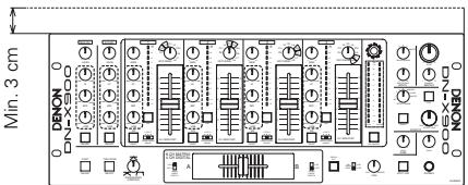
2 INSTALLATION
When the DN-X500/DN-X900 is mounted inside a coffin or DJ booth, we recommend leaving a 3 cm blank space above the mixer if possible.
7. Crossfader Contour
This feature allows adjusting the "shape" of the Crossfader response from a gentle curve for smooth, long running fades, to the steep pitch required for top performance cut and scratch effects.
8. Channel Fader and Crossfader Start
The CD player can be started or stopped simply by increasing or decreasing the level of the Ch. Fader or by using the Crossfader left to right or right to left. (This function can only be used when the DENON CD players DN-D4500 or etc. is connected to the DN-X500 or DN-X900)
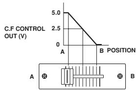
9. Crossfader Control Output
The crossfader adjustment is output to control external equipment.
(In the future, an external effector will be controlled.)
10. Mic Post (Att Level adjusted)
This feature will pass the Mic signal into the BOOTH, ZONE,REC output and DIGITAL output signal path. In the OFF mode, the Mic signal will not be routed through the above outputs.
The Talk Over attenuation Level can be adjusted (- -20dB)
11. Hi-Grade Type Op Amp
The input/output section uses a hi-grade type op amp for high sound quality.
12. Only DN-X900 : Digital Input/Output
Digital Input (Coaxial x X4 : IEC958 Type III 32 kHz-48 kHz 24 bit)
Digital Output (Coaxial x X1 / Optical X1 IEC958 Type II20 bit)
13. Only DN-X900 : FLEX FADER (Adjustable Slide Torque Crossfader.)
The crossfader's slide torque can be adjusted to achieved the desired feeling.
PART NAMES AND FUNCTIONS
(1) Front Panel
MIC EQ controls
- Contour the frequency response of the Mic input -12 dB to +12 dB.
HI
- Adjusts high-tone Mic sound -12dB to +12dB . At the center position, sound is flat.
MID
- Adjusts mid-tone Mic sound -12 dB to +12 dB. At the center position, sound is flat.
LOW
- Adjusts low-tone Mic sound -12dB to +12dB . At the center position, sound is flat.
2 MAIN MIC level control
- Adjusts the level of the Main Mic input.
3 MAIN MIC ON/OFF button
- When the button is lit, Main Mic signal is transferred to output section, otherwise Main Mic input is muted.
MIC POST ON/OFF button
- Puts the MAIN/AUX Mic signal into the Booth and Rec.
Only DN-X900 : Puts the MAIN/AUX Mic signal into the Booth, Zone, Rec and Digital out signal path.
5 AUX MIC level control
- Adjusts the level of the Aux Mic input.
6 AUX MIC ON/OFF button
- When the button is lit, Aux Mic signal is transferred to output section, otherwise Aux Mic input is muted.
TALK OVER ON/OFF button
- Use this to switch the Talk Over function ON and OFF. (ON/OFF is cyclic)
- When the button is lit, level of signals except Mics is attenuated.
- The Talk Over attenuation level adjusts. See below 52
Source EQ controls
- Use VRs with center detent for equaliser.
HI
MID
- Adjusts the high-tone sound -35dB to +10dB . At the center position, sound is flat.
- Adjusts the mid-tone sound -35dB to +10dB . At the center position, sound is flat.
LOW
- Adjusts the low-tone sound -35dB to +6dB . At the center position, sound is flat.
9 EQ ON/ OFF buttons
- When this is lit EQ is on, otherwise EQ is bypassed.
10 GAIN level control
- Adjusts the level of the selected input - to +15 dB.
CH LEVEL meter
- Displays the input level after adjusted with GAIN 10 and EQ 8 controls.
12 SOURCE INPUT ASSIGN (Input selectors)
- Select any source from eight inputs (PHONO1/LINE1, LINE2, PHONO2/LINE3, LINE4, PHONO3/LINE5, LINE6, LINE7, LINE8) for each channel independently. (PHONO3: Only DN-X900)
- You also can assign the same input to several channels for creative mixing.
Only DN-X900
15 Source input fader (Ch. fader)
Controls the level of the selected Input.
14 BOOTH level control
- Adjusts the level of the Booth outputs.
15 BOOTH ASSIGN switch
- Selects the source of the BOOTH output.
16 MASTER LEVEL control
- Adjusts the level of the MASTER outputs
17 MASTER BALANCE control
- Adjusts the L/R balance of the MASTER output.
18 Peak dB CUE/PROGRAM meter
- Displays the output level following Master Level adjustment, the peak level is held for 1 second. Display range: -15 dB to +12 dB.
- Can switch between two display modes. See below 24, 25.
19 EFFECT LOOP ON/OFF button
- Routes the assigned signal through the external processor attached to the SEND/RETURN connectors on the rear.
- When the EFFECT is ON, the button is lit.
- The effect button is flashing when there is no connection of the effects.
20 EFFECT LOOP WET/DRY control
- Use this to adjust the ratio of original and effected sound.
21 EFFECT LOOP ASSIGN switch
- Use this to select the source of the external processor.
22 HEADPHONE output jack
- Accepts 1/4'' stereo headphone plugs.
HEADPHONE level control
- Adjusts the volume for the headphones.
24 SPLIT CUE button
- In the STEREO mode, this button feeds STEREO Program (CUE MASTER) and Cue to both earcups, in the SPLIT CUE (MONO) mode, the headphone circuit provides MONO Cue to the left ear and MONO Program (MASTER) to the right.
- In the STEREO mode, the meter indicates the stereo level in the LEFT and RIGHT Master Outputs. In the SPLIT CUE (MONO) mode, mono Cue level is displayed on the Left meter and mono Program (CUE MASTER) level is displayed on the Right meter.
- In the SPLIT CUE (MONO) mode, the button is lit.
HEADPHONE PAN control
- Serves two purposes... In the STEREO mode it changes the relative levels of the Cue and Program mixed together in both ear cups. In the MONO mode it changes the balance between the Mono Cue in the left ear cup and the Mono Program in the right.
26 CUE buttons
- Pressing in any or all of CUE buttons routes the respective source to the headphone and meter cue sections. Pressing multiple buttons makes it possible to derive mixed sound from the selected sources.
CROSSFADER ASSIGN switch
A, B:
- The channel source is assigned to A or B of the Crossfader.
POST: - Select when you don't assign the channel source into the Crossfader.
28 CROSSFADER
Controls the relative output level from the summed A and B Mixes. When the fader is at its far left, only the A Mix is heard from the Outputs. As the fader is moved toward the right, the amount of B Mix is increased and the amount of A Mix is decreased. When the fader is centered, equal amounts of A and B Mixes are routed to the Outputs. Fully right is all B Mix at the Outputs.
LINE 2,4,6,8 FADER output jacks (Rear Panel
3.5 ~mm stereo mini jack Others should not be affected a terminal short-circuit.
X-CONTROL
In the future, an external effector will be controlled.
X-CONTROL Voltage output jack (Rear Panel 59)
Tip: CROSSFADER CONTROL Voltage Sleeve : GND
23 CROSSFADER CONTOUR control
- Allows adjusting the "shape" of the Crossfader response from a gentle curve for smooth, long running fades, to the steep pitch required for top performance cut and scratch effects.
FADER START
50 POWER indicator
- When the blue indicator is lit, the DN-X500/DN-X900 is ready to go.
31 CROSSFADER START A, B switches
- Use this to switch the Crossfader Start suction ON and OFF.
CH. FADER START switches
- This function will start the performance of CD player with Ch. Fader automatically is on/off.
If the separately sold DN-S3500, DN-D4500 and etc. players are connected to LINE2, 4, 6 or 8, they can be started using the source input fader (Ch. Fader) or Crossfader, as long as the 3.5mm stereo mini cords have been connected.
38 Only DN-X900:TRACK MARK (DIGITAL OUT) button
- The track number is switched when this button is pressed during recording onto a digital recorder using the digital outputs.
34 Only DN-X900 : ZONE level control
- Adjusts the level of the ZONE outputs.
(2) Rear Panel
55 POWER switch
- Press the switch to turn the power on.
36 MAIN OUT (BALANCED) connectors
- These XLR type connectors provide a balanced line level output.
- Connect these connectors to the balanced analog input connectors on an amplifier or console.
Pin layout: 1. Common, 2. Hot, 3. Cold
Applicable connector: Cannon XLR-3-31 or equivalent.
MAIN OUT (UNBALANCED) jacks
- This stereo pair of RCA jacks provides a unbalanced line level output.
- Connect these jacks to the unbalanced analog input jacks on an amplifier or console.
33 BOOTH OUT (BALANCED) connectors
- These XLR type connectors provide a balanced line level output with independent front panel Zone Level controls and are not affected by the Master Level control.
- Connect these connectors to the balanced analog input connectors on an amplifier or console.
- Pin layout: Tip: Hot, Ring: Cold, Sleeve: GND (DN-X500)
Pin layout: 1. Common, 2. Hot, 3. Cold (DN-X900) - Applicable connector: Cannon XLR-3-31 or equivalent.
SUBWOOFER/LIGHTING output jack
- This 1/4'' jacks provide a mono line level output of Main Out. The signal is affected by the Master Level fader.
- Connect these jacks to the subwoofer/Lighting input jack on an amplifier.
40 SUBWOOFER/LIGHTING frequency control
- Adjusts the cut off frequency of the low pass filter 40 Hz to 200 Hz.
- The low adjustment, will affect the Subwoofer/Lighting output.
41 REC OUT jacks
- This stereo pair of RCA jacks provides a line level output. The signal is unaffected by the Master Level control.
- It is intended for use with a tape recorder, but is not restricted to that purpose.
SEND/RETURN jacks
These 1/4^ TS mono jacks allow external processing of the program signal.
- When connect monaural type effect processor, use Lch input and output.
LINE 2, 4, 5, 6, 7, 8 input jacks
- These stereo pairs of unbalanced RCA jacks are Inputs for any line level device.
4 LINE 2, 4, 6, 8 FADER output jacks
- Connect these jacks to the Fader input jacks of the DN-1800F, the DN-2100F, the DN-2600F, the DN-S3000, the DN-S4000, the DN-S5000 and etc using the 3.5mm stereo mini cord.
45 PHONO 1, 2/LINE 2, 3 input jacks (DN-X500)
PHONO 1, 2, 3/LINE 2, 3, 5 input jacks (DN-X900)
- These stereo pairs of unbalanced RCA jacks are Inputs for a Phono (RIAA) stage for magnetic (MM) cartridges or a Line stage suitable for any device, such as a CD player.
46 PHONO 1, 2/LINE 1, 3 switches (DN-X500)
PHONO 1, 2, 3 /LINE 1, 3, 5 switches (DN-X900)
- These switches change the Input from Phono to Line level inputs.
These switches set Line level inputs when Turntable is not connected.
47 Phono Ground screws
This screws provide a place to connect the ground wire from a turntable.
This terminal is exclusively for a turntable grounding and not a safety earth ground.
48 MAIN MIC input jack
- Neutric combo jack.
- Accepts either a balanced microphone with an XLR connector or a balanced microphone with 1/4'' TRS mono jacks.
49 AUX MIC input jack
- Accepts a balanced microphone with 1/4'' jacks.
LEVEL ATT (Master out level attenuator)
- Use this to attenuate the MASTER output level (-10 dB).
Reference is 0 dB
51 MASTER MONO OUT ON/OFF switch
- When this switch is on, mixed L and R signal is outputted from the MASTER OUT.
52 TALK OVER ATTENUATION LEVEL control
The Talk Over attenuation level can be adjusted. (- -20dB)
X-CONTROL output jacks
- In the future, an external effector will be controlled.
Only DN-X900 : ZONE OUT jacks - These 1/4'' jacks provide a balanced line level output with independent front panel.
Zone Level controls and are not affected by the Master Level control.
- Connect these jacks to the balanced analog input jacks on an amplifier or console.
55 Only DN-X900 : DIGITAL OUT (COAXIAL) jack
These RCA jacks provide a digital output data.
The signal is unaffected by the Master Level fader.
We recommend using a 75/ohm RCA cord for best digital transfer.
56 Only DN-X900 : DIGITAL OUT (OPTICAL) jack
The signal is unaffected by the Master Level fader.
57 Only DN-X900 : DIGITAL 1, 2, 3, 4 input jacks
These RCA jacks are Inputs for any digital output device.
We recommend using a 75/ohm RCA cord for best digital transfer.
(Available from any audio/video retailer)
Only DN-X900: MAIN MIC SEND/RETURN jacks
- These 1/4 TRS jacks allow external processing of the program signal.
Tip: Send Ring: Return Sleeve: GND
4 CONNECTIONS
Refer to the Connection Diagram below.
- Make certain AC power is off while making connections.
- Quality cables make a big difference in fidelity and punch. Use high-quality, audio cables.
-
Do not use excessively long cables. Be sure plugs and jacks are securely fastened. Loose connections cause hum, noise, or intermittence that could damage your speakers.
-
Connect all stereo input sources. Then connect any effects into the stereo Effect, if used. Connect your Microphone(s) and monitor headphones. Make sure all faders are at "zero" and the unit is off. Take care to connect only one cable at a time. Pay attention to L and R position of jacks, on both the DN-X500/DN-X900 and outboard gear.
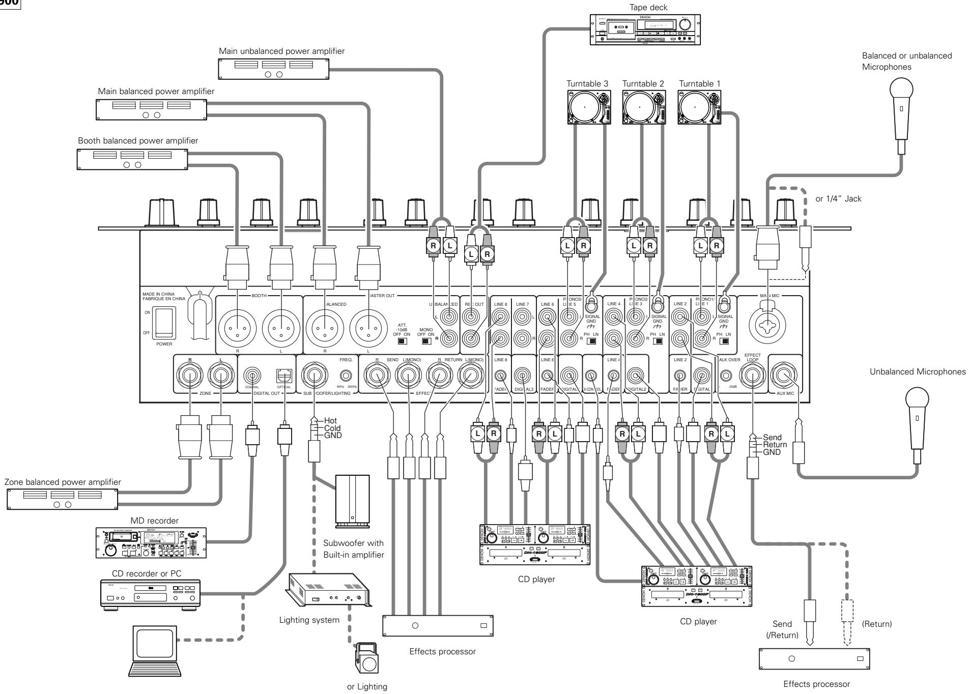
- Connect the stereo outputs to the power amplifier(s) and/or tape deck(s) and/or MD recorder(s) and/or CD recorder(s). Plug the DN-X500/DN-X900 into AC power outlet.
NOTE:
Always switch on your audio input sources such as CD players first, then your mixer, and finally any amplifiers. When turning off, always reverse this operation by turning off amplifiers, then your mixer, and then input units.
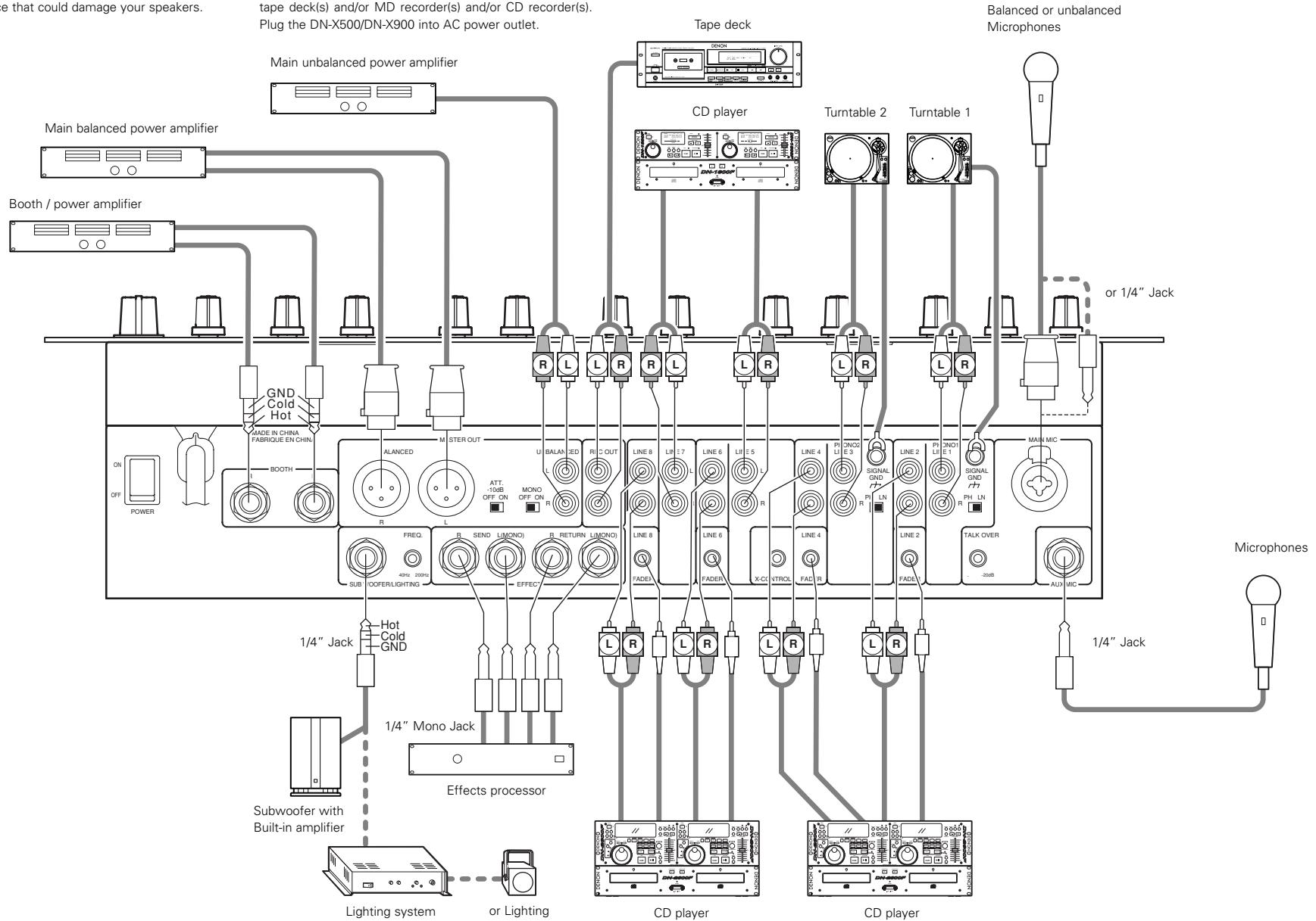
DN-X500
CONNECTIONS
DN-X900
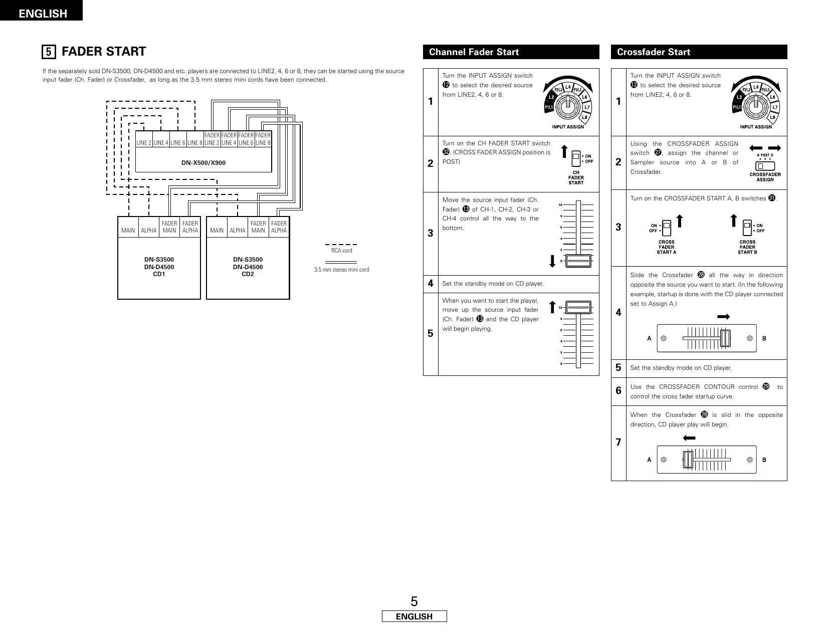
5 FADER START
If the separately sold DN-S3500, DN-D4500 and etc. players are connected to LINE2, 4, 6 or 8, they can be started using the source input fader (Ch. Fader) or Crossfader, as long as the 3.5mm stereo mini cords have been connected.
| 1 | Turn the INPUT ASSIGN switch 12 to select the desired source from LINE2, 4, 6 or 8. | INPUT ASSIGN |
| 2 | Turn on the CH FADER START switch 22. (CROSS FADER ASSIGN position is POST) | ↑ ON OFF CH FADER START |
| 3 | Move the source input fader (Ch. Fader) 13 of CH-1, CH-2, CH-3 or CH-4 control all the way to the bottom. | 10 8 6 4 2 10 0 |
| 4 | Set the standby mode on CD player. | |
| 5 | When you want to start the player, move up the source input fader (Ch. Fader) 13 and the CD player will begin playing. | 10 8 6 4 2 10 0 |
Crossfader Start
| 1 | Turn the INPUT ASSIGN switch ⑫ to select the desired source from LINE2, 4, 6 or 8. | INPUT ASSIGN |
| 2 | Using the CROSSFADER ASSIGN switch ⑦, assign the channel or Sampler source into A or B of Crossfader. | ←→ A POST B CROSSFADER ASSIGN |
| 3 | Turn on the CROSSFADER START A, B switches ③. | |
| ON OFF CROSS FADER START A | ↑ ↑ ON OFF CROSS FADER START B | |
| 4 | Slide the Crossfader ⑧ all the way in direction opposite the source you want to start. (In the following example, startup is done with the CD player connected set to Assign A.) | |
| A | B | |
| 5 | Set the standby mode on CD player. | |
| 6 | Use the CROSSFADER CONTOUR control ⑨ to control the cross fader startup curve. | |
| 7 | When the Crossfader ⑧ is slid in the opposite direction, CD player play will begin. | |
| A | B | |
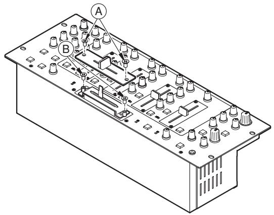
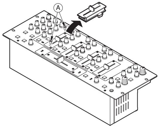
6 REPLACING THE CROSSFADE
The Crossfader may be removed without disassembly of DN-X500 and DN-X900 itself.
- Pull out the crossfader knob.
- Removed the two outer screws attaching the crossfader plate.
- Remove the two screws ⑧ attaching the crossfader bracket assembly from chassis.
- Pull the crossfader bracket assembly forward and unplug the 3P cable from the connector on the panel board.
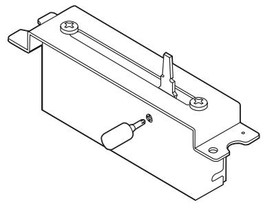
8 ONLY DN-X900 : FLEX FADER CROSSFAVER SLIDE TORQUE ADJUSTMENT PROCEDURE
- Follow the procedure at "REPLACING THE CROSSFADER" to remove the crossfader from the set.
- Move the lever so that the head of the screw is positioned at the hole in the case.
- Turn the screw using a screwdriver, move the lever and adjust to the desired torque.
- Reinstall the crossfader following the removal procedure in reverse order.
7 REPLACING THE CHANNEL FADER
The Channel fader may be removed without any disassembly of the DN-X500 and DN-X900 itself.
- Pull out the channel fader knob.
- Remove the two outer screws attaching the channel fader plate and channel fader bracket assembly from the front panel.
- Pull the channel fader bracket assembly forward and unplug the 3P cable from the connector on the channel fader printing board.
- Install the replacement assembly by reversing above instructions.
9 SPECIFICATIONS
DN-X500
GENERAL
Dimensions: 482 (W) x 112.5 (H) x 177 (D) mm (without feet)
Installation: 19-inch rack mountable 4U
Mass: 5.8kg
Power supply: 120 V AC ±10%, 60 Hz (U.S.A. and Canada models)
230 V AC ±10%, 50 Hz (European models)
Power consumption: 27 W
Environmental conditions: Operational temperature: 5 to 35^ (41 to 95^
Operational humidity: 25 to 85% (no condensation)
Storage temperature: -20 to 60^ (4 to 140^ )
■ AUDIO SECTION
Input Sensitivity & Impedance:
Main Mic -54 dBV (2.0 mV) 1 kΩ/kohms
Aux Mic -60 dBV (1.0 mV) 1 kΩ/kohms
Effect (Return) -14 dBV (200 mV) 50 kΩ/kohms
2-Phono -50 dBV (3.0 mV) 50 kΩ/kohms
8-Line -14 dBV (200 mV) 50 kΩ/kohms
Output level & Impedance:
Main (Balanced) 4 dBm (1.23 V) 600 Ω/ohms load
Main (Unbalanced) 0 dBV (1.0V) 1 kΩ/kohms
Booth(Balanced) 4 dBm (1.23 V) 600 Ω/ohms load
Rec (RCA) -10 dBV (316 mV) 1 kΩ/kohms
Effect (Send) -14 dBV (200 mV) 1 kΩ/kohms
Subwoofer 2 dB (0.975 V) 600 Ω/ohms
Headphone 0 dB (1.0 V) 32 Ω/ohms (33 Ω/ohms load)
Frequency Response:
Line 20 to 20kHz± 2 dB
Phono 20 to 20kHz RIAA ± 2 dB
Mic 20 to 20kHz± 2 dB
Signal to Noise ratio:
Line 82 dB 0 dBm,1 kHz, EQ flat
Phono 75 dB 0 dBm, 1 kHz, EQ flat
Main Mic 65 dB 0 dBm, 1 kHz, EQ flat
Total harmonic distortion rate:
Line Below 0.05%
Phono Below 0.05%
Cross talk: Over 70 dB
Channel equalizer:
+10 dB, -35 dB (16 kHz)
Mid +10 dB, -35 dB (1 kHz)
Low +6dB -35 dB (60 Hz)
Microphone equalizer:
+12 dB, -12 dB (10 kHz)
Mid +12dB, - 12dB (1 kHz)
Low +12dB, - 12dB (100Hz)
DN-X900
GENERAL
Dimensions: 482 (W) x 112.5 (H) x 177 (D) mm (without feet)
Installation: 19-inch rack mountable 4U
Mass: 5.9 kg
Power supply: 120 V AC ±10%, 60 Hz (U.S.A. and Canada models)
230 V AC ±10%, 50 Hz (European models)
Power consumption: 33 W
Environmental conditions: Operational temperature: 5 to 35^ (41 to 95^)
Operational humidity: 25 to 85% (no condensation)
Storage temperature: -20 to 60^ (4 to 140^ )
AUDIO SECTION
Input Sensitivity & Impedance:
Main Mic -54 dBV (2.0 mV) 10 kΩ/kohms
Aux Mic -60 dBV (1.0 mV) 10 kΩ/kohms
Effect (Return) -14 dBV (200 mV) 50 kΩ/kohms
3-Phono -50 dBV (3.0 mV) 50 kΩ/kohms
8-Line -14 dBV (200 mV) 50 kΩ/kohms
Output level & Impedance:
Main (Balanced) 4 dBm (1.23 V) 600 Ω/ohms load
Main (Unbalanced) 0 dBV (1.0 V) 1 kΩ/kohms
Zone (Balanced) 4 dBm (1.23 V) 600 Ω/ohms load
Booth(Balanced) 4 dBm (1.23 V) 600 Ω/ohms
Rec (RCA) -10 dBV (316 mV) 1 kΩ/kohms
Effect (Send) -14 dBV (200 mV) 1 kΩ/kohms
Subwoofer/Lighting(Balanced) 2 dBm (0.975 V) 600 Ω/ohms
Headphone 0 dBV (1.0 V) 32 Ω/ohms (33 Ω/ohms load)
Frequency Response:
Line 20 to 20kHz± 2 dB
Phono 20 to 20kHz RIAA ± 2 dB
Mic 20 to 20kHz ± 2 dB
Signal to Noise ratio:
Line 82 dB 0 dBm, 1 kHz, EQ flat
Phono 75 dB 0 dBm, 1 kHz, EQ flat
Main Mic 65 dB 0 dBm, 1 kHz, EQ flat
Total harmonic distortion rate:
Line Below 0.05%
Phono Below 0.05%
Cross talk: Over 70 dB
Channel equalizer:
+10 dB, -35 dB (16 kHz)
Mid +10 dB, -35 dB (1 kHz)
Low +6dB, - 35dB (60 Hz)
Microphone equalizer:
+12 dB, -12 dB (10 kHz)
Mid +12dB, - 12dB (1 kHz)
Low +12dB, - 12dB (100Hz)
Only DN-X900
Digital input:
Input sensitivity -26 dB FS
Signal format SPDIF (IEC60958 Type III 32kHz 48kHz24 bit) (COAXIAL)
Digital output:
Signal format IEC60958 Type II (OPTICAL, COAXIAL)
Output level 0.5 Vp-p 75 Ω/ohms (COAXIAL)
- INHALT -
3 MAIN MIC ON/OFF-Taste
36 MAIN OUT (BALANCED)-Anschlüsse
38 BOOTH OUT (BALANCED)-Anschlüsse
Line 82 dB 0 dBm, 1 kHz, EQ flach
Phono 75 dB 0 dBm, 1 kHz, EQ flach
Haupt-Mikro 65 dB 0 dBm, 1 kHz, EQ flach
Line 82 dB 0 dBm, 1 kHz, EQ flach
Phono 75 dB 0 dBm, 1 kHz, EQ flash
Haupt-Mikro 65 dB 0 dBm, 1 kHz, EQ flach
3 Touche MAIN MIC ON/OFF
8 Commandes Source EQ.
HI
3 Tasti MAIN MIC ON/OFF
15 Interruptor BOOTH ASSIGN
2 Interruptor EFFECT LOOP ASSIGN
230 V c.a. ±10%, 50 Hz
(Modelos Europeos)
Condiciones ambientales: Temperatura de funciona: 5 a 35^ (41 a 95^
Linea 82 dB 0 dBm, 1 kHz, EQ plano
Fono 75 dB 0 dBm, 1 kHz, EQ plano
Micrófono principal 65 dB 0 dBm, 1 kHz, EQ plano
Linea 82 dB 0 dBm, 1 kHz, EQ plano
Fono 75 dB 0 dBm, 1 kHz, EQ plano
Micrófono principal 65 dB 0 dBm, 1 kHz, EQ plano
6. 3-bands equalizer/gain
5 BOOTH ASSIGN-schakelaar
Tip: Send Ring: Return Sleeve: aarding
AANSLUITINGEN
Line 82 dB 0 dBm, 1 kHz, EQ vlak
Phono 75 dB 0 dBm, 1 kHz, EQ vlak
Main mic 65 dB 0 dBm, 1 kHz, EQ vlak
Headphone 0 dBV (1,0 V) 32 Ω/ohm (33 Ω/ohm belasting)
Frequentiewergave:
Line 20 tot 20kHz ± 2 dB
Phono 20 tot 20 kHz RIAA ± 2 dB
Mic 20 tot 20 kHz ±2 dB
Line 82 dB 0 dBm,1 kHz, EQvlak
Phono 75 dB 0 dBm, 1 kHz, EQ VLC
Main mic 65 dB 0 dBm, 1 kHz, EQ vlak
3 MAIN MIC ON/OFF-tangent
Total harmonisk distorsion:
Line Under 0,05 %
Phono Under 0,05 %
Overhörning:
Equalizer:
+10 dB, -35 dB (16 kHz)
Mid +10 dB, -35 dB (1 kHz)
Low +6dB, - 35dB (60Hz)
Mikrofon-equalizer:
+12 dB, -12 dB (10 kHz)
Mid +12 dB, -12 dB (1 kHz)
Low +12dB, - 12dB (100Hz)
DN-X900
ALLMANT
Matt: 482 (B) x 112,5 (H) x 177 (D) mm (utan fötter)
Installation: 19-tums rack med 4U-installation
Vikt: 5,9 kg
Total harmonisk distorsion:
Line Under 0,05 %
Phono Under 0,05 %
Overhörning: Over 70 dB
Equalizer:
Hi +10 dB, -35 dB (16 kHz)
Mid +10dB, - 35dB (1 kHz)
Low +6dB, - 35dB (60Hz)
Mikrofon-equalizer:
Hi +12 dB, -12 dB (10 kHz)
Mid +12dB, - 12dB(1kHz)
Low +12dB, - 12dB (100Hz)
Endart DN-X900
Digital ingang:
Inkansliget -26 dB FS
Signalformat SPDIF (IEC60958-Typ III 32 kHz 48 kHz 24 bit) (COAXIAL)
Digital utgang:
Signalformat IEC60958-Typ II (OPTICAL, COAXIAL)
Utnivá 0,5 Vp-p 75 Ω/ohm (COAXIAL)
警告
- CAUTION
- RISK OF ELECTRIC SHOCK DO NOT OPEN
- IMPORTANT SAFETY INSTRUCTIONS
- CAUTION:
- Handle the power supply cord carefully
- Do not open the top cover
- Do not place anything inside
- FCC INFORMATION (For US customers)
- 1.PRODUCT
- IMPORTANT NOTICE: DO NOT MODIFY THIS PRODUCT
- NOTE
- HINWEIS ZUM RECYCLING:
- ACHTUNG:
- - ACCESSORIES
- MAIN FEATURES
- Matrix input assignment
- 60 MM Channel Fader (Replaceable)
- Level Mater per Channel
- Booth Assign
- Enhanced SEND/RETURN terminals
- 3-Band equalizer/gain
- INSTALLATION
- Crossfader Contour
- Channel Fader and Crossfader Start
- Crossfader Control Output
- Mic Post (Att Level adjusted)
- Hi-Grade Type Op Amp
- Only DN-X900 : Digital Input/Output
- Only DN-X900 : FLEX FADER (Adjustable Slide Torque Crossfader.)
- PART NAMES AND FUNCTIONS
- Front Panel
- MIC EQ controls
- HI
- MID
- LOW
- MAIN MIC level control
- MAIN MIC ON/OFF button
- MIC POST ON/OFF button
- AUX MIC level control
- AUX MIC ON/OFF button
- TALK OVER ON/OFF button
- Source EQ controls
- EQ ON/ OFF buttons
- GAIN level control
- CH LEVEL meter
- SOURCE INPUT ASSIGN (Input selectors)
- Source input fader (Ch. fader)
- BOOTH level control
- BOOTH ASSIGN switch
- MASTER LEVEL control
- MASTER BALANCE control
- Peak dB CUE/PROGRAM meter
- EFFECT LOOP ON/OFF button
- EFFECT LOOP WET/DRY control
- EFFECT LOOP ASSIGN switch
- HEADPHONE output jack
- HEADPHONE level control
- FADER START
- Rear Panel
- CONNECTIONS
- CONNECTIONS
- FADER START
- Crossfader Start
- REPLACING THE CROSSFADE
- ONLY DN-X900 : FLEX FADER CROSSFAVER SLIDE TORQUE ADJUSTMENT PROCEDURE
- REPLACING THE CHANNEL FADER
- SPECIFICATIONS
- DN-X500
- ■ AUDIO SECTION
- DN-X900
- - INHALT -
- MAIN MIC ON/OFF-Taste
- Touche MAIN MIC ON/OFF
- Commandes Source EQ.
- Tasti MAIN MIC ON/OFF
- Interruptor BOOTH ASSIGN
- 3-bands equalizer/gain
- BOOTH ASSIGN-schakelaar
- AANSLUITINGEN
- Frequentiewergave:
- MAIN MIC ON/OFF-tangent
- ALLMANT
- 警告
Brand : DENON
Model : DN-X900
Category : DJ Mixer