Parts available through DENON authorized service, support duration 10 years
General Information
Compliant with CE standards (EN60065, EN55013, etc.); WEEE recycling
Frequently Asked Questions - AVR-1909 DENON
How to perform automatic setup with Audyssey MultEQ?
Place the included microphone at the listening position, then go to the 'Setup' menu and select 'Audyssey MultEQ'. Follow the on-screen instructions to perform the measurements. The device automatically calculates the equalization parameters.
What audio formats are supported by the DENON AVR-1909?
The receiver supports Dolby TrueHD, DTS-HD Master Audio, Dolby Digital Plus, DTS-HD, Multichannel PCM, and standard Dolby/DTS formats.
Can I connect multiple HDMI sources?
Yes, the DENON AVR-1909 has 3 HDMI inputs and 1 HDMI output. You can connect your sources (Blu-ray player, console, etc.) and switch between them using the remote control or the front panel.
How to clean the device without damaging it?
Use a soft, dry cloth. Never use solvents, chemicals, or sprays. Unplug the device before cleaning.
What to do if the device does not turn on?
Check that the power cord is properly plugged in and that the wall outlet is working. If the problem persists, contact a DENON authorized service center.
How to tune the AM/FM radio?
Connect the supplied AM and FM antennas. Press 'Tuner' to select the band, then use the search keys or presets to find stations.
What is the output power per channel?
The DENON AVR-1909 delivers 90 watts per channel RMS into 8 ohms, with all channels driven.
Can I use the receiver with a passive subwoofer?
No, the subwoofer output is designed for an active (amplified) subwoofer. For a passive subwoofer, you need an external amplifier.
How to update the firmware?
This model does not have firmware update capability via USB or network; settings are fixed at the factory.
How to dispose of the device at end of life?
Follow WEEE recycling laws. Take the device to an authorized collection point or contact your local municipality.
User questions about AVR-1909 DENON
1 question about this device. Answer the ones you know or ask your own.
Ask a new question about this device
How to use the Power button on the DENON AVR-1909 audio-video receiver?
Frequently Asked Questions -26/11/2025
Response Notice-Facile
The Power button on the DENON AVR-1909 audio-video receiver controls the device's power in two stages: standby and full power. Here’s how to use it correctly.
Standby: Press the POWER button located on the front panel. The indicator light turns red, indicating that the device is entering standby mode. In this mode, the device consumes little energy but remains ready to start quickly.
Full power: Once in standby mode, press the ON/STANDBY button (located on the front panel) or the [ON/SOURCE] button on the remote control. The indicator light blinks green and the device powers on completely. You can also turn on the device by pressing an input selection button (SOURCE SELECT) or a Quick Select button on the remote control.
Turning off the device: To completely turn off the receiver, press the ON/STANDBY button on the front panel or the [OFF] button on the remote control. The device returns to standby mode with the red light on.
Important: In standby mode, the device continues to consume a small amount of energy. For a complete disconnection from the power supply, unplug the power cord from the wall outlet, especially if you do not plan to use the device for an extended period.
Indicator lights: The Power indicator located on the front panel allows you to check the device's status: red in standby mode, blinking green during startup, solid green once fully operational.
Respond (be the first)
Download the instructions for your AV receiver in PDF format for free! Find your manual AVR-1909 -
DENON and take your electronic device back in hand. On this page are published all the documents necessary for the use of your device. AVR-1909 by DENON.
USER MANUAL AVR-1909 DENON
The lightning flash with arrowhead symbol, within an equilateral triangle, is intended to alert the user to the presence of uninsulated “dangerous voltage” within the product’s enclosure that may be of sufficient magnitude to constitute a risk of electric shock to persons.
The exclamation point within an equilateral triangle is intended to alert the user to the presence of important operating and maintenance (servicing) instructions in the literature accompanying the appliance.
WARNING:
TO REDUCE THE RISK OF FIRE OR ELECTRIC SHOCK, DO NOT EXPOSE THIS APPLIANCE TO RAIN OR MOISTURE.
- DECLARATION OF CONFORMITY
We declare under our sole responsibility that this product, to which this declaration relates, is in conformity with the following standards: EN60065, EN55013, EN55020, EN61000-3-2 and EN61000-3-3. Following the provisions of 2006/95/EC and 2004/108/EC Directive.
Division of D&M Germany GmbH
An der Landwehr 19, Nettetal,
D-41334 Germany
CAUTION:
To completely disconnect this product from the mains, disconnect the plug from the wall socket outlet.
The mains plug is used to completely interrupt the power supply to the unit and must be within easy access by the user.
VORSICHT:
natural_image
Cartoon illustration of a sun with angry face and water droplets, next to a damaged box (no text or symbols)
- Avoid high temperatures.
Allow for sufficient heat dispersion when installed in a rack.
- Handle the power cord carefully.
Hold the plug when unplugging the cord.
natural_image
Cartoon illustration of a sad rectangular object with eyes and nose, surrounded by small droplets (no text or symbols)
- Keep the unit free from moisture, water, and dust.
- Unplug the power cord when not using the unit for long periods of time.
* (For apparatuses with ventilation holes)
- Do not obstruct the ventilation holes.
- Do not let foreign objects into the unit.
- Do not let insecticides, benzene, and thinner come in contact with the unit.
- Never disassemble or modify the unit in any way.
The ventilation should not be impeded by covering the ventilation openings with items, such as newspapers, tablecloths, curtains, etc.
No naked flame sources, such as lighted candles, should be placed on the unit.
Observe and follow local regulations regarding battery disposal.
Do not expose the unit to dripping or splashing fluids.
Do not place objects filled with liquids, such as vases, on the unit.
ACHTUNG:
A NOTE ABOUT RECYCLING:
This product's packaging materials are recyclable and can be reused. Please dispose of any materials in accordance with the local recycling regulations.
When discarding the unit, comply with local rules or regulations.
Batteries should never be thrown away or incinerated but disposed of in accordance with the local regulations concerning battery disposal.
This product and the supplied accessories, excluding the batteries, constitute the applicable product according to the WEEE directive.
HINWEIS ZUM RECYCLING:
Cautions on Handling 3
Cautions on Installation 3
About the Remote Control Unit....3
Inserting the Batteries 3
Operating Range of the Remote Control Unit......4
Part Names and Functions ....4
Front Panel 4
Display 5
Rear Panel 6
Remote Control Unit 7
Connections
Preparations......8
Cables Used for Connections 8
Video Conversion Function 9
About On-screen Displays due to Input Signals....9
Speaker Connections 9
Speaker Installation....9
Speaker Connections 10
Connecting Equipment with HDMI connectors.... 11
Connecting the Monitor....12
Connecting the Playback Components 12
Blu-ray Disc player / DVD player 12
CD Player 13
iPod ^® 13
TV/CABLE Tuner 13
Connecting the Recording Components 14
Video Cassette Recorder 14
CD Recorder / MD Recorder / Tape Deck 14
Connections to Other Devices 14
Video Camera / Game Console 14
Component with Multi-channel Output connectors.... 15
Antenna terminals 15
Multi-zone 16
External Controller 16
Connecting the Power Cord 16
Once Connections are Completed 16
Menu Operations
Operations....17
Example of Display of Default Values 17
Examples of On-screen Display and Front Display 18
Menu Map 19
Auto Setup
Preparations....20
Auto Setup 21
1 Start Menu....21
2 Parameter Check 23
Error Messages....23
Manual Setup
Speaker Setup 24
1 Speaker Configuration....24
2 Subwoofer Setup 25
3 Distance 25
4 Channel Level 25
5 Crossover Frequency 26
6 Front Speaker Setup 26
HDMI Setup 26
1 Color Space 26
2 RGB Range 26
3 Auto Lipsync 26
4 HDMI Audio Out 26
5 HDMI Control 26
6 Power Off Control 27
Audio Setup 27
1 EXT. IN Subwoofer Level 27
2 2ch Direct/Stereo 27
3 Dolby Digital Setup 28
4 Auto Surround Mode 28
5 EQ Preset 28
ZONE2 Setup 29
1 Level Lch....29
2 Level Rch 29
3 Volume Limit 29
4 Power On Level 29
5 Mute Level 29
Option Setup....29
1 Amp Assign....29
2 Volume Control 30
3 Source Delete 30
4 On-Screen Display 30
5 Quick Select Name 31
6 Remote ID Setup 31
7 2Way Remote 31
8 Display 31
9 Setup Lock 31
Input Setup
Settings Related to Playing Input Sources 33
1 Auto Preset 33
2 Preset Skip 33
3 Preset Name 33
4 Video 33
5 Input Mode 34
6 Rename....35
7 Source Level 35
8 Assign 35
9 iPod 36
Surround Modes
① Standard Playback 36
Surround Playback of 2-channel Sources 36
Playing Multi-channel Sources (Dolby Digital, DTS, etc.)……37
② DSP Simulation Playback 37
③ Direct Playback 37
④ Stereo Playback 37
Playback in the PURE DIRECT Mode 38
Parameter
Adjusting the parameters....38
Surround Parameter....39
Surround Parameter 39
Tone 41
Audyssey Settings 41
RESTORER 43
Night Mode 43
Audio Delay 43
Information
Status 44
1 MAIN ZONE 44
2 ZONE2 44
Audio Input Signal 44
HDMI Information 45
1 HDMI Signal Information 45
2 HDMI Monitor Information 45
Auto Surround Mode 45
Quick Select 45
Preset Station 45
Playback
Preparations......46
Turning the Power On 46
Selecting the Input Source 46
Operations During Playback 46
Basic Operation....50
Listening to Music 51
Viewing Still Pictures or Videos on the iPod 51
Other Operations and Functions
Other Operations....52
Recording on an External Equipment (REC OUT mode) 52
Convenient Functions 53
HDMI Control Function 53
Channel Level 54
Fader Function 54
Quick Select Function 55
Personal Memory Plus Function 55
Last Function Memory 55
Backup Memory 55
Resetting the Microprocessor 55
Remote Control Unit Operations
Operating DENON Audio Components 56
Presetting 56
Operating Preset Components....56
Punch Through Function 59
Amp Assign / Multi-zone Connections and Operations
Multi-zone Settings with the Amp Assign Function....60
Multi-zone Settings and Operations with Zone Output 61
Multi-zone Operations 62
Turning the Power On and Off....62
Selecting the Input Source 62
Adjusting the Volume 62
Turning off the Sound Temporarily 62
Other Information 63
Troubleshooting 71
Specifications 74
List of preset codes....End of this manual
Getting Started
Thank you for purchasing this DENON product. To ensure proper operation, please read this owner's manual carefully before using the product.
After reading them, be sure to keep them for future reference.
Accessories
Check that the following parts are supplied with the product.
① Owner's manual....1
② Getting Started....1
③ Service station list .... 1
④ Power cord (Cord length: Approx. 1.6 m)....1
⑤ Remote control (RC-1099)....1
⑥ R6/AA batteries 2
⑦ FM indoor antenna 1
⑧ AM loop antenna....1
⑨ Setup microphone
(DM-A409, Cord length: Approx. 7.6 m)....1
④
⑤
⑦
⑧
⑨
Cautions on Handling
• Before turning the power switch on
Check once again that all connections are correct and that there are no problems with the connection cables.
- Power is supplied to some of the circuitry even when the unit is set to the standby mode. When traveling or leaving home for long periods of time, be sure to unplug the power cord from the power outlet.
- About condensation
If there is a major difference in temperature between the inside of the unit and the surroundings, condensation (dew) may form on the operating parts inside the unit, causing the unit not to operate properly.
If this happens, let the unit sit for an hour or two with the power turned off and wait until there is little difference in temperature before using the unit.
- Cautions on using mobile phones
Using a mobile phone near this unit may result in noise. If so, move the mobile phone away from this unit when it is in use.
- Moving the unit
Turn off the power and unplug the power cord from the power outlet.
Next, disconnect the connection cables to other system units before moving the unit.
- Note that the illustrations in these instructions may differ from the actual unit for explanation purposes.
Cautions on Installation
Note:
For proper heat dispersal, do not install this unit in a confined space, such as a bookcase or similar enclosure.
About the Remote Control Unit
In addition to the AVR-1909, the included remote control unit (RC-1099) can also be used to operate the equipment listed below.
① DENON system components
② Non-DENON system components
- By setting the preset memory (page 56 \~ 58)
Inserting the Batteries
① Lift the clasp and remove the rear cover.
② Load the two batteries properly as indicated by the marks in the battery compartment.
③ Put the rear cover back on.
NOTE
Replace the batteries with new ones if the set does not operate even when the remote control unit is operated close to the unit.
The supplied batteries are only for verifying operation.
When inserting the batteries, be sure to do so in the proper direction, following the “⊕” and “⊖” marks in the battery compartment.
To prevent damage or leakage of battery fluid:
Do not use a new battery together with an old one.
Do not use two different types of batteries.
Do not attempt to charge dry batteries.
Do not short-circuit, disassemble, heat or dispose of batteries in flames.
If the battery fluid should leak, carefully wipe the fluid off the inside of the battery compartment and insert new batteries.
Remove the batteries from the remote control unit if it will not be in use for long periods.
When replacing the batteries, have the new batteries ready and insert them as quickly as possible.
Operating Range of the Remote Control Unit
Point the remote control unit at the remote sensor when operating it.
NOTE
The set may function improperly or the remote control unit may not operate if the remote control sensor is exposed to direct sunlight, strong artificial light from an inverter type fluorescent lamp or infrared light.
Part Names and Functions
For buttons not explained here, see the page indicated in parentheses ( ).
Front Panel
① Power operation button (ON/STANDBY) ...... (46)
② Power indicator ...... (46)
③ Power switch (ON OFF) ...... (46)
4 Headphones jack (PHONES)......(46)
⑤ INPUT MODE button …… (15, 34)
⑥ SPEAKERS button …… (26, 46)
⑦ ZONE2 ON/OFF button …… (62)
8 QUICK SELECT buttons ...... (55)
9 V. AUX INPUT connectors....(14)
Remove the cap covering the terminals when you want to use them.
natural_image
Diagram of a computer monitor front panel with indicator lights and ports (no text or labels)
Audyssey Dynamic Volume™ solves the problem of large variations in volume level between television programs, commercials, and between the soft and loud passages of movies.
Audyssey Dynamic EQ ^™ is integrated into Dynamic Volume so that as the playback volume is adjusted automatically, the perceived bass response, tonal balance, surround impression, and dialog clarity remain the same.
※ About Dynamic EQ
Audyssey Dynamic EQ solves the problem of deteriorating sound quality as volume is decreased by taking into account human perception and room acoustics. Audyssey Dynamic EQ works in tandem with Audyssey MultEQ ^® to provide well-balanced sound for every listener at any volume level.
33 RDS button (48, 49)
Display
① Input signal indicators
② Input signal channel indicators
These light when digital signals are input.
③ Information display
The input source name, surround mode, setting values and other information are displayed here.
4 Output signal channel indicators
⑤ Front speaker indicator
These light according to the settings of the front A and B speakers.
⑥ ZONE2 output indicator
This lights when the power for the ZONE2 is turned on.
⑦ Master volume indicator
8 AUDYSSEY MULTEQ indicator
This lights when the MultEQ is selected.
⑨ Input mode indicators
10 Recording output source indicator
This lights when the REC OUT mode is selected.
11 NIGHT indicator
This lights when the night mode is selected.
⑫ RESTORER indicator
This lights when the RESTORER mode is selected.
13 HDMI indicator
This lights when playing using HDMI connections.
14 Decoder indicators
These light when the respective decoders are operating.
15 Tuner reception mode indicators
This lights according to the reception conditions when the input source is set to "TUNER".
• AUTO
This lights when in the auto tuning mode.
• STEREO
In the FM mode, this lights when receiving analog stereo broadcasts.
• TUNED
This lights when the broadcast is properly tuned in.
• RDS
This lights when receiving RDS broadcasts.
Rear Panel
① Digital audio connectors (OPTICAL / COAXIAL) …… (12 \~ 14)
② Analog audio connectors (AUDIO) …… (12 \~ 14)
③ EXT. IN connectors....(15)
4 REMOTE CONTROL jacks ...... (16)
⑤ PRE OUT connector....(10)
6 ZONE2 connectors ...... (16)
⑬ DOCK CONTROL jack …… (13)
14 VIDEO / S-VIDEO connectors.... (12 \~ 14)
⑮ COMPONENT VIDEO connectors....(12, 13)
Remote Control Unit
[ Front ]
① Indicator …… (56)
② Power buttons ...... (46)
③ QUICK SELECT buttons ...... (46, 55)
4 Source select buttons ...... (46)
⑤ System buttons ...... (51)
⑥ AUDIO DELAY button …… (43)
⑦ Cursor buttons (△▽◀ ▷) …… (38)
⑧ DYNAMIC VOLUME button …… (42)
⑨ RESTORER button …… (43)
10 SOURCE CONTROL switches.... (17, 56)
11 Remote control signal transmitter ..... (4)
⑫ Master volume control buttons …… (46)
13 MUTING button....(46)
14 NIGHT button ...... (43)
15 MULTEQ button ...... (41)
16 Channel select (CH SEL) / ENTER button....(38)
SOURCE CONTROL switch settings and operable buttons
□ When operating MAIN ZONE
flowchart
graph TD
    A["AUDIO"] --> B["VIDEO"]
    B --> C["CD"]
    C --> D["TUNER"]
    D --> E["TV"]
    E --> F["SAT/CABLE"]
    G["CD", "iPod/NETWORK" or "TUNER"] --> H["SOURCE CONTROL"]
□ When operating ZONE2
flowchart
graph LR
    A["“AUDIO”"] --> B["VIDEO"]
    B --> C["VIDEO"]
    C --> D["VIDEO"]
    D --> E["VIDEO"]
    E --> F["VIDEO"]
    F --> G["VIDEO"]
    G --> H["VIDEO"]
    H --> I["VIDEO"]
    I --> J["VIDEO"]
    J --> K["VIDEO"]
    K --> L["VIDEO"]
    L --> M["VIDEO"]
    M --> N["VIDEO"]
    N --> O["VIDEO"]
    O --> P["VIDEO"]
    P --> Q["VIDEO"]
    Q --> R["VIDEO"]
    R --> S["VIDEO"]
    S --> T["VIDEO"]
    T --> U["VIDEO"]
    U --> V["VIDEO"]
    V --> W["VIDEO"]
    W --> X["VIDEO"]
    X --> Y["VIDEO"]
    Y --> Z["VIDEO"]
    Z --> AA["VIDEO"]
    AA --> AB["VIDEO"]
    AB --> AC["VIDEO"]
    AC --> AD["VIDEO"]
    AD --> AE["VIDEO"]
    AE --> AF["VIDEO"]
    AF --> AG["VIDEO"]
    AG --> AH["VIDEO"]
    AH --> AI["VIDEO"]
    AI --> AJ["VIDEO"]
    AJ --> AK["VIDEO"]
    AK --> AL["VIDEO"]
    AL --> AM["VIDEO"]
    AM --> AN["VIDEO"]
    AN --> AO["VIDEO"]
    AO --> AP["VIDEO"]
    AP --> AQ["VIDEO"]
    AQ --> AR["VIDEO"]
    AR --> AS["VIDEO"]
    AS --> AT["VIDEO"]
    AT --> AU["VIDEO"]
    AU --> AV["VIDEO"]
    AV --> AW["VIDEO"]
    AW --> AX["VIDEO"]
    AX --> AY["VIDEO"]
    AY --> AZ["VIDEO"]
    AZ --> BA["VIDEO"]
    BA --> BB["VIDEO"]
    BB --> BC["VIDEO"]
    BC --> BD["VIDEO"]
    BD --> BE["VIDEO"]
    BE --> BF["VIDEO"]
    BF --> BG["VIDEO"]
    BG --> BH["VIDEO"]
    BH --> BI["VIDEO"]
    BI --> BJ["VIDEO"]
    BJ --> BK["VIDEO"]
    BK --> BL["VIDEO"]
    BL --> BM["VIDEO"]
    BM --> BN["VIDEO"]
    BN --> BO["VIDEO"]
    BO --> BP["VIDEO"]
    BP --> BQ["VIDEO"]
    BQ --> BR["VIDEO"]
    BR --> BS["VIDEO"]
    BS --> BT["VIDEO"]
    BT --> BU["VIDEO"]
    BU --> BV["VIDEO"]
    BV --> BW["VIDEO"]
    BW --> BX["VIDEO"]
    BX --> BY["VIDEO"]
    BY --> BZ["VIDEO"]
    BZ --> CA["VIDEO"]
    CA --> CB["VIDEO"]
    CB --> CC["VIDEO"]
    CC --> CD["VIDEO"]
    CD --> CE["VIDEO"]
    CE --> CF["VIDEO"]
    CF --> CG["VIDEO"]
    CG --> CH["VIDEO"]
    CH --> CI["VIDEO"]
    CI --> CJ["VIDEO"]
    CJ --> CK["VIDEO"]
    CK --> CR["VIDEO"]
    CR --> CS["VIDEO"]
    CS --> CT["VIDEO"]
    CT --> CU["VIDEO"]
    CU --> CV["VIDEO"]
    CV --> CW["VIDEO"]
    CW --> CX["VIDEO"]
    CX --> CY["VIDEO"]
    CY --> CZ["VIDEO"]
    CZ --> DA["VIDEO"]
    DA --> DB["VIDEO"]
    DB --> DC["VIDEO"]
    DC --> DD["VIDEO"]
    DD --> DE["VIDEO"]
    DE --> DF["VIDEO"]
    DF --> DG["VIDEO"]
    DG --> DH["VIDEO"]
    DH --> DI["VIDEO"]
    DI --> DJ["VIDEO"]
    DJ --> DK["VIDEO"]
    DK --> DL["VIDEO"]
    DL --> DJ
NOTE
With this setting, only ZONE2 buttons can be operated. See page 62 for operable buttons.
NOTE
The SAT TU1/2 button cannot be used.
If buttons on the front or rear are pressed strongly, the button on the opposite side will be activated too.
[Rear]
① ZONE2 power buttons ...... (62)
② Source select buttons ...... (46)
③ Video select button (V.SEL)....(33)
④ Tuner system buttons......(47)
⑤ Test tone button (TEST) ...... (25)
⑥ MAIN ZONE power buttons (MAIN) …… (62)
⑦ Surround mode buttons …… (37, 38)
⑧ Amp menu button (A. MENU)...... (17)
⑨ Input mode button (INPUT)....(15, 34)
⑩ Enter button (ENT) ...... (17, 38)
⑪ RETURN button …… (17)
⑫ Cursor buttons (△▽◀ ▷) …… (17)
Connections
Connections for all compatible audio and video signal formats are described in this owner's manual. Please select the types of connections suited for the equipment you are connecting.
With some types of connections, certain settings must be made on the AVR-1909. For details, refer to the instructions for the respective connection items below.
NOTE
Do not plug in the power cord until all connections have been completed.
When making connections, also refer to the operating instructions of the other components.
Be sure to connect the left and right channels properly (left with left, right with right).
Do not bundle power cords together with connection cables. Doing so can result in humming or noise.
Preparations
Cables Used for Connections
Select the cables according to the equipment being connected.
Audio cables
Video cables
Coaxial digital connections(Orange: [H60Y] [WW05] [EDD] [SH80] [CHAT] [YYW0] [HOLZ] [OWT]Coaxial digital (75 Ω/ohms pin-plug) cableOptical digital connectionsOptical cableAnalog connections (stereo)(White) (Red) Stereo pin-plug cableAnalog connections (monaural, for subwoofer)(Black) Pin-plug cableSpeaker connections+ Speaker cables
Component video connections(Green) Component video cable(PB/CB) S-Video connections(S-Video cableVideo connections(Yellow) 75 Ω/ohms pin-plug video cable
This function automatically converts various formats of video signals input to the AVR-1909 into the format used to output the video signals from the AVR-1909 to a monitor.
The AVR-1909's video input/output circuitry is compatible with the following four types of video signals: Digital video signals : HDMI
Analog video signals: Component video, S-Video and Video
【Flow of video signals inside the AVR-1909】
flowchart
graph TD
    A["High picture quality playback"] --> B["HDMI connector"]
    A --> C["Component video connectors"]
    A --> D["S-Video connector"]
    A --> E["Video connector"]
    B --> F["HDMI connector"]
    C --> G["Component video connectors"]
    D --> H["S-Video connector"]
    E --> I["Video connector"]
    F --> J["Monitor output terminals"]
    G --> J
    H --> J
    I --> J
    J --> K["Monitor"]
    style A fill:#f9f,stroke:#333
    style K fill:#ccf,stroke:#333
When not using this function, connect a monitor output with the same type of connector as the video input connector.
The resolution of the HDMI input-compatible monitor connected to the AVR-1909 can be checked at menu “Information” – “HDMI Information” (page 45).
NOTE
HDMI signals cannot be converted into analog signals.
1080p component video input signals cannot be output to anything other than component video connectors.
480p/576p, 1080i and 720p component video input signals cannot be converted into S-Video or Video format.
When a non-standard video signal from a game machine or some other source is input, the video conversion function might not operate.
About On-screen Displays due to Input Signals
The method of on-screen display (OSD) varies with the type of video signal input to AVR-1909.
Video signal being used
Menu display
Momentary status display when operating(Display when changing the input source, volume, etc.)
HDMI connector / Component video connectors
OSD only display
Turn display off
S-Video connector / Video connector
Display of OSD superimposed on the input image
Turn display on
Speaker Connections
Speaker Installation
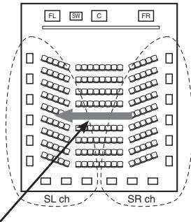
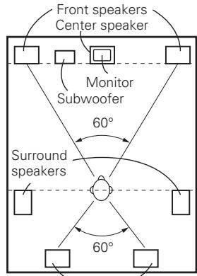
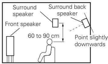
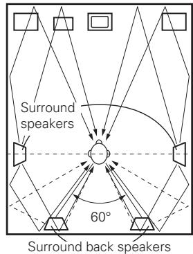
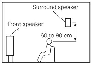
The illustration below shows a basic example (7.1-channel) of installation of the amplifier combined with 8 speakers and a monitor.
Front speakers
Place the front speakers to the sides of the monitor or screen and as flush with the screen surface as possible.
The table below shows a typical speaker configuration for the AVR-1909.
For surround back speakers :
When using just one surround back speaker, connect it to the left channel (SBL).
For ZONE2 speakers :
When outputting audio from the surround back speakers with ZONE2, set to "ZONE2" with "Manual Setup" – "Option Setup" – "Amp Assign" from the menu. For multi-zone connection and operation, see "Amp Assign / Multi-zone Connections and Operations" (page 60 \~ 62).
Connecting the Speaker Cables
Carefully check the left (L) and right (R) channels and + (red) and – (black) polarities on the speakers being connected to the AVR-1909, and be sure to interconnect the channels and polarities correctly.
1 Peel off about 10 mm of sheathing from the tip of the speaker cable, then either twist the core wire tightly or terminate it.
2 Turn the speaker terminal counterclockwise to loosen it.
3 Insert the speaker cable's core wire to the hilt into the speaker terminal.
4 Turn the speaker terminal clockwise to tighten it.
NOTE
Use speakers with an impedance of 6 to 16/ ohms. When using front A and B speakers simultaneously, use speakers with an impedance of 12 to 16/ ohms.
Connect the speaker cables in such a way that they do not stick out of the speaker terminals. The protection circuit may be activated if the core wires touch the rear panel or if the + and – sides touch each other (☐ “Protection circuit”).
Never touch the speaker terminals while the power supply is connected. Doing so could result in electric shock.
Protection circuit
If the core wires touch the rear panel and the screws etc., or the ± sides touch each other, the protection circuit will be activated and the power indicator will flash red at intervals of 0.5 secs.
If the protection circuit is activated, the speaker output is isolated, and the power supply goes to the standby state. If the power supply is turned off, after the power supply cord is withdrawn, please confirm that speaker cable and input cable are connected.
Also, if replaying large sound levels by using a speaker having an impedance less than that specified (eg, 4 Ω/ohms), the temperature will rise, and the protection circuit might be activated. The power supply will go into the standby state, and the power indicator will flash red at 2 second intervals.
In this case, please switch off the power supply, and wait until the AVR-1909 has cooled down, and the surrounding ventilation is good.
Even if there are no problems with the surrounding ventilation and connections, in the event of the protection circuit becoming activated, due to thinking that the AVR-1909 has failed, please contact DENON Service center after switching off.
Connecting Equipment with HDMI connectors
With HDMI connections, the video and audio signals can be transferred with a single cable.
※ The AVR-1909 is equipped for HDMI version 1.3a. This version is compatible with other versions, allowing connection to all components equipped with an HDMI connector.
※ The AVR-1909 is compatible with 30- and 36-bit Deep Color.
Compatible audio format
Details
Discs (examples)
2-channel linear PCM
2ch 32-192 kHz 16/20/24 bits
CD, DVD-Video, DVD-Audio
Multi-channel linear PCM
8ch 32-192 kHz 16/20/24 bits
DVD-Audio, Blu-ray
Dolby Digital, DTS
Bitstream
DVD-Video
Dolby Digital Plus, Dolby TrueHD, DTS-HD
Bitstream
Blu-ray
By default, the HDMI audio signals are output from the speakers connected to the AVR-1909.
To output the sound from the TV, make the settings at menu "Manual Setup" – "HDMI Setup" – "HDMI Audio Out" – "TV" (page 26).
NOTE
The audio signals output from the HDMI connector (sampling frequency, bit rate, etc.) may be restricted by the connected device.
Video signals are not output properly when using devices that are not HDCP-compatible.
Video signals are not output if the input video signals do not match the monitor's resolution. In this case, switch the Blu-ray Disc player / DVD player's resolution to a resolution with which the monitor is compatible.
If the menu “Manual Setup” – “HDMI Setup” – “HDMI Audio Out” setting (page 26) is set to “AMP”, the sound may be interrupted when the monitor’s power is turned off.
Use a cable on which the HDMI logo is indicated (a certified HDMI product) for connection to the HDMI connector. Normal playback may not be possible when using a cable other than one on which the HDMI logo is indicated (a non-HDMI-certified product).
If the monitor or Blu-ray Disc player / DVD player does not support Deep Color, deep color signal transfer is not possible.
If the monitor or Blu-ray Disc player / DVD player does not support xvYCC, xvYCC signal transfer is not possible.
If the monitor does not support "Auto Lipsync Correction" function, this function will not work.
The AVR-1909 is compatible with the HDMI's CEC (Consumer Electronics Control) function. Please note the following.
- It may not work depending on the device it is connected to and its setup.
- It does not operate with televisions or players that are not compatible with HDMI's CEC.
When the AVR-1909 and Blu-ray Disc player / DVD player are connected using an HDMI cable, also connect the AVR-1909 and monitor using an HDMI cable.
If the connected monitor or Blu-ray Disc player / DVD player only has a DVI-D connector, use an HDMI/ DVI converter cable. When using a DVI cable, no audio signals are transmitted.
Use a Deep Color compatible cable for connection to Deep Color compatible devices.
When connecting with an HDMI/DVI converter cable (adapter)
HDMI video signals are theoretically compatible with the DVI format.
When connecting to a monitor, etc., equipped with a DVI-D connector, connection is possible using an HDMI/DVI converter cable, but depending on the combination of components in some cases the video signals will not be output.
When connecting using an HDMI/DVI converter adapter, the video signals may not be output properly due to poor connections with the connected cable, etc.
Copyright protection system (HDCP)
In order to play the digital video and audio signals of a Blu-ray, DVD-Video or DVD-Audio disc using HDMI/DVI connections, both the connected Blu-ray Disc player / DVD player and monitor must be equipped for a copyright protection system called "HDCP" (High-bandwidth Digital Content Protection).
HDCP is a copy protection technology consisting of data encoding and mutual identification of the devices.
The AVR-1909 is HDCP-compatible. For details on the Blu-ray Disc player / DVD player or monitor you are using, refer to its operating instructions.
Connecting the Monitor
Select the terminal to use and connect the device (page 9 "Video Conversion Function").
With HDMI connections, the video and audio signals can be transferred with a single cable.
To output the audio signals to the monitor with HDMI connections, set menu “Manual Setup” – “HDMI Setup” – “HDMI Audio Out” to “TV” (page 26).
The component video connectors may be indicated differently on your monitor. For details, see the monitor's operating instructions.
The audio signals output from the HDMI connectors are only the HDMI input signals.
Connecting the Playback Components
Carefully check the left (L) and right (R) channels and the inputs and outputs, and be sure to interconnect correctly.
Blu-ray Disc player / DVD player
Select the terminal to use and connect the device.
※ When connected to a Blu-ray Disc player, and playing Dolby TrueHD, DTS-HD, Dolby Digital Plus, connect the HDMI.
flowchart
graph TD
    subgraph Blu-ray Disc Player / DVD Player
        A["HDMI OUT"] --> B["1"]
        C["VIDEO OUT"] --> D["2"]
        E["S VIDEO OUT"] --> F["3"]
        G["COMPONENT VIDEO OUT"] --> H["4"]
        I["AUDIO OUT"] --> J["5"]
        K["COAXIAL OUT"] --> L["6"]
    end

    subgraph Display Components
        M["10VDC"] --> N["2/HDPI"]
        O["3TV/CBLI"] --> P["MONITOR"]
        Q["COMPONENT VEOS/ASSIGNABLE"] --> R["FR"]
        S["FR"] --> T["SW"]
        U["SR"] --> V["SWR"]
        W["REMOATE CONTROL ROOM TO ROOM"] --> X["OUT"]
    end

    subgraph Audio Components
        Y["FRONT"] --> Z["1"]
        AA["PLEAKERS CENTER"] --> AB["SURR"]
        AC["RND"] --> AD["SURR, BACK/AMP ASSIGN"]
        AE["PEADANCE 5~16Q"] --> AF["SURR, BACK 5~16Q AMP ASSIGN"]
        AG["DCC 6-16Q"] --> AH["AC, CH, AC, ZRH, SMT, CORN/A"]
    end

    subgraph Display Modules
        AI["VIDEO MOUNTOR"] --> AJ["VCR"]
        AK["S VIDEO"] --> AL["OUT"]
        AM["COMPONENT VEOS"] --> AN["ASSIGNABLE"]
        AO["AVOID"] --> AP["CD-B/ VCR"]
        AQ["DVD"] --> AR["TV/ VCR"]
        AS["HOP"] --> AT["CD-B/ CD L"]
        AU["FR"] --> AV["SW"]
        AW["SR"] --> AX["SWR"]
        AY["AUDIO"] --> AZ["CD-B/ VCR"]
        BA["CD-B/ VCR"] --> BB["VBR"]
        BC["TV"] --> BD["VCR"]
        BE["HOP"] --> BF["CD-B/ CD L"]
        BG["FR"] --> BH["SW"]
        BI["SWR"] --> BJ["SWR"]
        BK["ARBI/OVER"] --> BL["ASSIGNABLE"]

    end

    subgraph Display Control
        BM["DOCK CONTROL"] --> BN["R/R/C:2 WAY"]
        BO["COAX-1 (DVD)"] --> BP["VIDEO MOUNTOR VCR"]
        BQ["COAX-2 (CD)"] --> BR["S-VIDEO VCR"]
        BS["DPT-1 (TV/CBL)"] --> BT["AUDIO"]
        BU["DPT-2 (VCR)"] --> BV["CD-B/ VCR"]
        BW["DPT-2 (VCR)"] --> BX["NIGITAL (ASSIGNABLE)"]
    end

    subgraph Display Module
        BY["10VDC"] --> BZ["2/HDPI"]
        BZ --> CA["3TV/CBLI MONITOR PV"]
        CB["PROM"] --> CC["PROM"]
        DD["COMPONENT VEOS"] --> DE["PROM"]
        EF["PROM"] --> GF["PROM"]
        GH["PROM"] --> ID["PROM"]
    end

    subgraph Audio Components
        IQ["10VDC"] --> AQ
        AQ --> AR
        AR --> AS["PROM"]
        AR --> AT["PROM"]
        AU --> AU
        AU --> AU
        AU --> AV
        AV --> AW
        AW --> AX
    end

    subgraph Display Modules
        AY["10VDC"] --> AZ
        AZ --> BA
        BB["S VIDEO"] --> BC
        BD["PROM"] --> BD
        BE["PROM"] --> BE
        BF["PROM"] --> BF
        BG["PROM"] --> BG
        BH["PROM"] --> BH
        BI["PROM"] --> BI
        BI --> BJ["ASSIGNABLE"]

    end
When using an optical cable for the digital audio connection, make the settings at menu "Input Setup" – "Assign" – "Digital In" (1 page 35).
CD Player
iPod®
Use a DENON control dock for iPod (ASD-1R, ASD-11R, ASD-3N or ASD-3W sold separately) to connect the iPod to the AVR-1909. For instructions on the control dock for iPod settings, refer to the control dock for iPod's operating instructions.
TV/CABLE Tuner
Select the terminal to use and connect the device.
flowchart
graph TD
    subgraph_TV_Tuner["TV tuner"]
        A["VIDEO OUT"] --> B["Component VIDEO OUT"]
        C["S VIDEO OUT"] --> B
        D["AUDIO OUT"] --> B
        E["OPTICAL OUT"] --> B
    end

    subgraph_Video["VIDEO"]
        F["VIDEO OUT"] --> G["COMPONENT VIDEO OUT"]
        H["S VIDEO OUT"] --> G
        I["AUDIO OUT"] --> G
        J["OPTICAL OUT"] --> G
    end

    subgraph_Audio["AUDIO"]
        K["AUDIO OUT"] --> L["COMPONENT VIDEO OUT"]
        M["S VIDEO OUT"] --> L
        N["AUDIO OUT"] --> L
        O["OPTICAL OUT"] --> L

    end

    P1["VIDEO OUT"] --> Q["COMPONENT VIDEO OUT"]
    P2["S VIDEO OUT"] --> Q
    P3["AUDIO OUT"] --> Q
    P4["OPTICAL OUT"] --> Q

    R1["VIDEO OUT"] --> S["COMPONENT VIDEO OUT"]
    T1["S VIDEO OUT"] --> S
    U1["AUDIO OUT"] --> S
    V1["S VIDEO OUT"] --> S

    W1["COMPONENT VIDEO OUT"] --> X["MODERN ANTENNA"]
    Y1["S VIDEO OUT"] --> X
    Z1["S VIDEO OUT"] --> X

    AA1["COMPONENT VIDEO OUT"] --> AB["LOOP ANT."]
    AC1["COMPONENT VIDEO OUT"] --> AD["LEMONITOR"]
    AE1["COMPONENT VIDEO OUT"] --> AF["FR/CC"]
    AG1["COMPONENT VIDEO OUT"] --> AH["Y"]

    AI1["COMPONENT VIDEO OUT"] --> AJ["AM"]
    AK["COMPONENT VIDEO OUT"] --> AL["FM"]
    AM["COMPONENT VIDEO OUT"] --> AN["CDAX/PSA"]
    AO["COMPONENT VIDEO OUT"] --> AP["FRONT"]
    AQ["COMPONENT VIDEO OUT"] --> AR["PEAKERS"]
    AS["COMPONENT VIDEO OUT"] --> AT["CENTER"]
    AU["COMPONENT VIDEO OUT"] --> AV["SURRL B"]
    AW["COMPONENT VIDEO OUT"] --> AX["SURR B"]
    AY["COMPONENT VIDEO OUT"] --> AZ["SURR AST."]
    BA["COMPONENT VIDEO OUT"] --> BB["SURR AST."]
    BC["COMPONENT VIDEO OUT"] --> BD["SURR AST."]
    BE["COMPONENT VIDEO OUT"] --> BF["SURR AST."]
    BG["COMPONENT VIDEO OUT"] --> BH["SURR AST."]
    BI["COMPONENT VIDEO OUT"] --> BJ["SURR AST."]
    BK["COMPONENT VIDEO OUT"] --> BL["SURR AST."]
    BM["COMPONENT VIDEO OUT"] --> BN["SURR AST."]
    BO["COMPONENT VIDEO OUT"] --> BP["SURR AST."]
    BQ["COMPONENT VIDEO OUT"] --> BR["SURR AST."]
    BS["COMPONENT VIDEO OUT"] --> BT["SURR AST."]
    BU["COMPONENT VIDEO OUT"] --> BV["SURR AST."]
    BW["COMPONENT VIDEO OUT"] --> BX["SURR AST."]
    BY["COMPONENT VIDEO OUT"] --> CA["SURR AST."]
    CB["COMPONENT VIDEO OUT"] --> DA["SURR AST."]
    DB["COMPONENT VIDEO OUT"] --> DBS["SURR AST."]
    DC["COMPONENT VIDEO OUT"] --> DD["SURR AST."]
    DBX["COMPONENT VIDEO OUT"] --> DBY["SURR AST."]
When using an optical cable for the digital audio connection, make the settings at menu "Input Setup" – "Assign" – "Digital In" (page 35).
With the default settings, the iPod can be used connected to the VCR (iPod) connector.
To assign the iPod to a connector other than VCR (iPod), make the settings at menu "Input Setup" – "(input source to which iPod dock assigned)" – "Assign" – "iPod Dock" (page 35).
When using a coaxial cable for the digital audio connection, make the settings at menu "Input Setup" – "Assign" – "Digital In" (page 35).
Connecting the Recording Components
Carefully check the left (L) and right (R) channels and the inputs and outputs, and be sure to interconnect correctly.
Video Cassette Recorder
Select the terminal to use and connect the device.
Video cassette recorder
flowchart
Audio and video system connection diagram showing connections between optical, audio, video, HDMI, and audio output devices with labeled components like HDMR, MONITOR, and SVideo OUTs.
- When recording via the AVR-1909, the playback device's cable must be of the same type as the cable used to connect the AVR-1909's VCR OUT connector.
Example: TV IN → S-Video cable : VCR OUT → S-Video cable
TV IN → Video cable : VCR OUT → Video cable
- When using a component video cable for the video connection, make the settings at menu "Input Setup" – "Assign" – "Component In" (page 35).
NOTE
Do not connect the output of the component connected to the AVR-1909's OPTICAL2 output connector to any input connector other than OPTICAL2.
CD Recorder / MD Recorder / Tape Deck
Make analog connections if you wish to record analog audio signals, or digital connections if you wish to record digital audio signals, depending on the types of connectors on the components being used.
Connections to Other Devices
Carefully check the left (L) and right (R) channels and the inputs and outputs, and be sure to interconnect correctly.
Video Camera / Game Console
Component with Multi-channel Output connectors
Blu-ray Disc player / DVD player /
External decoder
To play the analog input signals input to the EXT. IN connectors, press the INPUT MODE button on the main unit or INPUT button on the remote control unit and select "EXT. IN" or make the settings at menu "Input Setup" – "Input Mode" – "Input Mode" – "EXT. IN" (page 34).
The video signal can be connected in the same way as a Blu-ray Disc player / DVD player ( page 12).
Antenna terminals
An FM antenna cable plug can be connected directly.
Direction of broadcasting station
☐ AM loop antenna assembly
flowchart
graph TD
    A["① Top View"] --> B["② Screen Mount"]
    B --> C["③ Mount"]
    C --> D["→ Top View"]
    D --> E["④ Front View"]
Installation hole Mount on wall, etc.
Remove the vinyl tie and take out the connection line.
Bend in the reverse direction.
a. With the antenna on top of any stable surface.
b. With the antenna attached to a wall.
Connection of AM antennas
Push the lever.
Insert the conductor.
Return the lever.
→
→
NOTE
Do not connect two FM antennas simultaneously.
Even if an external AM antenna is used, do not disconnect the AM loop antenna.
Make sure the AM loop antenna lead terminals do not touch metal parts of the panel.
Multi-zone
ZONE2 out Connections
If another pre-main (integrated) amplifier is connected, the ZONE2 out connectors can be used to play a different program source in ZONE2 at the same time (page 60 \~ 62).
flowchart
graph TD
    A["Pre-main amplifier (ZONE2)"] --> B["Audio"]
    B --> C["Listener"]
    C --> D["Speaker"]
    C --> E["Speaker"]
    C --> F["Speaker"]
    C --> G["Speaker"]
    C --> H["Speaker"]
    C --> I["Speaker"]
    C --> J["Speaker"]
    C --> K["Speaker"]
    C --> L["Speaker"]
    C --> M["Speaker"]
    C --> N["Speaker"]
    C --> O["Speaker"]
    C --> P["Speaker"]
    C --> Q["Speaker"]
    C --> R["Speaker"]
    C --> S["Speaker"]
    C --> T["Speaker"]
    C --> U["Speaker"]
    C --> V["Speaker"]
    C --> W["Speaker"]
    C --> X["Speaker"]
    C --> Y["Speaker"]
    C --> Z["Speaker"]
    C --> AA["Speaker"]
    C --> AB["Speaker"]
    C --> AC["Speaker"]
    C --> AD["Speaker"]
    C --> AE["Speaker"]
    C --> AF["Speaker"]
    C --> AG["Speaker"]
    C --> AH["Speaker"]
    C --> AI["Speaker"]
    C --> AJ["Speaker"]
    C --> AK["Speaker"]
    C --> AL["Speaker"]
    C --> AM["Speaker"]
    C --> AN["Speaker"]
    C --> AO["Speaker"]
    C --> AP["Speaker"]
    C --> AQ["Speaker"]
    C --> AR["Speaker"]
    C --> AS["Speaker"]
    C --> AT["Speaker"]
    C --> AU["Speaker"]
    C --> AV["Speaker"]
    C --> AW["Speaker"]
    C --> AX["Speaker"]
    C --> AY["Speaker"]
    C --> AZ["Speaker"]
    C --> BA["Speaker"]
    C --> BB["Speaker"]
    C --> BC["Speaker"]
    C --> BD["Speaker"]
    C --> BE["Speaker"]
    C --> BF["Speaker"]
    C --> BG["Speaker"]
    C --> BH["Speaker"]
    C --> BI["Speaker"]
    C --> BJ["Speaker"]
    C --> BK["Speaker"]
    C --> BL["Speaker"]
    C --> BM["Speaker"]
    C --> BN["Speaker"]
    C --> BO["Speaker"]
    C --> BP["Speaker"]
    C --> BQ["Speaker"]
    C --> BR["Speaker"]
    C --> BS["Speaker"]
    C --> BT["Speaker"]
    C --> BU["Speaker"]
    C --> BV["Speaker"]
    C --> BW["Speaker"]
    C --> BX["Speaker"]
    C --> BY["Speaker"]
    C --> BZ["Speaker"]
    C --> CA["Speaker"]
    C --> CB["Speaker"]
    C --> CC["Speaker"]
    C --> CD["Speaker"]
    C --> CE["Speaker"]
    C --> CF["Speaker"]
    C --> CG["Speaker"]
    C --> CH["Speaker"]
    C --> CI["Speaker"]
    C --> CJ["Speaker"]
    C --> CK["Speaker"]
    C --> CL["Speaker"]
    C --> CM["Speaker"]
    C --> CN["Speaker"]
    C --> CO["Speaker"]
    C --> CP["Speaker"]
    C --> CZ["Speaker"]
    C --> DA["Speaker"]
    C --> DB["Speaker"]
    C --> DC["Speaker"]
    C --> DD["Speaker"]
    C --> DE["Speaker"]
    C --> DF["Speaker"]
    C --> DG["Speaker"]
    C --> DH["Speaker"]
    C --> DI["Speaker"]
    C --> DJ["Speaker"]
    C --> DK["Speaker"]
    C --> DL["Speaker"]
    C --> DV["Speaker"]
    C --> DW["Speaker"]
    C --> DXN
    D --> DXN
    E --> DXN
    F --> DXN
    G --> DXN
    H --> DXN
    I --> DXN
    J --> DXN
    K --> DXN
    L --> DXN
    M --> DXN
    N --> DXN
    O --> DXN
    P --> DXN
    Q --> DXN
    R --> DXN
    S --> DXN
    T --> DXN
    U --> DXN
    V --> DXN
    W --> DXN
    X --> DXN
    Y --> DXN
    Z --> DXN
    AA --> DXN
    AB --> DXN
    AC --> DXN
    AD --> DXN
    AE --> DXN
    AF --> DXN
    AG --> DXN
    AH --> DXN
    AI --> DXN
    AJ --> DXN
    AK --> DXN
    AL --> DXN
    AM --> DXN
</details>
<h1 id="note-13">NOTE</h1>
- For the audio output, use high quality pin-plug cords so that no induction humming or noise is produced.
- For instructions on installing and operating separately sold devices, refer to the respective devices' operating instructions.
- To conduct multi-zone playback, see "Amp Assign / Multi-zone Connections and Operations" (page 60 \~ 62).
<h1 id="external-controller">External Controller</h1>

<details>
<summary>text_image</summary>
RF remote receiver
RC-7001RCI
1
(DVD)
HDMI
2
(HDP)
ROMALE
3
(VCR)
MONITOR
201
TUNER ANTENNA
AM
FM
LOOP ANT
COAX.
TGA
DOCK CONTROL
R/RC 2 VAM
VIDEO MONITOR
VCR
DVD
TV/CBL
VCRL(Pod)
10VDD
200HP
3/TV/CDLL MONITOR
PV-Ca
COMPONENTS/VOCES/ASSUMABLE
Y
FRX
FRX
FRX
FRX
FRX
FRX
FRX
FRX
FRX
FRX
FRX
FRX
FRX
FRX
FRX
FRX
FRX
FRX
FRX
FRX
FRX
FRX
FRX
FRX
FRX
FRX
FRX
FRX
FRX
FRX
FRX
FRX
FRX
FRX
</details>

- When using in combination with an RF Remote Controller (RC-7000CI, sold separately) or RF Remote Receiver (RC-7001RCI, sold separately) two-way communication with an RF Remote Controller is possible.
The AVR-1909's status information as well as iPod can be browsed watching the RF Remote Controller's display. For details, refer to the operating instructions of the respective devices.
- When used in combination with an RF Remote Controller or RF Remote Receiver, make the settings at menu "Manual Setup" – "Option Setup" – "2Way Remote" – "Used" (page 31).
<h1 id="connecting-the-power-cord">Connecting the Power Cord</h1>
Wait until all connections have been completed before connecting the power cord.

<details>
<summary>text_image</summary>
Power cord
(supplied)
To household
power outlet
(AC 230 V, 50 Hz)
Connection to the AC outlet
• This outlet supply power to external audio
devices.
• The power supplied from this outlet turns on
and off together with the set's power switch.
• Audio equipment with a total power
consumption of 100 W (0.43 A) can be
connected.
</details>
<h1 id="note-14">NOTE</h1>
- Insert the AC plugs securely. Incomplete connections could cause noise.
- Only use the AC outlet to plug in audio equipment. Do not use them as power supplies for hairdryers or anything other than audio equipment.
<h1 id="once-connections-are-completed">Once Connections are Completed</h1>
Turning the Power On (page 46)
<h1 id="menu-operations-2">Menu Operations</h1>

<h1 id="symbols-used-to-indicate-buttons-in-this-manual">Symbols used to indicate buttons in this manual</h1>
Button located on both the main unit and the remote control unit → BUTTON
Button only on the main unit → <BUTTON>
Button only on the remote control unit → [BUTTON]

<details>
<summary>text_image</summary>
<MENU>
△▽
DENCK
RETURN ENTER,
</details>
[Front]

<details>
<summary>text_image</summary>
[SOURCE
CONTROL 1]
OUTPUT
Puls/NETWORK
ON/OFF
ON/OFF
RETURN
DATA
DATA
DATA
DATA
DATA
DATA
DATA
DATA
DATA
DATA
DATA
DATA
DATA
DATA
DATA
DATA
DATA
DATA
DATA
DATA
DATA
DATA
DATA
DATA
DATA
DATA
DATA
DATA
DATA
DATA
DATA
DATA
DATA
DATA
DATA
DATA
DATA
DATA
DATA
DATA
DATA
DATA
DATA
DATA
DATA
DATA
DATA
DATA
DATA
DATA
DENO
</details>
[Rear]

<details>
<summary>text_image</summary>
[A. MENU]
△▽◀▶
ENTER
RETURN
</details>
With the AVR-1909, settings and operations for most functions can be performed by operating while looking at the menus displayed on the monitor screen.
<h1 id="operations">Operations</h1>
The same operation is possible on the main unit or remote control unit.
1 Press <MENU> or [A.MENU]. The menu is displayed.
※ To operate from the remote control unit, be sure to set the [SOURCE CONTROL 1] to "AUDIO".
2 Press to select the item you want to set, then press ENTER.
3 Press again to select the item you want to set, then press ENTER.
4 To change the setting:
Press to select the item you want to change, then press to change the setting.
※ To return to the previous item, press RETURN.
※ Select "Default Yes", then press ◀ to reset to the default setting.
5 Press ENTER to enter the setting.
6 Press <MENU> or [A.MENU] to finish.

When <MENU> or [A.MENU] is pressed, the settings made up to that point are entered and the settings menu screen turns off.
<h1 id="example-of-display-of-default-values">Example of Display of Default Values</h1>
In lists of selectable items or adjustable ranges, the item surrounded by a border is the default value.
[Selectable items]

<h1 id="examples-of-on-screen-display-and-front-display">Examples of On-screen Display and Front Display</h1>
Some typical examples are described below.

<details>
<summary>flowchart</summary>
```mermaid
graph TD
A["Screen title"] --> B["Menu"]
C["Submenu title"] --> B
D["#Start Menu Start④"] --> E["Number of the currently selected settings menu."]
F["Press ◀ to execute"] --> E
G["Currently selected line"] --> E
H["#Assign Digital :OPT1 ③"] --> I["Current setting"]
J["Press ◀ to change the setting"] --> I
K["#Rename: DVD ◀DUD"] --> L["Use △▽ to input characters."]
M["#Rename: DVD Rename ◀Clear①"] --> N["When highlighted, press ▽ to select "Default Yes"."]
O["1-1 Start Menu Audyssey MultEQ Step1: Speaker Detection Please place microphone at ear height at main listening position."] --> P["Front Sp. A Amp Assign Start⑦ Cancel"]
Q["3-1. Assign Digital In :OPT1 iPod Dock : None"] --> R["3-4. Rename DVD :DVD Default Yes"]
S["3-4. Rename DVD :DVD-3930 Default Yes"] --> R
Menu Map
flowchart
graph TD
    A["Input"] --> B["Menu"]
    B --> C["Information (page 44, 45)"]
    B --> D["Parameter (page 38 ~ 43)"]
    C --> E["Status: MAIN ZONE, ZONE2, Audio Input Signal, HDMI Information, Auto Surround Mode, Quick Select, Preset Station"]
    D --> F["Surround Parameter: Mode, Cinema EQ, Dynamic Range Control, Dynamic Range Compression, LFE, Center Image, Panorama, Dimension, Center Width, Delay Time, Effect Level, Room Size, AFDM, SB CH Out, SUBWOOFER ATT, Subwoofer"]
    F --> G["Tone, Tone Control, Bass, Treble"]
    F --> H["Audyssey Settings: MultEQ, Dynamic EQ, Dynamic Volume, Setting"]
    F --> I["RESTORER"]
    F --> J["Night Mode"]
    F --> K["Audio Delay"]
Auto Setup (page 20 \~ 23)
Start Menu
Step 1: Speaker Detection
Step 2: Measurement
Step 3: Calculation
Step 4: Check
Step 5: Store
□ Parameter Check
Speaker Configuration Check
Distance Check
Channel Level Check
• Crossover Frequency Check
EQ Check
Restore
Manual Setup (page 24 \~ 31)
☐ Speaker Setup ( page 24 \~ 26)
Speaker Configuration
Subwoofer Setup
Distance
Channel Level
• Crossover Frequency
Front Speaker Setup
☐ HDMI Setup (page 26, 27)
Color Space
RGB Range
Auto Lipsync
• HDMI Audio Out
HDMI Control
• Power Off Control
EXT. IN Subwoofer Level
2ch Direct/Stereo
• Dolby Digital Setup
• Auto Surround Mode
EQ Preset
Level Lch
Level Rch
• Volume Limit
Power On Level
Mute Level
Amp Assign
• Volume Control
Source Delete
On-Screen Display
Quick Select Name
Remote ID Setup
2Way Remote
Display
Setup Lock
☐ Audio Setup (page 27, 28)
☐ ZONE2 Setup (page 29)
☐ Option Setup (page 29 \~ 31)
Input Setup (page 32 \~ 36)
TUNER (FM/AM)
Auto Preset
Preset Skip
Preset Name
Video
Input Mode
Rename
Source Level
□ CD, CDR/TAPE, DVD, HDP, TV/CBL, VCR, V.AUX
Assign
Video
Input Mode
Rename
Source Level
iPod
Auto Setup
Symbols used to indicate buttons in this manual
Button located on both the main unit and the remote control unit → BUTTON
Button only on the main unit →
[Front]
[Rear]
- Audyssey MultEQ® automatically measures the acoustical problems in the listening environment to create the best audio experience for your home theater.
- Audyssey MultEQ optimizes a large listening area where one or more listeners are seated.
Measurements are performed by placing the calibrated microphone (DM-A409) successively at multiple positions throughout the listening area as shown in Example ①. For best results, it is strongly recommended to measure 6 positions so that the measurements have the proper spatial weighting.
Even if the listening environment is small as shown in Example ②, measuring at multiple points throughout the listening environment results in more effective correction.
About the main listening position (\*M)
The main listening position refers to the most central position where one would normally sit within the listening environment.
MultEQ uses the measurements from this position to calculate speaker distance, level, polarity, and the optimum crossover value for the subwoofer.
To make manual adjustments to the settings, see pages 24 \~ 26.
Preparations
1 Connect the included calibrated setup microphone to the SETUP MIC jack on the main unit.
The auto setup screen appears automatically.
2 Place the microphone at ear height on a tripod or stand with the microphone pointing directly up towards the ceiling.
※ Do not hold the microphone in your hand during measurements. Be sure that the path from microphone to the speakers is not blocked by objects. Avoid placing the microphone close to a seat back or wall as sound reflections may give inaccurate results.
When using a subwoofer, make the following settings before starting the auto setup procedure:
Defeat the volume and crossover controls if possible
Do not disconnect the setup microphone until the auto setup procedure is completed.
When using headphones, unplug the headphones before starting the auto setup procedure.
Auto Setup
Optimize settings for speakers in use.
1 Start Menu
The settings found at this stage are applied automatically.
【Auto setup flow】
Step 1: Speaker Detection
Step 2: Measurement
Step 3: Calculation
Step 4: Check
Step 5: Store
NOTE
Loud test sounds may be played during Audyssey MultEQ automatic speaker setup. This is part of normal operation. If there is background noise in room, these test signals will increase in volume.
Do not stand between the speakers and setup microphone or allow obstacles in the path while the measurements are being made. This will cause inaccurate readings.
Make the room as quiet as possible. Background noise can disrupt the room measurements. Close windows, silence cell phones, televisions, radios, air conditioners, fluorescent lights, home appliances, light dimmers, or other devices as measurements may be affected by these sounds.
Cell phones should be placed away from all audio electronics during the measurement process as Radio Frequency Interference (RFI) may cause measurement disruptions (even if the cell phone is not in use).
Operating MASTER VOLUME during the measurements will cancel the measurements.
About the Auto Setup
The Audyssey MultEQ auto setup function detects the presence of each speaker and automatically calculates the speaker size, channel level, distance, and optimal crossover frequency setting. Audyssey MultEQ corrects acoustical distortions within the listening area. Before starting, connect and position all of your speakers. Once started, MultEQ will play a series of test tones through each speaker.
※ Before starting Auto Setup (图标①)
If adjustment to the environment is necessary, set the following items before proceeding.
Front Speaker
The front speaker to be measured can be selected ahead of time here.
[Selectable items]
A
Output test tone from front speakers A.
B
: Output test tone from front speakers B.
A+B
: Output test tone from front speakers A and B.
□ Amp Assign
Advanced setting : changes power amplifier assignment.
You can use the surround back speaker for multi-zone, and for front channel bi-amp use. (Default : 7.1ch)
For details, refer to "Amp Assign" (page 29).
Step 1 : Speaker Detection
Menu screen
The speaker connection and polarity are detected at the first measurement position (main listening position). The following attributes are also determined at this time: "Speaker Size", "Speaker Distance", "Channel Level", "Crossover Frequency".
① Select "Start ◀", then press ◀.
- Starts measuring the main listening position.
② Select "Next◀", then press ◀.
☐ To cancel Auto Setup
Press to select “Cancel◀”, then press ◀.
If an error message appears during the measurements, check "Error Messages", take the advised action, then start the measurements again (page 23).
If the result differs from the actual connection status or an error message appears, use to on-screen display "Retry ◀" and then press ◀ to repeat the measurement.
If the result still differs from the actual connection status after re-measurement or the error message still appears, it is possible that the speakers are not connected properly. Turn the AVR-1909 off, check the speaker connections and repeat the measurement process from the beginning.
NOTE
Do not change the speaker connections or subwoofer volume after "Step 1".
① Select "Next◀", then press ◀.
- The measurement of the 2nd position starts.
- Select "Calculate ◀" with ∇, and press ◀ to proceed to Step 3.
② Move the microphone to the 3rd position and press ◀.
- The measurement of the 3rd position starts.
- Select "Calculate ◀" with ∇, and press ◀ to proceed to Step 3.
③ Perform ② repeatedly for the 4th, 5th, and 6th measurements.
④ "All the measurements were finished." is displayed on the on-screen display. When you have completed measurements in 6 positions.
- Select "Calculate", and press to proceed to Step 3.
☐ To cancel Auto Setup
Press to select “Cancel◀”, then press ◀.
After completing a measurement position, move the microphone to the next position.
Measure at 6 positions: the main listening position and 5 other surrounding positions. Although it is allowable to measure less than 6 positions, it is recommended to measure 6 for best results.
The values obtained from the measurements are automatically analyzed and the attributes for each of the speakers in the listening area are determined.
① Select "Calculate ◀" at Step 2, then press ◀.
- Analysis begins.
Analysis takes several minutes to complete.
The time required for this analysis depends on the number of speakers connected. The greater the number of speakers connected, the longer analysis will take.
NOTE
Do not change the speaker connections or subwoofer volume, or speaker locations after making measurements. If changes are necessary, make the changes and use the Audyssey MultEQ auto setup once again for an updated EQ solution.
For instance, if the location or direction of a speaker is altered, the Auto Setup should be performed again to ensure the correct EQ solution for the new room configuration.
Step 4 : Check
- Menu screen
①
When analysis is complete, check the analysis results for the following four items.
① Make your selection using and press ENTER.
Presence and size of speaker "Speaker Config. Check"
Distance of speaker from listening position "Distance Check"
② Use to change which speaker is displayed.
③ Press RETURN.
This returns you to analysis results items, so repeat step ①.
④ Press ∇ to select "Next◀", then press ◀ to proceed to Step 5.
Distance values that are greater than the actual distance of a speaker may be accurate for speakers with built-in filters (subwoofers, etc). This is because these filters add electrical delay (distance) to the signal that is compensated for by the Auto Setup process.
Step 5 : Store
- Menu screen
①
The auto setup measurement results are stored in the AVR-1909.
① Select "Store◀", then press ◀.
- "Storing Please wait..." is displayed on the on-screen display while the results are being stored.
- When storing is complete, "Storing complete. Auto Setup is now finished." is displayed on the on-screen display.
② Disconnect the setup microphone from the AVR-1909.
☐ To cancel storing
Press to select “Cancel◀”, then press ◀.
- All the measured auto setup data will be erased.
NOTE
Do not turn the power off while the settings are being stored.
2 Parameter Check
Check auto setup measurement results.
This is displayed after the auto setup procedure is completed.
[Selectable items]
Speaker Config. Check
Distance Check
Channel Level Check
Crossover Freq. Check
EQ Check
The auto setup results can be set again when "Restore" is selected.
Error Messages
If the auto setup procedure could not be completed due to speaker installation, the measuring environment, etc., an error message is displayed. If this happens, check the relevant items, be sure to take the necessary measures, then perform the auto setup procedure over again.
Cause
Measures
Included setup microphone is not connected.Not all speakers could be detected.The front L speaker was not properly detected.
Connect the included setup microphone to the SETUP MIC jack on the main unit.Check the speaker connections.
Too much noise in the room for accurate measurements to be made.Speaker or subwoofer sound is too low for accurate measurements to be made.
Either turn off any device generating noise or move it away.Try again when the surroundings are quieter.Check the speaker installation and the direction in which the speakers are facing.Adjust the subwoofer's volume.
Displayed speaker could not be detected.The front R speaker were not properly detected.Only one channel of the surround speakers was detected.Sound was output from the R channel when only one surround back speaker was connected.The surround back, but the surround speaker was not detected.
Check the connections of the displayed speaker.
Displayed speaker connected with the polarities reversed.
Check the polarities of the displayed speaker.For some speakers, this error message may be displayed even if the speaker is properly connected. If you are sure that the wiring is correct, select "Skip".
Select "Retry" to measure again.
NOTE
Be sure to turn the power off before checking the speaker connections.
Manual Setup
Symbols used to indicate buttons in this manual
Button located on both the main unit and the remote control unit → BUTTON
Button only on the main unit →
[Front]
[Rear]
Make detail settings for various parameters.
Speaker Setup
Use this procedure to set the speakers manually or if you wish to change the settings made with the auto setup procedure.
- Menu screen
MENU
Auto Setup
Manual Setup
Input Setup
Parameter
Information
Manual Setup
Speaker Setup
HDMI Setup
Audio Setup
ZONE2 Setup
Option Setup
1 Speaker Configuration
Select speaker configuration and size.
(bass reproduction capability)
Front Speaker
Select front speaker size.
[Selectable items]
Large
Small
Center Speaker
Select center speaker use and size.
[Selectable items]
Large
Small
None
Subwoofer
Select subwoofer use.
[Selectable items]
Yes
No
Surround Speaker
Select surround speakers use and size.
[Selectable items]
Large
Small
None
Surround Back Speaker
Select surround back speaker use and size.
[Selectable items]
Large
Small
None
2spkrs
1spkr
Large
:Select this when using large speakers with ample low frequency reproduction capabilities.
Small
:Select this when using small speakers without ample low frequency reproduction capabilities.
None
:Select this when no speaker is connected.
Yes
:Select this when a subwoofer is connected.
No
:Select this when no subwoofer is connected.
2spkrs
1spkr
Select the number of surround back speakers.
Even when the surround back speaker setting is other than "None", sound may not be emitted from the surround back speaker, depending on the playback source. In this case, make a menu "Parameter" – "Surround Parameter" – "SB CH Out" setting other than "OFF" (page 40).
Select “Large” or “Small” not according to the physical size of the speaker but according to the low frequency reproduction capabilities based on the frequency set at “Crossover Frequency” (page 26).
When “Front Speaker” is set to “Small”, “Subwoofer” can automatically set to “Yes”.
If "Subwoofer" is set to "No", "Front Speaker" is automatically set to "Large".
If "Surround Speaker" is set to "None", "Surround Back Speaker" are automatically set to "None".
When "Front Speaker" is set to "Small", "Center Speaker" can not be set to "Large".
When using just one surround back speaker, connect it to the left channel (SBL).
When set to other than "7.1ch" with "Amp Assign", "Surround Back Speaker" is not displayed.
2 Subwoofer Setup
Select low range signal to be reproduced by subwoofer.
[Selectable items]
LFE
:Play low range and LFE signal of channels set to "Small".
LFE+Main
: Play low range and LFE signal of all channels.
This can be set when menu "Speaker Configuration" – "Subwoofer" is set to "Yes".
Play music or a movie source and select the mode offering the strongest bass.
Select "LFE+Main" if you want the bass signals to always be produced from the subwoofer.
3 Distance
Set distance from listening position to speakers.
Before making the settings, measure the distance from the listening position to the different speakers.
Unit
Select unit for distance.
[Selectable items]
Meters
Feet
Step
Select step. (smallest distance)
[Selectable items]
0.1m
0.01m
: Can be selected when "Meters" is set.
1ft
0.1ft
: Can be selected when "Feet" is set.
Default
Reset the settings to the default values.
Distance measurement
Select the speaker you want to set, then set the distance. Set the value closest to the measured distance.
[Variable range]
0.00m \~ 18.00m
: Display when "Meters" is set.
0.0ft \~ 60.0ft
: Display when "Feet" is set.
NOTE
Set the distance between the listening position and the various speakers to no more than 6.00 meters (20.0 ft).
4 Channel Level
Adjust channel levels to obtain equal volume from all speakers.
Test Tone
Select test tone playback method.
[Selectable items]
Auto
: Automatically switch speaker from which test tone is output.
Manual
: Manually switch speaker from which test tone is output.
Test Tone Start
Output test tone.
[Variable range]
OFF
-12dB
0dB
\~ +
2dB
* In the case of a subwoofer, reducing the volume when it is at “-12dB” will change the setting to “OFF” (none).
Default
Reset the settings to the default values.
Operating from the remote control unit
Adjusting with the remote control unit using the test tones is only possible in the "Auto" mode and only effective in the STANDARD mode. The adjusted levels for the different modes are automatically stored in the memory.
【Adjusting using test tones】
① Press [TEST].
Test tones are output from the various speakers.
② Use ◀ ▷ to adjust so that the volume is equal for all speakers.
③ When the adjustments are completed, press [TEST] again.
When the menu "Speaker Configuration" – "Surround Back Speaker" setting (page 24) is set to "1spkr", the surround back speaker display is set to "SB".
Speakers set to "None" in the "Speaker Configuration" settings are not displayed.
When “Channel Level” is adjusted, the adjusted values are set for all the surround modes. To adjust the channel level separately for the different surround modes, use the operation see page 54.
5 Crossover Frequency
Select crossover frequency from which subwoofer handles low range signal.
[Selectable items]
40Hz
60Hz
80Hz
90Hz
100Hz
110Hz
120Hz
150Hz
200Hz 250Hz
Only the portion of the bass sound of the various speakers output from the subwoofer that has a frequency below the frequency set here is output.
Set this according to the low frequency reproduction capabilities of the speakers you are using.
Advanced :
Set the crossover frequency separately for the different speakers.
If in the "Advanced" settings, "Subwoofer Setup" (page 25) in the menu is set to "LFE", it is possible to make this setting for speakers set to "Small" at "Speaker Configuration". If set to "LFE+Main", this setting can be made regardless of the speaker size.
For speakers set to "Small", sound below the crossover frequency is cut from the sound output. The cut bass sound is output from the subwoofer or front speakers.
Always set the crossover frequency to "80 Hz". When using small speakers, however, we recommend setting the crossover frequency to a higher frequency.
6 Front Speaker Setup
Select front speakers to use for each surround mode.
[Selectable items]
Normal : To change the settings, select "Custom".
Custom : When set to "Custom", you can select beforehand the front speaker to use for each surround mode.
[Selectable items]
DIRECT/STEREO :
A
B
A+B
MULTI CH :
A
B
A+B
NOTE
When set to "Custom", does not operate.
HDMI Setup
Make settings for HDMI video/audio output.
- Menu screen
Manual Setup
Speaker Setup
HDMI Setup
Audio Setup
ZONE2 Setup
Option Setup
2-2. HDMI Setup
Color Space
◀ YCbCr ▶
RGB Range
◀ Normal ▶
Auto Lipsync
ON◀:▶OFF
2-2. HDMI Setup
HDMI Audio Out
◀AMP ▶
HDMI Control ON ◀ : ▶ OFF
Power Off Control ON ◀ : ▶ OFF
1 Color Space
Make settings for output color space.
[Selectable items]
YCbCr : Output using YCbCr format.
RGB : Output using RGB format.
When connected to a monitor with a DVI-D connector (HDCP compatible) using an HDMI/DVI converter cable, the signals are output in RGB format, regardless of this setting.
2 RGB Range
Make settings for RGB output range.
[Selectable items]
Normal : Use video range from 16 (black) to 235 (white).
Enhanced : Video range from 0 (black) to 255 (white). Use this setting to avoid black washout.
When "YCbCr" is selected under "Color Space", "RGB Range" will have no effect.
3 Auto Lipsync
Automatic compensation for timing shift in audio and video output.
[Selectable items]
ON OFF
4 HDMI Audio Out
Select HDMI audio output device.
[Selectable items]
AMP : Use speakers connected to receiver for audio playback.
TV : Use speakers of TV for audio playback.
NOTE
When the HDMI control function is operating, the setting of audio playback in the connected TV takes priority ( page 53 "HDMI Control Function").
5 HDMI Control
Make settings for HDMI control function.
[Selectable items]
ON OFF
Please consult the operating instructions for each connected device to check the settings.
NOTE
For details, see "HDMI Control Function" (page 53).
6 Power Off Control
Interlock power OFF with HDMI control.
[Selectable items]
ON
OFF
This can be set when "HDMI Control" is set to "ON".
Please consult the operating instructions for each connected device to check the settings.
NOTE
When the “HDMI Control” setting has been changed, always turn off the power to the connecting devices afterwards and then turn back on.
The “HDMI Control” and “Power Off Control” does not work when the power to the equipment is off. Either power on or set to standby.
For details, see "HDMI Control Function" (page 53).
Audio Setup
Make settings for audio playback.
- Menu screen
Manual Setup
Speaker Setup
HDMI Setup
Audio Setup
ZONE2 Setup
Option Setup
2-3. Audio Setup
°1. EXT. IN SW Level
2ch Direct/Stereo
Dolby Digital Setup
Auto Surround Mode
EQ Preset
1 EXT. IN Subwoofer Level
Set the subwoofer level for playback.
[Selectable items]
0dB
+5dB
+10dB
+15dB
We recommend setting to "+15dB".
2 2ch Direct/Stereo
Make speaker settings for 2-channel mode playback.
Setting
To change the settings, select "Custom".
[Selectable items]
Basic
Use the same settings as in "Speaker Setup".
Custom
Make separate settings for 2-channel mode.
Front
Select front speaker size.
[Selectable items]
Large
Small
: Select front speaker size.
Subwoofer
Select subwoofer use.
[Selectable items]
Yes
No
: Select subwoofer use.
Subwoofer Mode
Select low range signal to be reproduced by subwoofer.
[Selectable items]
LFE
LFE+Main
: Select subwoofer signal.
Crossover
Select crossover frequency from which subwoofer handles low range signal.
[Selectable items]
40Hz
60Hz
80Hz
90Hz
100Hz
110Hz
120Hz
150Hz
200Hz
250Hz
: Select crossover frequency.
Distance FL
Set distance from listening position to front left speaker.
[Variable range]
0.00m \~ 18.00m
Distance FR
Set distance from listening position to front right speaker.
[Variable range]
0.00m \~ 18.00m
NOTE
Set the distance between the listening position and the various speakers to no more than 6.00 meters (20.0 ft).
3 Dolby Digital Setup
Set dynamic range for downmix playback of Dolby Digital sources.
[Selectable items]
ON
Compression is used. Select this if sound from front speakers is distorted.
OFF
Do not use compression. This is the recommended setting.
Set this to “ON” if the sound from the front speakers seems distorted.
When not using the center speaker or surround speakers, the playback sound is down-mixed and output from the front speakers.
4 Auto Surround Mode
Make setting for memorizing surround mode setting for each input signal type.
[Selectable items]
ON
Memorize settings. Most recently stored surround mode is automatically selected.
OFF
Do not memorize settings. Surround mode does not change according to input signal.
The auto surround mode function lets you store in the memory the surround mode last used for playing the four types of input signals listed below.
① Analog and PCM 2-channel signals
② Dolby Digital and DTS 2-channel signals
③ Dolby Digital and DTS multi-channel signals
④ Multi-channel signals other than Dolby Digital and DTS (PCM, etc.)
When playing in the PURE DIRECT mode, the surround mode does not change even if the input signal is changed.
5 EQ Preset
Set MultEQ related settings and Manual EQ beforehand.
EQ Customize
When MultEQ ^® and Manual EQ you are not using are preset, MultEQ can be skipped when selected on the main unit or remote control unit.
Before running Auto Setup
[Selectable items]
Manual :
Used
Not Used
□ After running Auto Setup
[Selectable items]
Audyssey Byp. L/R:
Used
Not Used
Audyssey Flat
Used
Not Used
Manual
Used
Not Used
Direct Mode
Select "MultEQ" use for DIRECT or PURE DIRECT mode.
[Selectable items]
ON : Use "MultEQ".
OFF : Do not use "MultEQ".
Manual EQ
Adjust tonal quality for each speaker using graphic equalizer.
Default
Reset the settings to the default values.
Base Curve Copy
Copy the MultEQ "Audyssey Flat" correction curve.
"Base Curve Copy" is displayed after the auto setup procedure has been performed.
Adjust CH
① Select speaker adjustment method.
[Selectable items]
Each CH
: Adjust tonal quality for each speaker separately.
L/R CH
: Adjust tonal quality for each L/R speaker pair.
All CH
: Adjust tonal quality for all speakers together.
② Select the speaker and frequency band and adjust the level.
[Selectable items]
63Hz 125Hz 250Hz 500Hz 1kHz
Make settings for audio playback in a ZONE2 system.
- Menu screen
Manual Setup
Speaker Setup
HDMI Setup
Audio Setup
ZONE2 Setup
Option Setup
2-4. ZONE2 Setup
Level Lch : ◀ O dB
R c h : ◀ O dB ▶
Vol. Limit : ◀OFF ▶
Power On Lev.: Last▶
Mute Lev. : ◀Full▶
NOTE
"ZONE2 Setup" is displayed when ZONE2 is selected with "Amp Assign" (page 29).
1 Level Lch
Adjust the left channel output level.
[Variable range] -12dB \~ 0dB \~ +12dB
2 Level Rch
Adjust the right channel output level.
[Variable range] -12dB \~ 0dB \~ +12dB
3 Volume Limit
Make a setting for maximum volume.
[Selectable items]
OFF : Do not set a maximum volume.
-20dB : Set the maximum volume to -20 dB.
-10dB : Set the maximum volume to -10 dB.
0dB : Set the maximum volume to 0 dB.
4 Power On Level
Define the volume setting that is active when the power is turned on.
[Selectable items]
Last
Use the memorized setting from the last session.
: Always use the muting on condition when power is turned on.
[Variable range]
-70dB \~ +18dB : Set the volume level when the power is turned on in units of 1 dB.
5 Mute Level
Set the amount of attenuation when muting is on.
[Selectable items]
Full : The sound is cut off entirely.
-40dB : The sound is attenuated by 40 dB.
-20dB : The sound is attenuated by 20 dB.
Option Setup
Make various other settings.
- Menu screen
Manual Setup
Speaker Setup
HDMI Setup
Audio Setup
ZONE2 Setup
Option Setup
2-5. Option Setup
Amp Assign
Vol. Control
Source Delete
On-Screen Display
Quick Select Name
Remote ID Setup
2Way Remote
Display
Setup Lock
1 Amp Assign
Define how the amplifier for the surround back speaker channels is used.
The places where the surround back amplifier are used can be set freely according to the usage environment. This makes it possible to output sound to rooms other than the room (the MAIN ZONE) where surround playback is performed (multi-zone playback) or play the sound with high quality using the front speakers (bi-amp connections).
[Selectable items]
7.1ch
The surround back channel is output from the speakers connected to the SURR.BACK/AMP ASSIGN terminals.
ZONE2
: When ZONE2 power is on, the ZONE2 channel is output from speakers connected to the SURR. BACK/AMP ASSIGN terminals.
FrontA Bi-Amp
: The Front A channel for Bi-Amp use is output from the speakers connected to the SURR. BACK/AMP ASSIGN terminals.
FrontB Bi-Amp
: The Front B channel for Bi-Amp use is output from the speakers connected to the SURR. BACK/AMP ASSIGN terminals.
For details, see "Amp Assign / Multi-zone Connections and Operations" (page 60 \~ 62).
2 Volume Control
Set the MAIN ZONE volume setting.
Volume Limit
Make a setting for maximum volume.
[Selectable items]
OFF
: Do not set a maximum volume.
-20dB
: Set the maximum volume to -20 dB.
-10dB
: Set the maximum volume to -10 dB.
0dB
: Set the maximum volume to 0 dB.
Power On Level
This sets the volume set when the MAIN ZONE's power is turned on.
[Selectable items]
Last
: Use the memorized setting from the last session.
: Always use the muting on condition when power is turned on.
[Variable range]
-80dB \~ +18dB
Set the volume level when the power is turned on in units of 1 dB.
Mute Level
This sets the amount of attenuation of the volume when the mute mode is set in the MAIN ZONE.
[Selectable items]
Full
: The sound is cut off entirely.
-40dB
: The sound is attenuated by 40 dB.
-20dB
: The sound is attenuated by 20 dB.
3 Source Delete
Remove input sources that are not used from the display.
[Selectable items]
ON
Use this source.
Delete
Do not use this source.
Default
Reset the settings to the default values.
NOTE
Input sources being used in the various zones cannot be deleted.
Input sources set to "Delete" cannot be selected using SOURCE SELECT.
4 On-Screen Display
Make on-screen display related settings.
See page 9 for more information on on-screen displays due to input signals.
Screensaver
Make screensaver settings.
Use the screensaver to prevent burn-in on the monitor screen.
When set to "ON", the screensaver is activated if there is no activity for about 3 minutes.
[Selectable items]
ON
: Activate the screensaver if there is no activity for about 3 minutes.
OFF
: Turn the screensaver function off.
When “Screensaver” is set to “ON”, the screensaver is activated if no operation is performed for about 3 minutes.
When you press , the screen saver is cancelled and the screen before that screen saver started is displayed.
Text
Input source and mode display.
[Selectable items]
ON
: Turn display on.
OFF
: Turn display off.
Master Volume
Master volume display during adjustment.
[Selectable items]
ON
: Turn display on.
OFF
: Turn display off.
Tuner Information
This sets the time the on-screen display is displayed when a tuner operation is performed.
[Selectable items]
Always
: Show display continuously.
30sec
: Show display for 30 seconds after operation.
10sec
: Show display for 10 seconds after operation.
OFF
: Turn display off.
iPod Information
This sets the time the on-screen display is displayed when an iPod operation is performed.
[Selectable items]
Always
: Show display continuously.
30sec
: Show display for 30 seconds after operation.
10sec
: Show display for 10 seconds after operation.
OFF
: Turn display off.
Display Mode
Select the on-screen display's display mode.
[Selectable items]
Mode1
If there is no video signal, flickering of the on-screen display is not prevented.
Mode2
: Prevents flickering of the on-screen display when there is no video signal.
Use this mode if the on-screen display does not appear in the Mode 1, as may happen according to the TV being used.
5 Quick Select Name
Change the Quick Select name.
Up to 16 characters can be input.
[Input characters]
A \~ Z a \~ z 0 \~ 9 ! # % & ' ( ) * + , - . / : ; = " ? @ [ \ ] (space)
Default
Reset the settings to the default values.
6 Remote ID Setup
Set remote control ID.
[Selectable items]
1 2 3 4
NOTE
When using the AVR-1909 with only the included remote control unit (RC-1099), use Remote ID "1" (default).
When using a separately sold remote control unit (RC-7000CI, etc.), this function can be used. Match the ID setting of the remote control unit and the receiver.
7 2Way Remote
Make setting for 2-way remote control unit.
[Selectable items]
Used
: Use 2-way remote control.
Not Used
: Do not use 2-way remote control.
When using a 2-way remote control unit (RC-7000CI and RC-7001RCI, sold separately), set this to "Used".
8 Display
Adjust display brightness of the receiver.
[Selectable items]
Bright : Normal display brightness.
Dim : Reduced display brightness.
Dark : Very low display brightness.
OFF : Display is off unless controls are operated.
Operating from the main unit
Press
When setting to "OFF", the display brightness of the menu setting in operation changes to "Dark".
9 Setup Lock
Protect settings from inadvertent change.
[Selectable items]
ON : Turn protection on.
OFF : Turn protection off.
When "Setup Lock" is set to "ON", the settings listed below can no longer be changed. Also, "SETUP LOCKED!" is displayed if you attempt to operate related settings.
RESTORER
• Night Mode
MultEQ
Dynamic EQ
Dynamic Volume
Channel Level
Audio Delay
To cancel the setting, press
Input Setup
Symbols used to indicate buttons in this manual
Button located on both the main unit and the remote control unit → BUTTON
Button only on the main unit →
[Rear]
Use this procedure to select the input source and make the settings related to playing input sources.
TUNER (FM/AM)
This menu is for "TUNER".
- Menu screen
Input Setup
Auto Preset
Preset Skip
Preset Name
Video
Input Mode
Rename
Source Level
Displayed when source name is changed with "Rename".
☐ CD, CDR/TAPE, DVD, HDP, TV/CBL, VCR, V.AUX
This menu is for "CD", "CDR/TAPE", "DVD", "HDP", "TV/CBL", "VCR", "V.AUX".
- Menu screen
※ The menu settings below can be made for these input sources when "iPod Dock" is set to "Assign".
Changing the input source within Input Setup
Input Setup
Press to align the cursor with the top right of the menu screen, and press to change the input source.
The input source currently selected in the MAIN ZONE is not changed even when the input source within Input Setup is changed.
Settings Related to Playing Input Sources
1 Auto Preset
Use the auto preset function to program radio stations.
[Input source] TUNER
[Selectable items]
Start : Start the auto preset process.
If an FM station cannot be preset automatically, select the desired station by tuning it in manually, then preset it manually.
2 Preset Skip
Set the preset memories that you do not want to display when tuning.
A \~ G
Select the preset channel(s) you do not want to display.
[Input source] TUNER
[Selectable items]
ON : Display this number.
Skip : Skip this number.
If you set "Block Presets" to "Skip", it is possible to skip entire preset memory blocks (A to G).
3 Preset Name
Assign name to a preset memory.
Names containing up to 8 characters can be input.
A1 \~ G8
Select the preset memory number.
[Input source] TUNER
[Characters that can be input]
A \~ Z a \~ z 0 \~ 9 ! # % & ' ( ) * + , - . / : ; = " ? @ [ \ ] (space)
4 Video
Setting the video source.
Video Select
Switch video input source while listening to audio signal.
[Input source] TUNER CD CDR/TAPE DVD HDP TV/CBL VCR V.AUX
[Selectable items]
DVD HDP TV/CBL VCR V.AUX :
Select video input source to view.
Source
The video and audio for the same input source are played.
Operating from the remote control unit
Press [VIDEO SELECT] until the desired picture appears.
※ To cancel, press [VIDEO SELECT] to select "Source".
NOTE
It is not possible to select HDMI input signals
When playing HDMI video input signals, the analog video signal of another input source cannot be selected for the HDMI video output.
Input sources for which "Delete" is selected at "Source Delete" cannot be selected.
When "HDP" is set to "None" with "Input Setup" – "Assign" – "Component In" from the menu, you cannot set "Video Select" to "HDP".
Convert
Automatically convert video input signal to monitor output format.
[Input source] DVD HDP TV/CBL VCR V.AUX
[Selectable items]
ON : Enable conversion.
OFF : Disable conversion.
NOTE
When a non-standard video signal from a game machine or some other source is input, the video conversion function might not operate. If this happens, please set the conversion mode to "OFF".
When “Convert” is set to “OFF”, the video conversion function does not operate. In this case, connect to a monitor via the same type of terminal as the video input terminal.
i/p Scaler
Make settings for i/p scaler function.
[Input source] DVD HDP TV/CBL VCR V.AUX
[Selectable items]
A to H : Use i/p scaler function for analog video signal.
OFF : Do not use i/p scaler function.
NOTE
When the "Convert" setting is "OFF", you cannot set "i/p scaler".
Resolution
Make settings for resolution of HDMI video output signal.
[Input source] DVD HDP TV/CBL VCR V.AUX
[Selectable items]
Auto
Detect monitor panel resolution and automatically set output resolution.
480p/576p : Output at 480p/576p resolution.
1080i : Output at 1080i resolution.
720p : Output at 720p resolution.
1080p : Output at 1080p resolution.
This can be set when "i/p Scaler" is set to "A to H".
NOTE
It is not possible to convert "1080i" signals into "720p" format.
It is not possible to convert "720p" signals into "1080i" format.
Progressive Mode
Select optimum progressive mode for video material.
[Input source]
DVD HDP TV/CBL VCR V.AUX
[Selectable items]
Auto
: Automatically detect video material type.
Video1
: Select mode suitable for video playback.
Video2
: Select mode suitable for video and 30-frame film material playback.
This can be set when "i/p Scaler" is set to "A to H".
Aspect
This sets the aspect ratio when outputting 480i/576i or 480p/576p input signals from the HDMI output connector.
[Input source]
DVD HDP TV/CBL VCR V.AUX
[Selectable items]
Full
: Output at 16:9 aspect ratio.
Normal
: Output at 4:3 aspect ratio.
This can be set when "i/p Scaler" is set to "A to H".
5 Input Mode
Make input mode and decode mode settings for this source.
The selectable input modes depend on the input source and "Assign" setting (page 29).
Input Mode
Set the input mode for this source.
[Input source]
TUNER
[Selectable items]
Analog
Play only signals from analog input.
EXT. IN
Play only signals from EXT. IN input.
[Input source]
CD CDR/TAPE DVD HDP TV/CBL VCR
V.AUX
[Selectable items]
Auto
: Automatically detect input signal and perform playback.
HDMI
: Play only signals from HDMI input. (Excluding CD and CDR/TAPE)
Digital
*2 :Play only signals from digital input.
Analog
: Play only signals from analog input.
EXT. IN
: Play only signals from EXT. IN input.
*1: This can be selected for input sources for which the menu "Assign" setting is set to "HDMI In".
*2: This can be selected for input sources for which the menu "Assign" setting is set to "Digital In" (page 35).
When a digital signal is properly input, the “DIG.” indicator lights on the display. If the “DIG.” indicator does not light, check the digital input connector assignment and the connections.
The surround mode cannot be set if the input mode is set to "EXT. IN".
Operating from the main unit or remote control unit
Press INPUT MODE.
Each time you press the button, the input mode display will change.
flowchart
graph LR
    A["Auto"] --> B["HDMI"]
    B --> C["Digital"]
    B --> D["Analog"]
    D --> E["EXT. IN"]
    E --> A
*1: This can be selected for input sources for which the menu "Assign" setting is set to "HDMI In".
*2: This can be selected for input sources for which the menu "Assign" setting is set to "Digital In" (page 35).
Decode Mode
Set the decode mode for this source.
[Input source] CD CDR/TAPE DVD HDP TV/CBL VCR
V.AUX
[Selectable items]
Auto
: Detect type of digital input signal and decode and play automatically.
PCM
: Decode and play only PCM input signals.
DTS
: Decode and play only DTS input signals.
This can be selected for input sources for which the menu "Assign" setting is set to "HDMI In" or "Digital In" (page 35).
Only set "PCM" and "DTS" when playing the respective signals.
6 Rename
Change the display name for this source.
Names containing up to 8 characters can be input.
[Characters that can be input]
A \~ Z a \~ z 0 \~ 9 ! # % & ' ( ) * + , - . / : ; = " ? @ [ \ ] (space)
Default
Reset the settings to the default values.
7 Source Level
Corrects the playback level of the selected input source's audio input.
[Variable range] -12dB \~ 0dB \~ +12dB
For input sources for which “HDMI In” and “Digital In” are set at the menu “Assign” setting, the analog input level and digital input level can be set separately.
With HDMI, the video and audio signals are transferred simultaneously. When HDMI is assigned to an input source, the audio signal switches to HDMI along with the video signal. To use with the digital audio input connectors assigned, set menu "Input Mode" to "Digital".
When the AVR-1909 and monitor are connected with an HDMI cable, if the monitor is not compatible with HDMI audio signal playback, only the video signals are output to the monitor.
The audio signals input from the analog, digital and EXT. IN connectors are not output to the monitor.
Digital In
Select digital input connector to assign to this source.
[Input source] CD CDR/TAPE DVD HDP TV/CBL VCR
V.AUX
Select component video input to assign to this source.
[Input source] DVD HDP TV/CBL VCR V.AUX
[Selectable items]
1-RCA : Assign component video 1 input connector.
2-RCA : Assign component video 2 input connector.
3-RCA : Assign component video 3 input connector.
None : No component video input connector assigned.
Input source
DVD
HDP
TV/CBL
VCR
V.AUX
Default setting
1-RCA
2-RCA
3-RCA
None
None
iPod Dock
Assign control dock for iPod to this source.
[Input source] CD CDR/TAPE DVD HDP TV/CBL VCR
V.AUX
[Selectable items]
Assign : Assign iPod input.
None : Do not assign iPod input.
With the default settings, the control dock for iPod can be used connected to the VCR (iPod) connector.
Even if “iPod Dock” is set to “Assign”, if AVR-1909 and control dock for iPod are not connected, the input is used as the normal input source.
9 iPod
Make settings for "iPod" playback.
[Input source]
CD
CDR/TAPE
DVD
HDP
TV/CBL
VCR
V.AUX
Repeat Mode
Make settings for repeat mode.
[Selectable items]
All
: Repeat all songs.
One
: Repeat the current song.
OFF
: Cancel repeat mode.
Shuffle Mode
Make settings for shuffle mode.
☐ When DENON control dock for iPod ASD-1R or ASD-11R is connected
[Selectable items]
Songs
: Shuffle all songs.
Albums
: Shuffle songs from current album only.
OFF
: Cancel shuffle mode.
☐When DENON control dock for iPod ASD-3N or ASD-3W is connected
[Selectable items]
ON
: Shuffle mode on.
OFF
: Cancel shuffle mode.
This can be selected for input sources for which “Assign” is assigned at the “iPod Dock” setting.
Surround Modes
Symbols used to indicate buttons in this manual
Button located on both the main unit and the remote control unit → BUTTON
Button only on the main unit →
[Rear]
① Standard Playback
This is the mode for enjoying surround sound according to the program source.
Surround Playback of 2-channel Sources
Selecting the surround mode
Select by turning
The mode switches each time the [STANDARD] is pressed.
[Selectable items]
DOLBY PLIIx or DOLBY PLII
*
: The signals are decoded in DOLBY PLIIx or DOLBY PLII for playback.
DTS NEO:6
: The signals are decoded in DTS NEO:6 for playback.
*: DOLBY PLIIx can be selected when surround back speakers are being used.
DOLBY PLII can be selected when surround back speakers are not being used.
Select the mode to suit the source
Select the "Cinema", "Music", "Game" and "Pro Logic" modes at menu "Parameter" – "Surround Parameter" – "Mode" (page 39).
☐ DOLBY PLIIx or DOLBY PLII
Cinema
: This mode is suited for movie sources.
Music
: This mode is suited for music sources.
Game
: This mode is suited for games.
Pro Logic
:This is the Pro Logic playback mode. This can be selected when playing with a DOLBY PLII decoder. When this mode is selected, "DOLBY PL" is displayed.
□ DTS NEO:6
Cinema
: This mode is suited for movie sources.
Music
: This mode is suited for music sources.
Playing Multi-channel Sources (Dolby Digital, DTS, etc.)
In the case of standard playback of multi channel sources, the AVR-1909 recognizes the format of the multi-channel audio input signal and automatically operates the appropriate decoder for surround sound.
[Selectable items]
STANDARD :
Any of the surround modes in the "Display" column in the following table.
The mode changes depending upon factors such as the
Input signal
Whether or not surround back speakers are being used.
*1: This is displayed when the input signal is "DTS-ES Matrix 6.1" and the AVR-1909's "AFDM" setting is set to "ON".
*2: This is displayed when the input signal is "DTS-ES Discrete 6.1".
*3 : This is displayed when the input signal is "DTS 96/24".
*4 : When a signal is input, the HD AUDIO indicator lights.
For details, see pages 68, 69.
② DSP Simulation Playback
The desired mode according to the program source and viewing situation can be selected from among 7 DENON original surround modes.
The surround parameters can be adjusted (page 66, 67) to achieve an even more realistic, powerful sound field.
Selecting the surround mode
Select by turning
[Selectable items]
5CH / 7CH STEREO
*1: This mode is for enjoying stereo sound from all speakers.
ROCK ARENA
: This mode is for enjoying the atmosphere of a live concert in an arena.
JAZZ CLUB
: This mode is for enjoying the atmosphere of a live concert in a jazz club.
MONO MOVIE
*2: This mode is for playing monaural movie sources with surround sound.
VIDEO GAME
: This mode is suited for achieving surround sound with video games.
MATRIX
: This mode lets you add a sense of expansion to stereo music sources.
VIRTUAL
: This mode is for enjoying surround effects using only the front speakers or headphones.
*1: "5CH STEREO" is displayed when "Surround Parameter" – "SB CH Out" is "OFF", and "Amp Assign" is set to except "7.1ch" (page 29, 40, 41).
*2: When playing sources recorded in monaural in the MONO MOVIE mode, the sound will be off balance with a single channel (left or right), so input to both channels.
Depending on the program source being played, it may not be possible to achieve a satisfactory surround effect. In this case, try other modes to achieve a sound field suited to your tastes.
NOTE
When the input signal is DOLBY TrueHD, DOLBY DIGITAL Plus ,DTS-HD you cannot select DENON original surround mode.
③ Direct Playback
Selecting the mode
Select by turning
[Selectable items]
DIRECT :
In this mode the signals bypass the tone adjustment circuitry for high quality sound.
The sound is output to the same channels as the input signal.
Input signal
Display
Analog signal /PCM (2ch) /Dolby Digital source /DTS source /Other 2-channel digital signals
DIRECT
PCM (multi ch)
MULTI CH DIRECT
M DIRECT + PLIIx CINEMA
M DIRECT + PLIIx MUSIC
M DIRECT 7.1
For details, see page 69.
④ Stereo Playback
Selecting the mode
Select by turning
[Selectable items]
STEREO :
This is the mode for playing in stereo. The tone can be adjusted. Sound is output from the front left and right speakers and subwoofer.
When [DIRECT/STEREO] is pressed DIRECT mode can be switched to STEREO mode.
Operating from the main unit
Use
☐During PCM (2ch) / Analog / DOLBY DIGITAL (2ch)
flowchart
graph TD
    A["DIRECT"] <--> B["STEREO"]
    B <--> C["DOLBY PRO LOGIC IIx (DOLBY PRO LOGIC II)"]
    A --> D["7CH STEREO (5CH STEREO)"]
    D <--> E["DTS NEO:6"]
    A --> F["ROCK ARENA"]
    F <--> G["JAZZ CLUB"]
    G <--> H["MONO MOVIE"]
    A --> I["VIRTUAL"]
    I <--> J["MATRIX"]
    J <--> K["VIDEO GAME"]
□During Digital (Multi channel)
flowchart
graph TD
    A["DIRECT"] <--> B["STEREO"]
    B <--> C["STANDARD (Dolby Digital, DTS, etc)"]
    A --> D["ROCK ARENA"]
    D --> E["7CH STEREO (5CH STEREO)"]
    E --> F["JAZZ CLUB"]
    F --> G["MONO MOVIE"]
    G --> H["VIRTUAL"]
    H --> I["MATRIX"]
    I --> J["VIDEO GAME"]
Playback in the PURE DIRECT Mode
This is the mode that recreates the original sound most faithfully, providing extremely high quality sound.
Press [PURE DIRECT].
To cancel, press [PURE DIRECT] again.
When in the PURE DIRECT mode, the on-screen display is not displayed and the display on the main unit is turned off.
If the HDMI input connector is selected, video outputs are output in the PURE DIRECT mode.
The channel level and surround parameters in the PURE DIRECT mode are the same as in the DIRECT mode.
Parameter
Symbols used to indicate buttons in this manual
Button located on both the main unit and the remote control unit → BUTTON
Button only on the main unit →
Adjusting the parameters
1 Press
Whether an input signal is present (when playing) or not (when stopped, etc.).
• The type of input signal
• The type of surround mode
For details of which parameters can be adjusted in each surround mode, see "Surround Modes and Parameters" (page 66, 67).
□ Surround Parameter
1 Mode
2 Cinema EQ
3 Dynamic Range Control
4 Dynamic Range Compression
5 LFE
6 Center Image
7 Panorama
8 Dimension
9 Center Width
10 Delay Time
11 Effect Level
12 Room Size
13 AFDM (Auto Flag Detect Mode)
14 SB CH Out
15 SUBWOOFER ATT
16 Subwoofer
Tone
17 Tone Control
18 Bass
19 Treble
Audyssey Settings
20 MultEQ
21 Dynamic EQ
22 Dynamic Volume
23 Setting (Dynamic Volume Setting)
RESTORER
Night Mode
□ Audio Delay
- Menu screen
Parameter
Surround Parameter
Tone
Audyssey Settings
RESTORER
Night Mode
Audio Delay
Surround Parameter
Adjust surround sound parameters.
The adjustable parameters differ for the different surround modes
(page 66, 67).
1 Mode
Select the mode to match the source (cinema source, music source, etc.).
□ In the PLIIx or PLII mode
[Selectable items]
Cinema : This is the mode for cinema source.
Music : This is the mode for music source.
Game : This is the mode for game source.
PL : Dolby Pro Logic playback mode (PLII mode only).
(This is the mode for 4-channel playback (front L, front R, center, surround (MONO)).)
In the DTS NEO:6 mode
[Selectable items]
Cinema : This is the mode for cinema source.
Music : This is the mode for music source.
Operating from the remote control unit
"Cinema" mode and "Music" mode crossover operation is executed with the remote control unit.
Press [CINEMA] or [MUSIC].
The “Music” mode is also effective for movie sources including a lot of stereo music.
2 Cinema EQ
Soften the treble range of movie soundtracks for better understanding.
[Selectable items]
ON : "Cinema EQ" is used.
OFF : "Cinema EQ" is not used.
3 Dynamic Range Control
Compress dynamic range (difference between loud and soft sounds).
[Selectable items]
Auto | Low | Mid | High | OFF
This can be set in the Dolby TrueHD mode.
4 Dynamic Range Compression
Compress dynamic range (difference between loud and soft sounds).
[Selectable items]
OFF : Turn dynamic range compression off.
Low : Low setting.
Mid : Middle setting.
High : High setting.
When playing DTS sources, this is only displayed for compatible software.
5 LFE
Adjust the low-frequency effects level (LFE).
[Variable range]
-10dB \~ 0dB
For proper playback of the different program sources, we recommend setting to the values below.
• Dolby Digital sources : "0 dB"
- DTS movie sources : "0 dB"
- DTS music sources : “-10 dB”
6 Center Image
Assign center channel signal to front left and right channels for wider sound.
[Variable range] 0.0 \~ 0.3 \~ 1.0
7 Panorama
Assign front L/R signal also to surround channels, for wider sound. If the surround effect seems weak, set "Panorama" to "ON".
[Selectable items] ON OFF
8 Dimension
Shift sound image center to front or rear, to adjust playback balance.
[Variable range] 0 \~ 3 \~ 6
9 Center Width
Assign center channel signal to front left and right channels for wider sound.
[Variable range] 0 \~ 3 \~ 7
10 Delay Time
Adjust delay time to control sound stage size.
[Variable range] 0 ms \~ 30 ms \~ 300 ms
11 Effect Level
Adjust the strength of the surround effect.
[Variable range] 1 \~ 10 \~ 15
Set to a lower level if the positioning and sense of phase of the surround signals seems unnatural.
12 Room Size
Determine size of acoustic environment.
[Selectable items]
Small : Simulate acoustics of a small room.
Med.S : Simulate acoustics of a medium-small room.
Medium : Simulate acoustics of a medium room.
Med.L : Simulate acoustics of a medium-large room.
Large : Simulate acoustics of a large room.
NOTE
"Room Size" does not indicate the size of the room in which sources are played.
13 AFDM (Auto Flag Detect Mode)
Auto-select surround mode by source.
This function only works for software containing a special identification signal.
If the software being played is recorded in Dolby Digital EX or DTS-ES, it is played in 6.1-channels. If not, it is played in 5.1-channels.
[Selectable items] ON OFF
Example : Playing Dolby Digital software (with EX flag)
- When "AFDM" is set to "ON", the surround mode is automatically set to the DOLBY + PLIIx CINEMA mode.
- To play in the Dolby Digital EX mode, set "AFDM" to "OFF" and "SB CH Out" to "MTRX ON".
- Some Dolby Digital EX sources do not include EX flags. If the playback mode does not switch automatically even when “AFDM” is set to “ON”, set “SB CH Out” to “MTRX ON” or “PLIIx CINEMA”.
- When the "Amp Assign" setting is "7.1ch", and using the surround back speakers, you can set "AFDM".
14 SB CH Out (for Multi-channel sources)
Select playback mode for surround back channels.
[Selectable items]
OFF
: No signal is played from the surround back channels.
MTRX ON
The surround channel signals undergo digital matrix processing and are output from the surround back channels.
PLIIx CINEMA
*1 : Decoded in Dolby Pro Logic IIx Cinema mode, surround back signal played.
PLIIx MUSIC
*2: Decoded in Dolby Pro Logic IIx Music mode, surround back signal played.
ES MTRX
*3: DTS signal played with digital matrix processing.
ES DSCRT
*4 : Signal included in DTS-ES Discrete 6.1-channel sources played.
DSCRT ON
: Mode for discrete playback of surround back signals included in 7.1-channel digital discrete audio signals (DVD, etc.).
*1: This can be selected when "Surround Back Speaker" is set to "2spkrs" at the menu "Manual Setup" – "Speaker Setup" – "Speaker Configuration" setting (page 24).
*2: This can be selected when "Surround Back Speaker" is set to "2spkrs" or "1spkr" at the menu "Manual Setup" – "Speaker Setup" – "Speaker Configuration" setting.
*3: This can be selected when playing DTS sources.
*4: This can be selected when playing DTS sources including a discrete 6.1-channel signal identification signal.
Settings can also be made when [STANDARD] is pressed.
When using surround back speakers, adopt the following settings.
① Adopt "7.1ch" (Default) for the "Amp Assign" setting.
② Adopt a setting other than "OFF" for the "SB CH Out" setting of "Surround Parameter".
14 SB CH Out (for 2-channel sources)
Determine whether to use surround back speakers.
[Selectable items]
ON : The surround back channel signal is played.
OFF : The surround back channel signal is not played.
15 SUBWOOFER ATT
Attenuate subwoofer level when using EXT. IN mode.
[Selectable items]
ON : The input from the subwoofer channel is attenuated.
OFF : The input from the subwoofer channel is not attenuated. Usually use in this mode.
Set this to "ON" if the subwoofer channel level seems too high when playing audio signal.
16 Subwoofer
Turn subwoofer output on and off.
[Selectable items]
ON : The subwoofer is used.
OFF : The subwoofer is not used.
Tone
Adjust the tonal quality of the sound.
17 Tone Control
Turn tone adjustments off.
[Selectable items]
ON : Allow tone adjustment (treble, bass).
OFF : Playback without tone adjustment.
The tone cannot be adjusted when in the DIRECT mode.
NOTE
When the "Dynamic EQ" setting is "ON", setting is not possible.
18 Bass
Adjust low frequency range (bass).
[Variable range] -6dB \~ 0dB \~ +6dB
19 Treble
Adjust high frequency range (treble).
[Variable range] -6dB \~ 0dB \~ +6dB
"Bass" and "Treble" can be set when "Tone Control" is set to "ON".
Audyssey Settings
Select MultEQ, Dynamic EQ and Dynamic Volume.
20 MultEQ
Select the type of correction desired from the following list:
[Selectable items]
Audyssey
: Optimize frequency response of all speakers.
Audyssey Byp. L/R
: Optimize frequency response of speakers except front L and R speakers.
Audyssey Flat
: Optimize frequency response of all speakers to flat response.
Manual
: Apply frequency response set with "Manual EQ" (page 28).
Operating from the main unit or remote control unit
Press MULTEQ.
When “Audyssey”, “Audyssey Byp. L/R” or “Audyssey Flat” is selected, “AUDYSSEY MULTEQ” lights.
After running Auto Setup, if the Speaker Configuration, Distance, Channel Level, and Crossover Frequency have changed without increasing the number of speakers measured, only "AUDYSSEY" "MULTEQ" lights.
"Audyssey", "Audyssey Byp. L/R" and "Audyssey Flat" can be selected after the auto setup procedure has been performed.
After performing "Auto Setup", the "MultEQ" setting automatically becomes "Audyssey".
If the settings of speakers for which "None" has been determined at "Auto Setup" are changed, "Audyssey", "Audyssey Byp. L/R" and "Audyssey Flat" cannot be selected. Either perform Auto Setup again, or return to the setting after running Auto Setup with "Auto Setup" – "Parameter Check" – "Restore".
MultEQ and Manual EQ set to "Not Used" with "Manual Setup" – "Audio Setup" – "EQ Preset" – "EQ Customize" (page 28) on the menu, cannot be selected.
When using headphones, "MultEQ" is set to "OFF".
21 Dynamic EQ
Audyssey Dynamic EQ solves the problem of deteriorating sound quality as volume is decreased by taking into account human perception and room acoustics. Audyssey Dynamic EQ works in tandem with Audyssey MultEQ to provide well-balanced sound for every listener at any volume level.
[Selectable items]
ON : Use Dynamic EQ function.
OFF : Do not use Dynamic EQ function.
Operating from the main unit or remote control unit
"Dynamic EQ" can only be set when auto setup has been performed.
After performing "Auto Setup", the "Dynamic EQ" setting automatically becomes "ON".
"Dynamic EQ" cannot be set in the following situations.
If "Auto Setup" fails to be completed.
After running Auto Setup, when the number of used speakers has increased from the number of measured speakers.
When "MultEQ" is set to "OFF", "Dynamic EQ" is automatically set to "OFF".
Before running Auto Setup and after running Auto Setup, if the number of speakers has increased or you pressed DYNAMIC VOLUME, "Run Audyssey" is displayed. In this case, either perform Auto Setup, or return to the setting after running Auto Setup with "Auto Setup" – "Parameter Check" – "Restore".
NOTE
When you set "Dynamic EQ" to "ON", "Tone Control" and "Night Mode" are switched "OFF".
☐ Operating conditions for each function
Dynamic EQ : When "MultEQ" is set to "ON"
Dynamic Volume : When "Dynamic EQ" is set to "ON"
Setting: When "Dynamic Volume" is set to "ON"
22 Dynamic Volume
Audyssey Dynamic Volume solves the problem of large variations in volume level between television programs, commercials, and between the soft and loud passages of movies.
Audyssey Dynamic EQ is integrated into Dynamic Volume so that as the playback volume is adjusted automatically, the perceived bass response, tonal balance, surround impression, and dialog clarity remain the same.
[Selectable items]
ON : Use Dynamic Volume.
The Dynamic Volume effect will be at the level of the "Setting".
OFF : Do not use Dynamic Volume.
Operating from the main unit or remote control unit
Press DYNAMIC VOLUME.
flowchart
graph LR
    A["Dynamic EQ / Volume : ON"] --> B["Dynamic EQ : ON / Volume : OFF"]
    B --> C["Dynamic EQ / Volume : OFF"]
    C --> D["“Off”"]
    C --> E["“Red”"]
    C --> F["“Green”"]
    C --> G["“Dynamic VOLUME”"]
    G --> H["“Dynamic VOLUME”"]
    H --> I["AUDYSSEY"]
"Dynamic Volume" can only be set when auto setup has been performed.
"Dynamic Volume" cannot be set in the following situations.
If "Auto Setup" fails to be completed.
After running Auto Setup, when the number of used speakers has increased from the number of measured speakers.
When "MultEQ" is set to "OFF", "Dynamic Volume" is automatically set to "OFF".
Before running Auto Setup and after running Auto Setup, if the number of speakers has increased or you pressed DYNAMIC VOLUME, "Run Audyssey" is displayed. In this case, either perform Auto Setup, or return to the setting after running Auto Setup with "Auto Setup" – "Parameter Check" – "Restore".
NOTE
"Dynamic Volume" and "Night Mode" cannot be used jointly.
23 Setting (Dynamic Volume Setting)
Can be set when "Dynamic Volume" is set to "ON". Set Dynamic Volume effect.
[Selectable items]
Midnight : High setting affects volume the most, causing all sounds to be of equal loudness.
Evening : Middle setting prevents loud and soft sounds from being much louder and softer respectively than average sounds.
Day : Low setting provides the least adjustments to the loudest and softest of sounds.
NOTE
"Setting" can only be set when auto setup has been performed.
"Setting" cannot be set in the following situations.
If "Auto Setup" fails to be completed.
After running Auto Setup, when the number of used speakers has increased from the number of measured speakers.
If "Dynamic Volume" setting is "OFF".
About Dynamic EQ
Audyssey Dynamic EQ ^™ solves the problem of deteriorating sound quality as volume is decreased by taking into account human perception and room acoustics. Dynamic EQ selects the correct frequency response and surround levels moment-by-moment at any user-selected volume setting. The result is bass response, tonal balance, and surround impression that remain constant despite changes in volume. Dynamic EQ combines information from incoming source levels with actual output sound levels in the room, a prerequisite for delivering a loudness correction solution. Audyssey Dynamic EQ works in tandem with Audyssey MultEQ to provide well-balanced sound for every listener at any volume level.
About Dynamic Volume
Audyssey Dynamic Volume™ solves the problem of large variations in volume level between television programs, commercials, and between the soft and loud passages of movies.
Dynamic Volume looks at the preferred volume setting by the user and then monitors how the volume of program material is being perceived by listeners in real time to decide whether an adjustment is needed. Whenever necessary, Dynamic Volume makes the necessary rapid or gradual adjustments to maintain the desired playback volume level while optimizing the dynamic range. Audyssey Dynamic EQ is integrated into Dynamic Volume so that as the playback volume is adjusted automatically, the perceived bass response, tonal balance, surround impression, and dialog clarity remain the same whether watching movies, flipping between television channels, or changing from stereo to surround sound content.
RESTORER
This function restores compressed audio signals to how they were before compression and corrects the sense of volume of the bass and treble to obtain richer playback sound.
[Selectable items]
OFF
Do not use RESTORER.
Mode1
(RESTORER 64):
Optimized mode for compressed sources with very weak highs.
Mode2
(RESTORER 96):
Apply suitable bass and treble boost for all compressed sources.
Mode3
(RESTORER HQ):
Optimized mode for compressed sources with normal highs.
The default setting for "iPod" is "Mode3". All others are set to "OFF".
When set to something other than "OFF", "RESTORER" is displayed.
flowchart
graph LR
    A["OFF"] <--> B["Mode 1 (RESTORER 64)"]
    B <--> C["Mode 2 (RESTORER 96)"]
    C <--> D["Mode 3 (RESTORER HQ)"]
Operating from the main unit or remote control unit
Press RESTORER.
About the RESTORER function
Such compressed audio formats as MP3, WMA (Windows Media Audio) and MPEG-4 AAC reduce the amount of data by eliminating signal components that are hard for the human ear to hear. The RESTORER function generates the signals eliminated upon compression, restoring the sound to conditions near those of the original sound before compression. It also corrects the sense of volume of the bass to obtain richer sound with compressed audio signals.
This is displayed on the menu and can be set when the analog signals (including FM/AM signals) or PCM signals (fs = 44.1/48 kHz) are input.
Night Mode
Optimized setting for late-night listening.
Set the dynamic range compression of the output audio.
[Selectable items]
OFF
Turn night mode off.
Low
Low setting.
Mid
Middle setting.
High
High setting.
Operating from the remote control unit
Press [NIGHT].
The “NIGHT” indicator lights when “Low”, “Mid” or “High” is selected.
NOTE
When the "Dynamic EQ" setting is "ON", setting is not possible.
When a HD-Audio (DOLBY DIGITAL Plus, DOLBY TrueHD, DTS-HD) signal is input, the "Night Mode" can not be selected.
Audio Delay
Compensate for mismatched timing between video and audio.
Delay audio.
This sets the delay time for audio signals.
[Variable range]
0 ms
200 ms
If you wish to adjust the “Audio Delay” while playing HDMI or component video signals, press to set “OSD” to “OFF”. This way the audio delay can be adjusted while watching the picture. (Press again to switch to the on-screen display.)
Operating from the remote control unit
Press [AUDIO DELAY], then press [◀ ▷] to adjust audio delay.
NOTE
When operating by remote control, the onscreen display is not shown.
This cannot be adjusted when playing in the EXT. IN, DIRECT or STEREO mode (with "Front Speaker" set to "Large", "Tone Control" to "OFF" and "MultEQ", "RESTORER" and "Night Mode" to "OFF".)
When the Auto Lipsync Correction function is operating, you can set within the range 0 \~ 100 ms.
Store "Audio Delay" for each input source.
Information
Symbols used to indicate buttons in this manual
Button located on both the main unit and the remote control unit → BUTTON
Button only on the main unit →
You can also display current status on the main unit's display each time you press .
Status
Shows information about current settings.
- Menu screen
Information
Status
Audio Input Signal
HDMI Information
Auto Surround Mode
Quick Select
Preset Station
5-1. Status
Select Source:TUNER
Name : FM/AM TU
Surround Mode:
STEREO
Input Mode : Analog
1/4
1 MAIN ZONE
Shows information about settings for MAIN ZONE.
The items displayed differ according to the input source.
[Items to be checked]
Select Source
Name
Surround Mode
Input Mode
Rec Select
Video Select
Source Level
MultEQ
Dynamic EQ
Dynamic Volume
Night Mode
RESTORER etc.
2 ZONE2
Shows information about settings for multi-zone.
[Items to be checked]
Power
Select Source
Volume Level
Audio Input Signal
Shows information about audio input signals.
- Menu screen
Information
Status
Audio Input Signal
HDMI Information
Auto Surround Mode
Quick Select
5-2. Audio Input Signal
Surround Mode:
DOLBY DIGITAL EX
SIGNAL:Dolby Digital
f s : 48 kHz
Format:3/2/.1
Offset:-4dB
[Items to be checked]
Surround Mode
: The currently set surround mode is displayed.
SIGNAL
: The input signal type is displayed.
fs
: The input signal's sampling frequency is displayed.
Format
: The number of channels in the input signal (front, surround, LFE) is displayed.
Offset
: The dialogue normalization correction value is displayed.
Flag
: "MATRIX" is displayed if the input signal has undergone matrix processing, "DISCRETE" if the input signal has undergone discrete processing.
Dialogue normalization function
This is automatically activated when playing Dolby Digital sources.
This function automatically corrects the standard signal level for individual program sources.
The correction value can be checked using .
Dial.Norm
0115...4 = 4.49
The figure is the correction value when the standard level is corrected.
HDMI Information
Shows information about HDMI input signals and monitor.
- Menu screen
Information
Status
Audio Input Signal
HDMI Information
Auto Surround Mode
Quick Select
5-3. HDMI Signal Info.
Resolution 480p
Color Space RGB 4:4:4
Pixel Depth
8bits
5-3. HDMI Monitor Info.
Interface
HDMI
Support Resolution
480i/p
576i/p
1080i:50Hz/60Hz
7 20 p : 50 Hz/60 Hz
1080p:50Hz/60Hz
1080p:24Hz
1 HDMI Signal Information
The HDMI input signal information is displayed
[Items to be checked]
Resolution
Color Space
Pixel Depth
2 HDMI Monitor Information
The HDMI monitor information is displayed.
[Items to be checked]
Interface
Support Resolution
Auto Surround Mode
Shows information about auto surround mode settings.
The surround mode for which the last memory function was used for the different input signal types is displayed.
- Menu screen
Information
Status
Audio Input Signal
HDMI Information
Auto Surround Mode
Quick Select
5-4. Auto Surround Mode
[Analog] [PCM]
2CH: STEREO
[Digital]
2CH:DOLBY PLIIx cinema
5. 1CH:DOLBY/DTS SURROUN
[Multi ch]
: MULTI CH IN
[Items to be checked]
Analog/PCM 2CH
Digital 2CH
Digital 5.1CH
Multi ch
Quick Select
Shows information about quick select settings.
- Menu screen
Information
Status
Audio Input Signal
HDMI Information
Auto Surround Mode
Quick Select
Preset Station
5-5. Quick Select
Quick Select 1
Quick Select 2
Quick Select 3
[Items to be checked]
Name
Input Source
Input Mode
Volume Level
MultEQ
Dynamic EQ
Dynamic Volume
Front Sp
Analog/PCM 2CH
Digital 2CH
Digital 5.1CH
Multi ch
For instructions on storing settings at Quick Select 1 to 3, see page 55.
Preset Station
Shows information about preset stations.
- Menu screen
Information
Status
Audio Input Signal
HDMI Information
Auto Surround Mode
Quick Select
Preset Station
5-6. Preset Station
A 1 FM 87.50 MHz
A 2 FM 89.10 MHz
A 3 FM 98.10 MHz
A 4 FM1 0 8. 0 0 MHz
A 5 FM 90.10 MHz
A 6 FM 90.10 MHz
A7FM 90.10MHz
A8FM 90.10MHz
[Input source]
TUNER
[Items to be checked]
A1 \~ G8
Playback
Symbols used to indicate buttons in this manual
Button located on both the main unit and the remote control unit → BUTTON
Button only on the main unit →
Preparations
Turning the Power On
1 Press .
The power indicator lights red and the power is set to the standby mode.
Press or [ON/SOURCE].
The power indicator flashes green and the power turns on.
※ Also press SOURCE SELECT when in standby mode, the power turns on. In this case the input source is selected by remote control unit.
※ Also press [QUICK SELECT] when in standby mode, the power turns on. In this case Quick Select is selected.
Turning the Power Off
①Press or [OFF].
The power is set to the standby mode.
②Press
The power indicator turns off, and so does the power.
NOTE
Power continues to be supplied to some of the circuitry even when the power is in the standby mode. When leaving home for long periods of time or when traveling, either press to turn off the power, or unplug the power cord from the power outlet.
When the multi-zone power is switched on, and you want to switch off the main zone power, press [OFF].
Selecting the Input Source
Select the source using SOURCE SELECT.
Turn or press [SOURCE SELECT] to switch between input sources.
If "Rec Select" or "Video Select" is selected for the input source, press before turning .
Operations During Playback
Adjusting the Master Volume
Either turn or press [MASTER VOLUME].
[Variable range] --- -80.0dB \~ 18.0dB
NOTE
The adjustable range will differ depending upon factors such as the type of input signal and the channel level setting.
Turning Off the Sound Temporarily (Muting)
Press [MUTING].
The sound is reduced to the level set at menu "Manual Setup" – "Option Setup" – "Volume Control" – "Mute Level".
To cancel, press [MUTING] again. Muting can also be canceled by adjusting the master volume.
Listening with Headphones
Plug the headphones into the PHONES jack on the main unit.
The sound from the speakers and pre-out connectors is automatically cut.
NOTE
Be careful not to set the volume too high when using headphones.
Switching the front speakers
Press .
NOTE
When you set to "Custom" with "Front Speaker Setup", you cannot operate ( page 26).
Playing Video and Audio Equipment
Basic Operation
1 Prepare the equipment.
①Load the BD, DVD, CD or other software in the player.
(See the operating instructions of the respective equipment.)
②To play a video equipment, switch the monitor input.
(See the monitor's operating instructions.)
2 Use SOURCE SELECT to select the input source.
3 Start playback. (See the operating instructions of the respective equipment.)
The remote control unit can be used to operate external devices. See "Remote Control Unit Operations" ( page 56).
Listening to FM/AM Broadcasts
Basic Operation
1 Either turn or press [TUNER] to select "TUNER".
2 Set [SOURCE CONTROL 1] to "AUDIO" and [SOURCE CONTROL 2] to "TUNER".
( page 56 "Remote Control Unit Operations")
3 Press BAND to select "FM" or "AM".
4 Tune in the desired broadcast station.
①To tune in automatically (Auto Tuning)
Press [MODE] to light the "AUTO" indicator on the display, then use TUNING to select the station you want to hear.
②To tune in manually (Manual Tuning)
Press [MODE] to turn off the display's "AUTO" indicator, then use TUNING to select the station you want to hear.
If the desired station cannot be tuned in with auto tuning, tune it in manually.
When tuning in stations manually, press and hold TUNING to change frequencies continuously.
The time (default : 30 sec) for which the on-screen display are displayed can be set at menu "Manual Setup" – "Option Setup" – "On-Screen Display" (page 30).
Press to return to the original screen.
Presetting Radio Stations (Preset Memory)
Your favorite broadcast stations can be preset so that you can tune them in easily. Up to 56 stations can be preset.
1 Tune in the broadcast station you want to preset.
2 Press [MEMORY].
3 Press SHIFT to select the block (A to G) in which the station is to be preset.
4 Press or [CHANNEL + -] to select the preset number (1 to 8).
5 Press [MEMORY] again to complete the setting.
To preset other stations, repeat steps 1 to 5.
Stations can be preset automatically at menu "Input Setup" – "Auto Preset" (page 33).
NOTE
Preset stations are erased by overwriting them.
Listening to Preset Stations
1 Press SHIFT to select the memory block (A to G).
2 Press or [CHANNEL + -] to select the desired preset channel (1 to 8).
Button located on both the main unit and the remote control unit → BUTTON
Button only on the main unit →
[Front]
RDS (Radio Data System)
RDS (works only on the FM band) is a broadcasting service which allows a station to send additional information along with the regular radio program signal.
The following three types of RDS information can be received with this unit:
Program Type (PTY)
PTY identifies the type of RDS program.
The program types and their displays are as follows:
NEWS
News
WEATHER
Weather
AFFAIRS
Current Affairs
FINANCE
Finance
INFO
Information
CHILDREN
Children's programmes
SPORT
Sports
EDUCATE
Education
SOCIAL
Social Affairs
DRAMA
Drama
RELIGION
Religion
CULTURE
Culture
PHONE IN
Phone In
SCIENCE
Science
TRAVEL
Travel
VARIED
Varied
LEISURE
Leisure
POP M
Pop Music
JAZZ
Jazz Music
ROCK M
Rock Music
COUNTRY
Country Music
EASY M
Easy Listening Music
NATION M
National Music
OLDIES
Oldies Music
LIGHT M
Light Classical
FOLK M
Folk Music
CLASSICS
Serious Classical
DOCUMENT
Documentary
OTHER M
Other Music
Traffic Program (TP)
TP identifies programs that carry traffic announcements.
This allows you to easily find out the latest traffic conditions in your area before leaving home.
Radio Text (RT)
RT allows RDS stations to send text messages that appear on the display.
NOTE
The operations described below using will not function in areas in which there are no RDS broadcasts.
RDS Search
Use this function to automatically tune to FM stations that provide the RDS service.
1 Either turn or press [TUNER] to select "TUNER".
2 Set [SOURCE CONTROL 1] to "AUDIO" and [SOURCE CONTROL 2] to "TUNER".
( page 56 "Remote Control Unit Operations")
3 Press to select "RDS".
4 Press or [CHANNEL+ -]. The search for RDS stations begins automa
※ If no RDS stations are found with the above operation, all the reception bands are searched.
※ When a broadcast station is found, that station's name appears on the display.
5 To continue searching, repeat steps 2 to 3.
※ If no RDS station is found when all the frequencies have been searched, "NO RDS" is displayed.
PTY Search
Use this function to find RDS stations broadcasting a designated program type (PTY).
For a description of each program type, refer to "Program Type (PTY)".
1 Either turn or press [TUNER] to select "TUNER".
2 Set [SOURCE CONTROL 1] to “AUDIO” and [SOURCE CONTROL 2] to “TUNER”.
( page 56 "Remote Control Unit Operations")
3 Press to select "PTY".
4 Watching the display, press to call out the desired program type.
5 Press or [CHANNEL+ -]. PTY search begins automatically.
※ If there is no station broadcasting the designated program type with the above operation, all the reception bands are searched.
※ The station name is displayed on the display after searching stops.
6 To continue searching, repeat steps 2 to 4.
※ If no station broadcasting the designated program type is found when all the frequencies have been searched, "NO PROGRAMME" is displayed.
TP Search
Use this function to find RDS stations broadcasting traffic programs (TP stations).
1 Either turn or press [TUNER] to select "TUNER".
2 Set [SOURCE CONTROL 1] to "AUDIO" and [SOURCE CONTROL 2] to "TUNER".
( page 56 "Remote Control Unit Operations")
3 Press to select "TP".
4 Press or [CHANNEL+ -]. TP search begins automatically.
※ If no TP station is found with the above operation, all the reception bands are searched.
※ The station name is displayed on the display after searching stops.
5 To continue searching, repeat steps 2 to 3.
※ If no other TP station is found when all the frequencies have been searched, "NO PROGRAMME" is displayed.
RT (Radio Text)
“RT” appears on the display when radio text data is received.
1 Either turn or press [TUNER] to select "TUNER".
2 Set [SOURCE CONTROL 1] to "AUDIO" and [SOURCE CONTROL 2] to "TUNER".
( page 56 "Remote Control Unit Operations")
3 Press to select "RT".
※ While receiving an RDS broadcast station, the text data broadcast from the station is displayed.
※ To turn the display off, press ◀ ▷.
※ If no text data is being broadcast, "NO TEXT DATA" is displayed.
☐To end RDS search / PTY search / TP search / RT
- Do not operate anything for 15 seconds.
- When setting RT, press .
Symbols used to indicate buttons in this manual
Button located on both the main unit and the remote control unit → BUTTON
Button only on the main unit →
iPod® Playback
The music on an iPod can be played by using the control dock for iPod (ASD-1R, ASD-11R, ASD-3N or ASD-3W sold separately). The operation can also be performed using the buttons on the main unit or remote control unit while watching the menus.
iPod is a trademark of Apple Inc., registered in the U.S. and other countries.
※ The iPod may only be used to copy or play contents that are not copyrighted or contents for which copying or playback is legally permitted for your private use as an individual. Be sure to comply with applicable copyright legislation.
Basic Operation
1 Make the necessary preparations.
① Set the iPod in the DENON control dock for iPod.
(See the control dock for iPod's operating instructions.)
② Assign the control dock for iPod's input.
The input for the control dock for iPod is assigned to VCR by default.
MENU : "Input Setup" – "Assign" – "iPod Dock"
(page 35)
2 Either turn or press [iPod] to select the input source assigned in step 1-② above.
(iPod screen)
※ If the screens above are not displayed, the iPod may not be properly connected. Try connecting again.
3 Set [SOURCE CONTROL 1] to "AUDIO" and [SOURCE CONTROL 2] to "iPod/NETWORK".
( page 56 "Remote Control Unit Operations")
4 Press [MODE] and hold it down for a 2 seconds or more to select the display mode.
To switch between modes, press and hold down the button. When remote mode is active, "Remote" is displayed.
[Selectable mode]
Browse mode
Remote mode
Display location
Main unit display
iPod display
playable files
Audio file
○
○
Video file
* ^1
* ^2
Active buttons
Remote control unit (AVR-1909)
○
○
iPod
×
○
*1: When using an ASD-3N or ASD-3W control dock for iPod.
*2: Video may not be output, depending on the combination of ASD-1R or ASD-11R and iPod.
With the default settings, the iPod can be used connected to the VCR (iPod) connector.
Use the RESTORER mode to expand the low and high frequency components of compressed audio files and achieve a richer sound. The default setting is "Mode3" (page 43).
Press or [OFF] and set the AVR-1909's power to the standby mode before disconnecting the iPod. Also switch the input source to one to which the menu "iPod Dock" is not assigned before disconnecting the iPod.
When using an ASD-3N or ASD-3W control dock for iPod, refer to the respective manual to operate.
Listening to Music
1 Use to select the menu, then press ENTER or to select the music file to be played.
2 Press ENTER or ▷.
Playback starts.
□Stopping playback temporarily
During playback, press ENTER or [▶].
Press again to resume playback.
Fast-forwarding or fast-reversing
During playback, either press and hold [◀◀] (to fast-reverse) or [▶▶] (to fast-forward).
☐ To cue to the beginning of a track
During playback, either press [I◀◀] (to cue to the previous track) or [▶▶▶] (to cue to the next track).
To stop
During playback, either press and hold ENTER or press [■].
- To check the name of the title, the artist or the album when playing in browse mode, press .
- The folder name and the file name can be displayed in browse mode. Only alphanumeric characters and certain symbols can be displayed. Any characters that cannot be displayed are replaced with “. (period)”.
- The time (default : 30 sec) for which the on-screen display are displayed can be set at menu "Manual Setup" – "Option Setup" – "On-Screen Display" – "iPod Information" (page 30).
Press to return to the original screen.
Viewing Still Pictures or Videos on the iPod
Photo and video data on the iPod can be viewed on the monitor. Only for iPod equipped with slideshow or video functions. (When using an ASD-1R or ASD-11R)
1 Press and hold [MODE] to set the Remote mode. "Remote iPod" is displayed on the AVR-1909's display.
2 Watching the iPod's screen, use to select "Photos" or "Videos".
3 Press [ENTER] until the image you want to view is displayed.
"TV Out" at the iPod's "Slideshow Settings" or "Video Settings" must be set to "On" in order to display the iPod's photo data or videos on the monitor. For details, see the iPod's operating instructions.
When viewing an iPod video file, select "iPod" - "Video" in browse mode. (When using an ASD-3N or ASD-3W)
NOTE
Depending on the type of iPod and the software version, somefunctions may not operate.
DENON will accept no responsibility whatsoever for any loss of iPod data.
Other Operations and Functions
Symbols used to indicate buttons in this manual
Button located on both the main unit and the remote control unit → BUTTON
Button only on the main unit →
Other Operations
Recording on an External Equipment (REC OUT mode)
You can listen to one program source while recording a different program source.
1 Press . "ZONE2 Source" is shown on the d
2 Turn until “RECOUT Source” is displayed.
flowchart
graph LR
    A["ZONE2 Source"] <--> B["ZONE2 TUNER"]
    B <--> C["..."]
    C <--> D["ZONE2 V.AUX"]
    D <--> E["RECOUT Source"]
    F["RECOUT V.AUX"] <--> G["..."]
    G <--> H["RECOUT TUNER"]
    H <--> I["..."]
    I <--> J["RECOUT Source"]
3 Turn to choose the input source to be recorded.
4 Play the program source.
For operating instructions, refer to the respective equipment's operating instructions.
To record FM or AM broadcasts, select the broadcast (page 47).
5 Start recording. For operating instructions, refer to the respective equipment's operating instructions.
To cancel, press , then turn until "ZONE2 Source" is displayed.
Make a test recording before starting the actual recording.
Sources selected with the REC OUT mode are output from ZONE2 as well.
In the REC OUT mode, the remote control unit's ZONE2 mode buttons cannot be operated.
NOTE
Digital signals are not output from the analog REC OUT connector.
Recordings you make are for your personal enjoyment and should not be used for other purposes without permission of the copyright holder.
Input sources for which "Delete" is selected at "Source Delete" cannot be selected.
Convenient Functions
HDMI Control Function
When AVR-1909 is connected to a TV and player compatible with HDMI control function, you can perform the following operations. Settings other than AVR-1909 settings must be made on the respective devices. (Check the operating instructions of each device for details.)
AVR-1909 power off can be linked to the TV power off step.
When you set "Output audio from amp" in the TV audio output setup operation, you can switch the amp power on.
You can switch audio output devices with a TV operation.
(When outputting from the TV speakers, output switches from speakers connected to AVR-1909).
You can adjust AVR-1909 volume in the TV volume adjustment operation.
You can switch AVR-1909 input source through linkage to TV input switching.
When playing the player, the AVR-1909 input function switches to the function of that player.
- When you want to listen to TV audio by AVR-1909, connect optical digital or analog.
If the TV you are using has both connection jacks, use the optical digital connection.
- When using these functions set as follows: menu "Manual Setup" – "HDMI Setup" – "HDMI Control" set to "ON" (page 26).
NOTE
When using the HDMI control function, do not assign HDMI input to "TV/CBL" by setting "Input Setup" – "Assign" – "HDMI In" in the menu.
Symbols used to indicate buttons in this manual
Button located on both the main unit and the remote control unit → BUTTON
Button only on the main unit →
Operations
1 Connect the HDMI to the AVR-1909 with equipment compatible with the HDMI control function (☐ page 53).
2 Put the power on for all the equipment connected to the HDMI.
3 Check the settings for all the equipment connected to the HDMI and make HDMI available to them.
※ Please consult the operating instructions for the connected equipment to check the settings.
※ Steps 1\~3 do not have to be repeated once started.
※ Carryout steps 2 and 3 should any of the equipment be plugged out.
4 Switch the television input to the HDMI connected to the AVR-1909.
5 Switch the AVR-1909 input to the HDMI input source and check if the picture from the player is ok.
6 Put the television power on standby and check if the AVR-1909 goes into standby.
If the AVR-1909 does not work please check the following.
Is the menu "Manual Setup" – "HDMI Setup" – "HDMI Control" (page 26) set to "ON"?
Is the menu "Manual Setup" – "HDMI Setup" – "Power Off Control" (page 26) set to "ON"?
Is the control function used for the television HDMI properly set? (Check the television operating instructions for details.)
Should any of the operations below be performed, the interlocking function may be reset, in which case, repeat step's 2 and 3.
Menu "Input Setup" – "Assign" – "HDMI In" (page 35) setting has changed.
There is a change to the connection between the equipment and the HDMI, or an increase in equipment.
NOTE
When you power off AVR-1909, the HDMI control function does not operate. Either power on or set to standby.
Channel Level
You can adjust the channel level either according to the playback sources or to suit your taste, as described below.
1 Press
2 Use ,
The speaker that can be set switches each time one of the buttons is pressed.
3 Use ◀ ▷ to adjust the volume.
※ In the case of a subwoofer, reducing the volume when it is at “-12 dB” will change the setting to “OFF” (none).
NOTE
When the input source is "iPod", you cannot perform channel level setting.
Fader Function
This function lets you adjust (fade) the sound from all the front or rear speakers at once.
1 Press
2 Press △▽,
3 Use ◀ ▷ to adjust the volume of the speakers.
(◀: front, ▷: rear)
The fader function does not affect the subwoofer.
The fader can be adjusted until the volume of the speaker adjusted to the lowest value is -12 dB.
Quick Select Function
With this function, the currently playing input source, input mode, surround mode, MultEQ settings and volume can be stored in the memory.
1 Set the input source, surround mode, MultEQ, Dynamic EQ, Dynamic Volume, Front Speaker settings and volume to the conditions you want to store.
2 Press and hold the desired QUICK SELECT until "Memory" appears on the display.
The current settings will be memorized.
[Quick Select Defaults]
Input Source
Volume
Quick Select 1
DVD
-40 dB
Quick Select 2
TV/CBL
-40 dB
Quick Select 3
VCR
-40 dB
To call out the settings, press QUICK SELECT at which the desired settings were stored.
The Quick Select name can be changed (page 31).
NOTE
Input sources stored with the quick select function cannot be selected if they have been deleted at menu "Manual Setup" – "Option Setup" – "Source Delete" (page 30). In this case, store them again.
Personal Memory Plus Function
This function sets the settings (input mode, surround mode, HDMI output mode, MultEQ, Dynamic EQ, Dynamic Volume, audio delay etc.) last selected for the individual input sources.
When you switch to an input source, the settings are automatically set to the ones that were set the last time that input source was used.
The surround parameters, tone settings and the volumes of the different speakers are stored for the individual surround modes.
Last Function Memory
This stores the settings as they were directly before the standby mode was set.
When the power is turned back on, the settings are restored to as they were directly before the standby mode was set.
Backup Memory
The various settings are backed up for about 1 week, even if the power is turned off or the power cord is disconnected.
Resetting the Microprocessor
Perform this procedure if the display is abnormal or if operations cannot be performed.
When the microprocessor is reset, all the settings are reset to their default values.
1 Turn off the power using .
2 Press while simultaneously pressing and .
3 Once the display starts flashing at intervals of about 1 second, release the two buttons.
If in step 3 the display does not flash at intervals of about 1 second, start over from step 1.
Remote Control Unit Operations
[Front]
[Rear]
Depending on the model and year of manufacture of your equipment, some buttons may not operate.
Operating DENON Audio Components
1 Set [SOURCE CONTROL 1] to "AUDIO".
2 Set [SOURCE CONTROL 2] to the position for the component to be operated (CD, iPod/NETWORK or TUNER).
3 Operate the audio component.
※ For details, refer to the component's operating instructions.
※ While this remote control is compatible with a wide range of infrared controlled components, it may be the case that some component models cannot be operated with this remote control.
Presetting
DENON and other makes of components can be operated by setting the preset memory.
• Operation is not possible for some models.
1 Set [SOURCE CONTROL 1] to “AUDIO” or “VIDEO”.
※ Set to the AUDIO side for the CD position, and to the VIDEO side for the DVD/HDP, VCR, SAT/CABLE or TV position.
2 Set [SOURCE CONTROL 2] to the component to be registered.
3 Press [ZONE2 OFF] and [MAIN ON] at the same time. The indicator starts flashing.
4 Press [NUMBER] and input the 3-digit number of the brand of the component to be preset. The numbers are shown in the Preset Code Table (End of this manual).
5 To store the codes of another component in the memory, repeat steps 1 to 4.
The signals for the pressed buttons are emitted while setting the preset memory. To avoid accidental operation, cover the remote control unit's transmitting window while setting the preset memory.
Depending on the model and year of manufacture, this function cannot be used for some models, even if they are of makes listed in the list of preset codes.
Some manufacturers use more than one type of remote control code. Refer to the included list of preset codes to change the number and verify correct operation.
The preset memory can be set for one component only among the following: DVD/HDP and SAT/CABLE.
VDP (Video Disc Player) can be preset when [SOURCE CONTROL 2] is set to "DVD/HDP".
Operating Preset Components
1 Set [SOURCE CONTROL 1] to “AUDIO” or “VIDEO”.
※ Set to the AUDIO side for the CD position, and to the VIDEO side for the DVD/HDP, VCR, SAT/CABLE or TV position.
2 Set [SOURCE CONTROL 2] to the component you want to operate.
3 Operate the component.
※ For details, refer to the component's operating instructions.
※ Some models cannot be operated with this remote control unit.
Front
Device operated
CD Player
iPod
Tuner
DVD Player
Blu-ray Disc Player
Video Disc Player (VDP)
Video Deck
Satellite Receiver
Cable TV
TV (Monitor)
SOURCE CONTROL 1
AUDIO
VIDEO
SOURCE CONTROL 2
CD
iPod/ NETWORK
TUNER
DVD / HDP
VCR
SAT / CABLE
TV
OFF
-
-
-
Power off
Power off
-
-
-
-
-
ON/SOURCE
-
-
-
Power on
Power on
Power on / Standby
Power on / Standby
Power on / Standby
Power on / Standby
Power on / Standby
▶
Play
Play / Pause
-
Play
Play
Play
Play
Punch through
Punch through
Punch through
■
Stop
Stop
-
Stop
Stop
Stop
Stop
SHIFT, II
Pause
-
Shift
Pause
Pause
Pause
Pause
◀, SKIP + / FAVORITE
Disc skip +
※ Favorites Direct
-
Disc skip
-
-
-
TUNING, ◀◀ ▶▶
Manual search (fast-reverse / fast-forward)
Manual search (fast-reverse / fast-forward)
Tuning down / up
Manual search (fast-reverse / fast-forward)
Manual search (fast-reverse / fast-forward)
Manual search (fast-reverse / fast-forward)
Manual search (fast-reverse / fast-forward)
I◀◀ ▶▶▶, CH + -
Auto search (cue)
Auto search (cue)
Tuner Channel - / +
Auto search (cue)
Auto search (cue)
Auto search (cue)
Switch channels (-, +)
SETUP
-
-
-
Setup
Setup
-
-
-
-
-
△▽◀▶
-
Cursor
-
Cursor operation
Cursor operation
-
-
Cursor operation
Cursor operation
Cursor operation
AUDIO
-
-
-
Switching the audio signal
Switching the audio signal
-
-
-
-
-
ENTER
-
Enter
-
Enter setting
Enter setting
-
-
Enter setting
Enter setting
Enter setting
DISPLAY
-
-
-
Switching the display
Switching the display
-
-
Switching the display
Switching the display
Switching the display
RETURN
-
-
-
Return
Return
-
-
Return
Return
Return
MENU / GUIDE
-
-
-
Calling out the menus
Calling out the menus
-
-
Calling out the menus
Calling out the menus
Calling out the menus
※ The iPod/NETWORK's FAVORITE button can be operated when using a control dock for iPod ASD-3N or ASD-3W.
Rear
Device operated
CD Player
iPod
Tuner
DVD Player
Blu-ray Disc Player
Video Disc Player (VDP)
Video Deck
Satellite Receiver
Cable TV
TV (Monitor)
SOURCE CONTROL 1
AUDIO
VIDEO
SOURCE CONTROL 2
CD
iPod/ NETWORK
TUNER
DVD / HDP
VCR
SAT / CABLE
TV
NUMBER (0 ~ 9, +10)
-
-
-
Number input / Track selection
Number input / Track selection
Number input / Track selection
-
Channels
Channels
Channels
TUNING (+,-)/ TV VOL (+,-)
⊕ CD Random ⊖ CD Repeat
⊕ iPod Random ⊖ iPod Repeat
⊕ Tuning up ⊖ Tuning down
⊕ DVD Random ⊖ DVD Repeat
⊕ Blu-ray Disc Random ⊖ Blu-ray Disc Repeat
⊕ TV Volume ▲ ⊖ TV Volume ▼
⊕ TV Volume ▲ ⊖ TV Volume ▼
⊕ DBS Volume ▲ ⊖ DBS Volume ▼
⊕ Cable Volume ▲ ⊖ Cable Volume ▼
⊕ TV Volume ▲ ⊖ TV Volume ▼
MODE, TOP MENU
-
Page search mode (once) and Browse/ Remote mode switching (Press and hold)
Switch search modes
Calling out the menus
Calling out the top menus
-
-
Calling out the menus
Calling out the menus
Calling out the menus
SETUP
-
-
-
Setup
Setup
-
-
-
-
-
△▽◀▷
-
-
-
Cursor operation
Cursor operation
-
-
Cursor operation
Cursor operation
Cursor operation
AUDIO
-
-
-
Audio
Audio
-
-
-
-
-
BAND, PICTURE ADJUST
-
※1 Top menu
FM / AM switching
Picture adjust
Picture adjust
-
-
-
-
-
ENTER
-
-
-
Enter setting
Enter setting
-
-
Enter setting
Enter setting
Enter setting
MEMORY, SUBTITLE
-
※1 Favorite memory
Preset memory
Subtitle
Subtitle
-
-
-
-
-
DISPLAY
-
-
-
Switching the display
Switching the display
-
-
Switching the display
Switching the display
Switching the display
RETURN
-
-
-
Return
Return
-
-
Return
Return
Return
Default setting (Preset code)
DENON (111)
-
-
DENON (111)
※2 DENON (121)
-
HITACHI (108)
-
ABC (007)
HITACHI (134)
Special Remarks
1
-
-
1,2
1
1,3
1,3
【Special Remarks】
① Only one device can be set in the preset memory for each mode. When a new preset code is registered, the existing code is automatically erased.
② For some brands, the DVD remote control buttons may have different function names. Check beforehand.
③ One of the following buttons can be assigned to the TV and satellite receiver or cable TV: CD, iPod/NETWORK, TUNER, DVD/HDP, VCR (page 59 "Punch Through Function").
※1: This button can be operated when using a control dock for iPod ASD-3N or ASD-3W.
※2: The initial setting of Preset code is 111 (DVD Player).
With the Blu-ray Disc Player setting, when you have set the remote controller code to "DENON2", use the Blu-ray Disc Player preset code "121".
Punch Through Function
"Punch Through" is a function allowing you to operate ▶, ■, □, ◀, ◁◀, ▶◀, ◆◀ and ▶◀ on CD, iPod/NETWORK, TUNER, DVD/HDP or VCR components when in the SAT/CABLE or TV mode. By default, nothing is set.
1 Set [SOURCE CONTROL 1] to "VIDEO".
2 Set [SOURCE CONTROL 2] to the component to be registered (TV or SAT/CABLE).
3 Press [MEMORY] and [RETURN] at the same time. The indicator starts flashing.
4 Input the number of the component you want to set.
No.
CD
1
iPod/NETWORK
2
TUNER
3
DVD/HDP
4
VCR
5
No setting
0
Amp Assign / Multi-zone Connections and Operations
The AVR-1909 is compatible with the following types of playback:
Multi-zone playback (ZONE2)
Bi-amp playback (front speakers)
NOTE
For bi-amp playback, use speakers compatible with that type of connection.
When conducting bi-amp playback, remove the short-circuiting boards (or wires) from the speaker terminals.
Multi-zone Settings with the Amp Assign Function
The amp assign function lets you assign the amplifiers for the different channels built into the AVR-1909 to the speaker outputs for the different zones.
Select the desired playback environment from among "Setting 1" to "Setting 3", then set the corresponding "Amp Assign" mode at menu "Manual Setup" – "Option Setup" – "Amp Assign" (page 29).
Connect the speakers as described at "Amp Assign mode setting and speakers connected to the various speaker terminals".
Setting 1 :
●7.1-channel playback (Default Setting)
☐ Amp Assign mode setting and speakers connected to the various speaker terminals
Speaker terminalAmp Assign mode
FRONT
CENTER
SURROUND
SURROUND BACK / AMP ASSIGN
R
L
R
L
R
L
7.1ch
FR
FL
C
SR
SL
SBR
SBL
Conduct with this setting during 5.1-ch playback without multi-channel play (Setting 2).
The surround back channel is output from the speakers connected to the SURR.BACK/AMP ASSIGN terminals.
Setting 2 :
●Multi-zone playback
5.1-channel playback + ZONE2 stereo playback
flowchart
graph LR
    A["MAIN ZONE"] --> B["5.1ch"]
    B --> C["ZONE2"]
    C --> D["Amp Assign mode: ZONE2"]
☐ Amp Assign mode setting and speakers connected to the various speaker terminals
Speaker terminalAmp Assign mode
FRONT
CENTER
SURROUND
SURROUND BACK / AMP ASSIGN
R
L
R
L
R
L
ZONE2
FR
FL
C
SR
SL
Z2R
Z2L
When ZONE2 power is on, the ZONE2 channel is output from speakers connected to the SURR.BACK/AMP ASSIGN terminals.
Setting 3 :
●Making bi-amp connections for the FL and FR channels in the MAIN ZONE and conducting 5.1-channel playback
(switching with other modes not possible)
☐ Amp Assign mode setting and speakers connected to the various speaker terminals
Speaker terminalAmp Assign mode
FRONT-A
FRONT-B
CENTER
SURROUND
SURROUND BACK / AMP ASSIGN
R
L
R
L
R
L
R
L
Front A Bi-Amp
FR-A
FL-A
FR-B
FL-B
C
SR
SL
FR
FL
FL-A/FR-A Bi-Amp connection
Front B Bi-Amp
FR
FL
FL-B/FR-B Bi-Amp connection
The Front A or Front B channel for Bi-Amp use is output from the speakers connected to the SURR.BACK/AMP ASSIGN terminals.
Multi-zone Settings and Operations with Zone Output
Prepare pre-main amplifiers for ZONE2.
Connectors for audio output
Audio signals
ZONE2
ZONE2 OUT
Stereo
flowchart
graph LR
    subgraph MAIN ZONE (7.1-channel system)
        A["FL"] --> B["Monitor"]
        C["SW"] --> B
        D["FR"] --> B
        E["Blu-ray Disc player / DVD player"] --> F["AVR-1909"]
        F --> G["Input"]
        G --> H["ZONE2 audio output"]
    end

    subgraph ZONE2
        I["Pre-main amplifier"] --> J["Output"]
    end

    style MAIN ZONE fill:#f9f,stroke:#333
    style ZONE2 fill:#bbf,stroke:#333
    note right of I: Multi-zone audio cable
Symbols used to indicate buttons in this manual
Button located on both the main unit and the remote control unit → BUTTON
Button only on the main unit →
Multi-zone Operations
Turning the Power On and Off
【Operation on the main unit】
Press .
When the power turns on, the multi-zone indicator (Z2) lights on the display.
【Operation on the remote control unit】
Also press [SOURCE SELECT] when in standby mode, the power turns on.
When using ZONE2, it is possible to turn the power for the MAIN ZONE only on or off by pressing [MAIN ON] or [MAIN OFF].
Selecting the Input Source
【Operation on the main unit】
① Press and select the zone to be adjusted.
② Turn .
① Set [SOURCE CONTROL 1] to "AUDIO" and [SOURCE CONTROL 2] to "ZONE2".
② Press [SOURCE SELECT].
【Operation on the remote control unit】
Adjusting the Volume
【Operation on the main unit】
① Press and select the zone to be adjusted.
② Turn to adjust.
【Operation on the remote control unit】
① Set [SOURCE CONTROL 1] to "AUDIO" and [SOURCE CONTROL 2] to "ZONE2".
② Press [VOLUME].
[Variable range]
The volume can be increased up to the value set at menu "Manual Setup" – "ZONE2 Setup" – "Volume Limit" (page 29).
The ZONE2 volume can be adjusted only when "ZONE2" is selected at menu "Manual Setup" – "Option Setup" – "Amp Assign" (page 29).
Turning off the Sound Temporarily
① Set [SOURCE CONTROL 1] to "AUDIO" and [SOURCE CONTROL 2] to "ZONE2".
② Press [MUTING].
The sound is reduced to the level set at menu "Manual Setup" – "ZONE2 Setup" – "Mute Level" (page 29).
To cancel, either adjust the volume or press [MUTING] again.
The setting is canceled when the zone's power is turned off.
The source selected for ZONE2 is also output from the recording output connectors.
NOTE
Digital audio signals input from the COAXIAL, OPTICAL or HDMI connectors cannot be played in multi-zone.
Other Information
About Speaker Installation
Surround back speakers
Sound positioning directly to the rear can be achieved easily by adding a surround back speaker to a 5.1-channel system.
In addition, the acoustic image extending between the sides and the rear is narrowed, thus greatly improving the expression of the surround signals for sounds moving from the sides to the back and from the front to the point directly behind the listening position.
Change of positioning and acoustic image with 5.1-channel systems
Movement of acoustic image from SR to SL
Change of positioning and acoustic image with 6.1-channel systems
Movement of acoustic image from SR to SB to SL
In addition to sources recorded in 6.1-channels, the surround effect of conventional 2- to 5.1-channel sources can also be enhanced.
Number of surround back speakers
We recommend using 2 speakers.
When using dipolar speakers in particular, be sure to use 2 speakers.
Placement of the surround left and right channels when using surround back speakers
We recommend installing the speakers for the surround "L" and "R" channels a bit forward.
Examples of speaker layouts
Below we introduce examples of speaker layouts. Refer to these to arrange your speakers according to their type and how you want to use them.
【1】 Using surround back speaker(s)
① When mainly playing movies
Recommended when your surround speakers are single or 2-way speakers.
Surround back speakers
[As seen from above]
[As seen from the side]
② Setting for primarily watching movies using diffusion type speakers for the surround speakers
For the greatest sense of surround sound envelopment, diffuse radiation speakers such as bipolar types, or dipolar types, provide a wider dispersion than is possible to obtain from a direct radiating speaker (monopolar). Place these speakers at either side of the prime listening position, mounted above ear level.
Path of the surround sound from the speakers to the listening position
flowchart
graph TD
    A["Surround speakers"] --> B["Center"]
    C["Surround back speakers"] --> B
    B --> D["Arrow to top"]
    B --> E["Arrow to bottom"]
    style A fill:#f9f,stroke:#333
    style C fill:#f9f,stroke:#333
    style B fill:#ccf,stroke:#333
    style D fill:#cff,stroke:#333
    style E fill:#cff,stroke:#333
    note right of B "60°"
[As seen from above]
[As seen from the side]
③ When playing movies and music
Surround back speaker
[As seen from above]
[As seen from the side]
[2] When not using surround back speakers
[As seen from above]
[As seen from the side]
Surround
The AVR-1909 is equipped with a digital signal processing circuit that lets you play program sources in the surround mode to achieve the same sense of presence as in a movie theater.
Dolby Surround
Dolby Digital
Dolby Digital is a multichannel digital signal format developed by Dolby Laboratories.
A total of 5.1-channels are played: 3 front channels ("FL", "FR" and "C"), 2 surround channels ("SL" and "SR") and the "LFE" channel for low frequencies.
Because of this, there is no crosstalk between channels and a realistic sound field with a “three-dimensional” feeling (sense of distance, movement and positioning) is achieved.
A real, overpowering sense of presence is achieved when playing movie sources in AV rooms as well.
Dolby Digital Plus
Dolby Digital Plus is an improved Dolby Digital signal format that is compatible with up to 7.1-channels of discrete digital sound and also improves sound quality thanks to extra data bit rate performance. It is upwardly compatible with conventional Dolby Digital, so it offers greater flexibility in response to the source signal and the conditions of the playback equipment.
Dolby TrueHD
Dolby TrueHD is a high definition audio technology developed by Dolby Laboratories, using lossless coding technology to faithfully reproduce the sound of the studio master.
This format is compatible with a maximum sampling frequency of 96 kHz and up to 7.1-channels, so it is used for applications particularly prioritizing sound quality.
Dolby Pro Logic II
Dolby Pro Logic II is a matrix decoding technology developed by Dolby Laboratories.
Regular music such as that on CDs is encoded into 5-channels to achieve an excellent surround effect.
The surround channel signals are converted into stereo and full band signals (with a frequency response of 20 Hz to 20 kHz or greater) to create a “three-dimensional” sound image offering a rich sense of presence for all stereo sources.
Dolby Pro Logic IIx
Dolby Pro Logic IIx is a further improved version of the Dolby Pro Logic II matrix decoding technology.
Audio signals recorded in 2-channels are decoded to achieve a natural sound with up to 7.1-channels.
There are 3 modes: “Music” suited for playing music, “Cinema” suited for playing movies, and “Game” which is optimized for playing games.
Dolby Digital EX
Dolby Digital EX is a 6.1-channel surround format proposed by Dolby Laboratories that allows users to enjoy in their homes the “DOLBY DIGITAL SURROUND EX” audio format jointly developed by Dolby Laboratories and Lucas Films.
The 6.1 channels of sound, including surround back channels, provide improved sound positioning and expression of space.
Manufactured under license from Dolby Laboratories.
"Dolby", "Pro Logic" and the double-D symbol are trademarks of Dolby Laboratories.
DTS Surround
DTS Digital Surround
DTS Digital Surround is the standard digital surround format of DTS, Inc., compatible with a sampling frequency of 44.1 or 48 kHz and up to 5.1-channels of digital discrete surround sound.
DTS-HD High Resolution Audio
DTS-HD High Resolution Audio is an improved version of the conventional DTS, DTS-ES and DTS 96/24 signals formats, compatible with sampling frequencies of 96 or 48 kHz and up to 7.1-channels of discrete digital sound. High data bit rate performance provides high quality sound. This format is fully compatible with conventional products, including conventional DTS digital surround 5.1-channel data.
DTS-HD Master Audio
DTS-HD Master Audio is DTS, Inc's lossless audio format compatible with up to 96 kHz/7.1-channels. The lossless audio coding technology faithfully reproduces the sound of the studio master. It is fully compatible with conventional products, including conventional DTS digital surround 5.1-channel data.
DTS-ES™ Discrete 6.1
DTS-ESTM Discrete 6.1 is a 6.1-channel discrete digital audio format adding a surround back (SB) channel to the DTS digital surround sound. Decoding of conventional 5.1-channel audio signals is also possible according to the decoder.
DTS-ES™ Matrix 6.1
DTS-ES™ Matrix 6.1 is a 6.1-channel discrete digital audio format inserting a surround back (SB) channel to the DTS digital surround sound through matrix encoding. Decoding of conventional 5.1-channel audio signals is also possible according to the decoder.
DTS NEO:6 ^TM Surround
DTS NEO:6 ^™ is a matrix decoding technology for achieving 6.1-channel surround playback with 2-channel sources. It includes “DTS NEO:6 Cinema” suited for playing movies and “DTS NEO:6 Music” suited for playing music.
DTS 96/24
DTS 96/24 is a digital audio format enabling high sound quality playback in 5.1-channels with a sampling frequency of 96 kHz and 24 bit quantization on DVD-Video.
Audyssey MultEQ is a room equalization solution that calibrates any audio system so that it can achieve optimum performance for every listener in a large listening area. Based on several room measurements, MultEQ calculates an equalization solution that corrects for both time and frequency response problems in the listening area and also performs a fully automated surround system setup.
Audyssey Dynamic EQ™
Audyssey Dynamic EQ solves the problem of deteriorating sound quality as volume is decreased by taking into account human perception and room acoustics. Audyssey Dynamic EQ works in tandem with Audyssey MultEQ to provide well-balanced sound for every listener at any volume level.
Audyssey Dynamic Volume™
Audyssey Dynamic Volume solves the problem of large variations in volume level between television programs, commercials, and between the soft and loud passages of movies.
Audyssey Dynamic EQ is integrated into Dynamic Volume so that as the playback volume is adjusted automatically, the perceived bass response, tonal balance, surround impression, and dialog clarity remain the same.
AUDYSSEY MULTEQ
AUDYSSEY DYNAMIC VOLUME
Manufactured under license from Audyssey Laboratories. U.S. and foreign patents pending. Audyssey MultEQ ^® is a registered trademark of Audyssey Laboratories. Audyssey Dynamic EQ ^™ is a trademark of Audyssey Laboratories. Audyssey Dynamic Volume ^™ is a trademark of Audyssey Laboratories.
HDMI
(High-Definition Multimedia Interface)
HDMI is a digital interface standard for next generation TVs based on DVI (Digital Visual Interface) standards and optimized for use in consumer equipment.
Non-compressed digital video and multi-channel audio signals are transmitted with a single connection.
HDMI is also compatible with HDCP (High-bandwidth Digital Contents Protection), a technology for protecting copyrights that encrypts digital video signals in the same was as with DVI.
Deep Color
Eliminates on-screen color banding, for smooth tonal transitions and subtle gradations between colors.
Enables increased contrast ratio.
Can represent many times more shades of gray between black and white.
At 30-bit pixel depth, a four times improvement would be the minimum, and the typical improvement would be eight times or more.
xvYCC
Next-generation "xvYCC" color space supports 1.8 times as many colors as existing HDTV signals.
Lets HDTVs display colors more accurately.
Enables displays with natural, vivid colors.
LipSync
Because consumer electronics devices are using increasingly complex digital signal processing to enhance the clarity and detail of the content, synchronization of video and audio in user devices has become a greater challenge and could potentially require complex end-user adjustments. HDMI 1.3 incorporates an automatic video/audio synching capability that allows devices to perform this synchronization automatically with total accuracy.
"HDMI", "HDMI logo" and "High-Definition Multimedia Interface" are trademarks or registered trademarks of HDMI Licensing LLC.
Surround Modes and Parameters
Surround mode
Signals and adjustability in the different modes
Channel output
Parameter (default values are shown in parentheses)
Front L/R
Center
Surround L/R
Surround Back L/R
Subwoofer
D. Comp *1
LFE *2
AFDM *1
SB CH Out
Cinema EQ.
Mode
Room Size
Effect
Delay time
Subwoofer
DRC *3
PURE DIRECT, DIRECT
○
×
×
×
◎
○ (OFF)
○ (0dB)
×
×
×
×
×
×
×
○
○ (Auto)
MULTI CH DIRECT
○
◎
◎
◎
◎
×
○ (0dB)
○ (ON)
○
×
×
×
×
×
×
×
STEREO
○
×
×
×
◎
○ (OFF)
○ (0dB)
×
×
×
×
×
×
×
×
○ (Auto)
EXT. IN
○
◎
◎
◎
◎
×
×
×
×
×
×
×
×
×
×
×
MULTI CH IN
○
◎
◎
◎
◎
×
○ (0dB)
○ (ON)
○
×
×
×
×
×
×
×
DOLBY PRO LOGIC IIx
○
◎
◎
◎
◎
○ (OFF)
×
×
○
○ (NOTE1)
○ (Cinema)
×
×
×
×
○ (Auto)
DOLBY PRO LOGIC II
○
◎
◎
×
◎
○ (OFF)
×
×
○
○ (NOTE2)
○ (Cinema)
×
×
×
×
○ (Auto)
DTS NEO:6
○
◎
◎
◎
◎
○ (OFF)
×
×
○
○ (NOTE1)
○ (Cinema)
×
×
×
×
×
DOLBY DIGITAL
○
◎
◎
◎
◎
○ (OFF)
○ (0dB)
○ (ON)
○
○ (OFF)
×
×
×
×
×
×
DOLBY DIGITAL Plus
○
◎
◎
◎
◎
○ (OFF)
○ (0dB)
○ (ON)
○
○ (OFF)
×
×
×
×
×
×
DOLBY TrueHD
○
◎
◎
◎
◎
○ (OFF)
○ (0dB)
○ (ON)
○
○ (OFF)
×
×
×
×
×
○ (Auto)
DTS SURROUND
○
◎
◎
◎
◎
○ (OFF)
○ (0dB)
○ (ON)
○
○ (OFF)
×
×
×
×
×
×
DTS 96/24
○
◎
◎
◎
◎
○ (OFF)
○ (0dB)
○ (ON)
○
○ (OFF)
×
×
×
×
×
×
DTS-HD
○
◎
◎
◎
◎
○ (OFF)
○ (0dB)
○ (ON)
○
○ (OFF)
×
×
×
×
×
×
5CH/7CH STEREO
○
◎
◎
◎
◎
○ (OFF)
○ (0dB)
×
○
×
×
×
×
×
×
×
ROCK ARENA
○
◎
◎
◎
◎
○ (OFF)
○ (0dB)
×
○
×
×
○ (Medium)
○ (10)
×
×
×
JAZZ CLUB
○
◎
◎
◎
◎
○ (OFF)
○ (0dB)
×
○
×
×
○ (Medium)
○ (10)
×
×
×
MONO MOVIE
○
◎
◎
◎
◎
○ (OFF)
○ (0dB)
×
○
×
×
○ (Medium)
○ (10)
×
×
×
VIDEO GAME
○
◎
◎
◎
◎
○ (OFF)
○ (0dB)
×
○
×
×
○ (Medium)
○ (10)
×
×
×
MATRIX
○
◎
◎
◎
◎
○ (OFF)
○ (0dB)
×
○
×
×
×
×
○ (30 ms)
×
×
VIRTUAL
○
×
×
×
◎
○ (OFF)
○ (0dB)
×
×
×
×
×
×
×
×
×
○ : Signal / Adjustable
× : No signal / Not adjustable
◎ : Turned on or off by speaker configuration setting
○: Signal / Adjustable
× : No signal / Not adjustable
NOTE1 : This parameter is available when the menu "Parameter" – "Surround Parameter" – "Mode" is set to "Cinema" (page 39).
NOTE2 : This parameter is available when the menu “Parameter” – “Surround Parameter” – “Mode” is set to “Cinema” or “PL” (page 39).
NOTE:
*1: When playing Dolby Digital and DTS signals.
*2 : When playing Dolby Digital, DTS and Linear PCM (multi ch).
*3 : When playing Dolby TrueHD signal.
Surround mode
Signals and adjustability in the different modes
Parameter (default values are shown in parentheses)
PRO LOGIC II/IIx MUSIC mode only
NEO:6 MUSIC mode only
EXT. IN only
Tone (NOTE5)
Night Mode (NOTE5)
MultEQ
Dynamic EQ (NOTE6)
Dynamic Volume (NOTE7)
RESTORER
Panorama
Dimension
C. Width
Center Image
SW ATT
PURE DIRECT, DIRECT
×
×
×
×
×
×
○ (OFF)
○ (NOTE4)
○ (NOTE4)
○ (NOTE4)
○
MULTI CH DIRECT
×
×
×
×
×
×
○ (OFF)
○ (NOTE4)
○ (NOTE4)
○ (NOTE4)
×
STEREO
×
×
×
×
×
○ (0dB)
○ (OFF)
○ (OFF)
○ (OFF)
○ (OFF)
○
EXT. IN
×
×
×
×
○
×
×
×
×
×
×
MULTI CH IN
×
×
×
×
×
○ (0dB)
○ (OFF)
○ (OFF)
○ (OFF)
○ (OFF)
×
DOLBY PRO LOGIC IIx
○ (OFF)
○ (3)
○ (3)
×
×
○ (0dB)
○ (OFF)
○ (OFF)
○ (OFF)
○ (OFF)
○
DOLBY PRO LOGIC II
○ (OFF)
○ (3)
○ (3)
×
×
○ (0dB)
○ (OFF)
○ (OFF)
○ (OFF)
○ (OFF)
○
DTS NEO:6
×
×
×
○ (0.3)
×
○ (0dB)
○ (OFF)
○ (OFF)
○ (OFF)
○ (OFF)
○
DOLBY DIGITAL
×
×
×
×
×
○ (0dB)
○ (OFF)
○ (OFF)
○ (OFF)
○ (OFF)
×
DOLBY DIGITAL Plus
×
×
×
×
×
○ (0dB)
×
○ (OFF)
○ (OFF)
○ (OFF)
×
DOLBY TrueHD
×
×
×
×
×
○ (0dB)
×
○ (OFF)
○ (OFF)
○ (OFF)
×
DTS SURROUND
×
×
×
×
×
○ (0dB)
○ (OFF)
○ (OFF)
○ (OFF)
○ (OFF)
×
DTS-96/24
×
×
×
×
×
○ (0dB)
○ (OFF)
○ (OFF)
○ (OFF)
○ (OFF)
×
DTS-HD
×
×
×
×
×
○ (0dB)
×
○ (OFF)
○ (OFF)
○ (OFF)
×
5CH/7CH STEREO
×
×
×
×
×
○ (0dB)
○ (OFF)
○ (OFF)
○ (OFF)
○ (OFF)
○
ROCK ARENA
×
×
×
×
×
○ (NOTE3)
○ (OFF)
○ (OFF)
○ (OFF)
○ (OFF)
○
JAZZ CLUB
×
×
×
×
×
○ (0dB)
○ (OFF)
○ (OFF)
○ (OFF)
○ (OFF)
○
MONO MOVIE
×
×
×
×
×
○ (0dB)
○ (OFF)
○ (OFF)
○ (OFF)
○ (OFF)
○
VIDEO GAME
×
×
×
×
×
○ (0dB)
○ (OFF)
○ (OFF)
○ (OFF)
○ (OFF)
○
MATRIX
×
×
×
×
×
○ (0dB)
○ (OFF)
○ (OFF)
○ (OFF)
○ (OFF)
○
VIRTUAL
×
×
×
×
×
○ (0dB)
○ (OFF)
○ (OFF)
○ (OFF)
○ (OFF)
○
○: Adjustable
× : Not adjustable
NOTE3 : BASS +6 dB, TREBLE +4 dB
NOTE4 : Can be used according to the "Audio Setup" – "EQ Preset" – "Direct Mode" setting (page 28).
NOTE5 : Cannot be set when the "Dynamic EQ" setting is "ON" (page 42).
NOTE6 : Cannot be set when the "MultEQ" setting is "OFF" (page 41).
NOTE7 : Cannot be set when the "Dynamic EQ" setting is "OFF" (page 42).
Differences in Surround Mode Names Depending on the Input Signals
Button
Note
Input signals
Surround mode
ANALOG
PCM
DTS-HD
DTS
DOLBY
DOLBY DIGITAL
Linear PCM (multi ch)
Linear PCM (2ch)
DTS-HD Master Audio
DTS-HD High Resolution Audio
DTS ES DSCRT (With Flag)
DTS ES MTRX (With Flag)
DTS (5.1ch)
DTS 96/24
DOLBY TrueHD
DOLBY DIGITAL Plus
DOLBY DIGITAL EX (With Flag)
DOLBY DIGITAL EX (With no Flag)
DOLBY DIGITAL (5.1/5/4ch)
DOLBY DIGITAL (4/3ch)
DOLBY DIGITAL (2ch)
STANDARD
DTS SURROUND
DTS-HD MSTR
×
×
×
●
×
×
×
×
×
×
×
×
×
×
×
×
DTS-HD HI RES
×
×
×
×
●
×
×
×
×
×
×
×
×
×
×
×
DTS ES DSCRT6.1
*1 *3
×
×
×
×
×
●◎
×
×
×
×
×
×
×
×
×
×
DTS ES MTRX6.1
*1 *3
×
×
×
×
×
×
●◎
×
×
×
×
×
×
×
×
×
DTS SURROUND
×
×
×
×
×
○
○
●
×
×
×
×
×
×
×
×
DTS 96/24
×
×
×
×
×
×
×
×
●
×
×
×
×
×
×
×
DTS (-HD) + PLIIx CINEMA
*2 *3
×
×
×
○
○
○
○
○
○
×
×
×
×
×
×
×
DTS (-HD) + PLIIx MUSIC
*1 *3
×
×
×
○
○
○
○
○
○
×
×
×
×
×
×
×
DTS (-HD) + NEO:6
*1 *3
×
×
×
○
○
×
○
○
○
×
×
×
×
×
×
×
DTS NEO:6 CINEMA
○
×
○
×
×
×
×
×
×
×
×
×
×
×
×
○
DTS NEO:6 MUSIC
○
×
○
×
×
×
×
×
×
×
×
×
×
×
×
○
DOLBY SURROUND
DOLBY TrueHD
×
×
×
×
×
×
×
×
×
●
×
×
×
×
×
×
DOLBY DIGITAL+
×
×
×
×
×
×
×
×
×
×
●
×
×
×
×
×
DOLBY DIGITAL EX
*1 *3
×
×
×
×
×
×
×
×
×
×
×
○
○
○
○
×
DOLBY (D+) (HD) +EX
*1 *3
×
×
×
×
×
×
×
×
×
○
○
×
×
×
×
×
DOLBY DIGITAL
×
×
×
×
×
×
×
×
×
×
×
○
●
●
●
×
DOLBY (D) (D+) (HD) +PLIIx CINEMA
*2 *3
×
×
×
×
×
×
×
×
×
○
○
●◎
○
○
○
×
DOLBY (D) (D+) (HD) +PLIIx MUSIC
*1 *3
×
×
×
×
×
×
×
×
×
○
○
○
○
○
○
×
DOLBY PRO LOGIC IIx CINEMA
*3
○
×
○
×
×
×
×
×
×
×
×
×
×
×
×
○
DOLBY PRO LOGIC IIx MUSIC
*3
○
×
○
×
×
×
×
×
×
×
×
×
×
×
×
○
DOLBY PRO LOGIC IIx GAME
*3
○
×
○
×
×
×
×
×
×
×
×
×
×
×
×
○
DOLBY PRO LOGIC II CINEMA
○
×
○
×
×
×
×
×
×
×
×
×
×
×
×
○
DOLBY PRO LOGIC II MUSIC
○
×
○
×
×
×
×
×
×
×
×
×
×
×
×
○
DOLBY PRO LOGIC II GAME
○
×
○
×
×
×
×
×
×
×
×
×
×
×
×
○
DOLBY PRO LOGIC
○
×
○
×
×
×
×
×
×
×
×
×
×
×
×
○
NOTE:
*1: This mode is not available when the surround back speaker setup is set to "None".
*2: This mode is not available when the surround back speaker setup is set to "1spkr" or "None".
*3: Can be set when "Amp Assign" is set to "7.1ch".
● : Mode selectable in initial status
◎ : Mode fixed when "AFDM" is "ON"
○ : Selectable mode
×: Non-selectable mode
*1: This mode is not available when the surround back speaker setup is set to "None".
*2: This mode is not available when the surround back speaker setup is set to "1spkr" or "None".
*3: Can be set when "Amp Assign" is set to "7.1ch".
*4: If the surround back speaker setup is set to "None", then "5CH STEREO" is displayed.
● : Mode selectable in initial status
◎ : Mode fixed when "AFDM" is "ON"
○: Selectable mode
×: Non-selectable mode
Relationship Between Video Signals and Monitor Output
*1 : On-screen display superimposed on video signal and output.
*2 : On-screen display superimposed on S-Video signal and output.
COMPONENT or HDMI:
On-screen display only displayed for the MENU button on the main unit or the A.MENU button on the remote control unit.
:Video signals are not output when the analog to HDMI convert function is set to "OFF".
*1 : On-screen display superimposed on video signal and output.
*2 : On-screen display superimposed on S-Video signal and output.
COMPONENT or HDMI:
On-screen display only displayed for the MENU button on the main unit or the A.MENU button on the remote control unit.
The MAIN ZONE video conversion function is compatible with the following format: NTSC, PAL, SECAM, NTSC4.43, PAL-N, PAL-M and PAL-60.
When SECAM signals of video input are up-converted, the signals are output in PAL format from the S-Video connector.
When the input signal is a component 1080i or 720p signal, the signal upconverted to HDMI is output with that resolution or 1080p.
When the input signal is a video, S-Video or component 480i, 480p, 576i or 576p signals, the signal up-converted to HDMI is output according to the setting made at "Resolution" under "Input Setup" – "Video" – "Resolution" (page 33).
With assigned input sources “TUNER” and “iPod”, when you output video with “Video Select”, video output in the above table changes depending on the following settings.
① When “Tuner Information” and “iPod Information” are other than “OFF”: Superimposed S-video or Video signal is output.
② When "Tuner Information" and "iPod Information" are "OFF": Signal output is as in the above table.
(See page 30 for "Tuner Information" and "iPod Information" setting.)
Troubleshooting
If a problem should arise, first check the following:
Are the connections correct?
Is the set being operated as described in the owner's manual?
Are the other components operating properly?
If this unit does not operate properly, check the items listed in the table below. Should the problem persist, there may be a malfunction.
In this case, disconnect the power immediately and contact your store of purchase.
【General】
Symptom
Cause
Countermeasure
Page
Set does not operate properly.
External noise or interference is causing the set to malfunction.
Reset the microprocessor.
55
Power does not turn on, or turns off directly after it was turned on.
Connection of the power cord is faulty.
Check that the power plugs are securely inserted into the AVR-1909's AC inlet and the wall power outlet.
16
No sound is produced from speakers.
Connection with the input devices or connection of the speaker cables is faulty.Device you want to play and set input source do not match.Master volume is turned too low.Mute mode is set.Headphones are connected.No digital signals are being input.The connectors to which the digital inputs are assigned and the settable input modes do not match.
Check the connections.Select an appropriate input source.Adjust the master volume to an appropriate level.Cancel the mute mode.Disconnect the headphones.Select an input source for which the digital input setting has been made.Set the input mode.
10464646463534
Display is off.
The “Dimmer” setting is set to “OFF”.The PURE DIRECT mode is set.
Set to something other than “OFF”.Set a surround mode other than the PURE DIRECT mode.
3138
Symptom
Cause
Countermeasure
Page
“DOLBY DIGITAL” indicator does not appear on display.
• Blu-ray Disc player / DVD player’s digital audio output setting is not proper.
• Check the Blu-ray Disc player / DVD player’s audio output setting. For details, read the Blu-ray Disc player / DVD player’s operating instructions.
-
Power switches off suddenly while you are using the AVR-1909, the power indicator will flash in red at intervals of approximately 2 seconds.
• The protection circuit will be activated depending upon the temperature rise in the internal parts of the unit.
• Please switch off power at once, and re-apply the power after the body temperature has fallen sufficiently.• Please re-install AVR-1909 in a place having good ventilation.
10-
Power switches off suddenly while you are using the AVR-1909, the power indicator will flash red at intervals of approximately 0.5 seconds.
• Use speakers having impedance less than that specified.• If speaker cable core wires touch each other or the core wires become disconnected from their terminals, the protection circuit will be activated in the event of core wires coming into contact with the AVR-1909 rear panel.
• Please use speakers which have the specified impedance.• Unplug the power cord, then after twisting the core wires together tightly again, or effecting termination treatments etc, please reconnect once again.
1010
Even applying power, the power display flashes red at intervals of approximately 0.5 seconds.
• The AVR-1909 amplifier circuit has failed.
• Switch off the power and please contact the DENON service adviser.
-
Symptom
Cause
Countermeasure
Page
Set does not work properly when remote control unit operated.
Batteries are worn.You are operating outside of the specified range.Obstacle between main unit and remote control unit.The batteries are not inserted in the proper direction, as indicated by the polarity marks in the battery compartment.The set's remote control sensor is exposed to strong light (direct sunlight, inverter type fluorescent bulb light, etc.).The remote ID of the main unit and remote control unit do not match.Settings do not match the remote control unit'sSOURCE CONTROL switch.
Replace with new batteries.Operate within the specified range.Remove the obstacle.Insert the batteries in the proper direction, following the polarity marks in the battery compartment.Move the set to a place in which the remote control sensor will not be exposed to strong light.Set "Remote ID" for the main unit to "1".Match the settings to the remote control unit'sSOURCE CONTROL switch.
344343156
[Audio]
Symptom
Cause
Countermeasure
Page
No sound is produced from center speaker.
You are playing a monaural source (TV, AM radio broadcast, etc.) in the “STANDARD” (Dolby/DTS Surround) mode.
The mode is set to something other than “STANDARD” (Dolby/DTS Surround).
37
No sound is produced from surround speakers.
The surround mode is set to “STEREO”, “DIRECT” or “PURE DIRECT”.
Set to a surround playback mode.
37, 38
No sound is produced from surround back speaker.
The surround back speaker’s power amplifier is assigned to a different channel.Surround back speaker setting is set to “None”.The “Parameter” – “Surround Parameter” – “SB CH Out” settings are “OFF”.Surround mode not set to a mode for 6.1- or 7.1-channel playback.
Check the setting and change it as necessary.Set to something other than “None”.Please set “Parameter” – “Surround Parameter” – “SB CH Out” to settings other than “OFF”.Select a surround playback mode.
292440, 4136 ~ 38
Symptom
Cause
Countermeasure
Page
No sound is produced from subwoofer.
Subwoofer's power not turned on.The "Subwoofer" setting at "Speaker Configuration" is set to "No".The subwoofer is not properly connected.The subwoofer's volume is turned off.
Turn on the subwoofer's power.Set to "Yes".Check the connections.Adjust the subwoofer's volume to an appropriate level.
-241054
No test tones are produced when remote control unit's TEST button is pressed.
Surround mode not set to "STANDARD" (Dolby/DTS Surround).
Set to the "STANDARD" (Dolby/DTS Surround) mode.
37
DTS sound is not output.
Blu-ray Disc player / DVD player's audio output setting is not set to bitstream.Blu-ray Disc player / DVD player is not compatible with DTS sound playback.The AVR-1909's "Decode Mode" setting is set to "PCM".
Set the Blu-ray Disc player / DVD player. For details, refer to the Blu-ray Disc player / DVD player's operating instructions.Use a DTS-compatible player.Set to the "Auto" or "DTS" mode.
--34
HDMI audio signals are not output from speakers.
The "Manual Setup" - "HDMI Setup" - "HDMI Audio Out" setting is set to "TV".
Set to "AMP".
26
No sound is output from the monitor connected with HDMI connections.
The "Manual Setup" - "HDMI Setup" - "HDMI Audio Out" setting is set to "AMP".
Set to "TV".
26
Dolby TrueHD, DTS-HD, Dolby Digital Plus audio is not output.
HDMI is not connected.Blu-ray Disc player's audio output setting is not set to bitstream.Blu-ray Disc player is not compatible with DTS sound playback.
Connect the HDMI.Set the Blu-ray Disc player. For details, refer to the Blu-ray Disc player's operating instructions.Use a DTS-compatible player.
11, 12--
[Video]
Symptom
Cause
Countermeasure
Page
No picture appears.
The connections between the AVR-1909 and monitor are faulty.The monitor's input setting is wrong.PURE DIRECT mode is set.The player is connected using the component input connectors, the monitor is connected using the video (yellow) or S-Video output connectors.
Check the connections.Set properly.Cancel the PURE DIRECT mode.High definition (1080i/720p) and progressive (480p/576p) video signals are not down-converted. Set the player to interlace (480i/576i) signals.
11 ~ 14--38--
Picture cannot be recorded.
Input source does not match recorder's video connection connector (video or S-Video).
The video conversion function does not work for the REC OUT connectors. Match the input source and recorder connections.
14
DVDs cannot be copied on a VCR.
-
This is not a malfunction. Most movie software includes copy prevention signals and cannot be copied.
-
On-screen display is not shown.The operation content display is "OFF".The main volume display is "OFF".The display during tuner operation is "OFF".The display during iPod operation is "OFF".
When viewing HDMI or component video signals via the AVR-1909, the on-screen display appears when theMENU button on the main unit or theA.MENU button on the remote control unit.When only HDMI or component video signals are input to the AVR-1909, the characters of the on-screen display are not displayed over the picture.Set "Manual Setup" - "Option Setup" - "On-Screen Display" - "Text" to "ON".Set "Manual Setup" - "Option Setup" - "On-Screen Display" - "Master Volume" to "ON".Set when "Manual Setup" - "On-Screen Display" - "Tuner Information" is not "OFF".Set when "Manual Setup" - "On-Screen Display" - "iPod Information" is not "OFF".
When viewing HDMI or component video signals via the AVR-1909, the on-screen display appears when theMENU button on the main unit or theA.MENU button on the remote control unit.When only HDMI or component video signals are input to the AVR-1909, the characters of the on-screen display are not displayed over the picture.Set "Manual Setup" - "Option Setup" - "On-Screen Display" - "Text" to "ON”.Set "Manual Setup" - "Option Setup" - "On-Screen Display" - "Master Volume" to "ON".Set when "Manual Setup" - "On-Screen Display" - "Tuner Information" is not "OFF".Set when "Manual Setup" - "On-Screen Display" - "iPod Information" is not "OFF".
9930303030
[HDMI]
Symptom
Cause
Countermeasure
Page
HDMI audio signals are not output from speakers.
The “Manual Setup” – “HDMI Setup” – “HDMI Audio Out” setting is set to “TV”.
Set to “Amp”.
26
No picture appears with HDMI connections.
The connections to the HDMI connectors are faulty.HDMI input setting is improper.The monitor is not compatible with copyright protection (HDCP).The HDMI format of the player and monitor do not match.
Check the connections.Check the HDMI input setting.Connect a monitor that is compatible with copyright protection (HDCP).Match the HDMI format of the player and monitor.
11351111
No sound is output from the monitor connected with HDMI connections.
The “Manual Setup” – “HDMI Setup” – “HDMI Audio Out” setting is set to “Amp”.
Set to “TV”.
26
When performing the following operations on a connected device, AVR-1909 has the same operations.Power ON/OFFSwitching audio output devicesAdjust volumeSwitch input source
HDMI’s CEC function is operating.
Set “Manual Setup” – “HDMI Setup” – “HDMI Control” to “OFF”.When you only want to operate the power on/off each device, set “Power Off Control” to “OFF”.
26
[iPod]
Symptom
Cause
Countermeasure
Page
iPod cannot be played.
The input source assigned to “iPod Dock” is not selected.Cable is not properly connected.Control dock for iPod’s AC adapter is not connected to power outlet.
Switch to the input source assigned at “iPod Dock”.Reconnect.Plug the control dock for iPod’s AC adapter into a power outlet.
3513-
Specifications
Audio section
- Power amplifier
Rated output:
Front (A, B):
90 W + 90 W (8 Ω/ohms, 20 Hz \~ 20 kHz with 0.08 % T.H.D.)
120 W + 120 W (6 Ω/ohms, 1 kHz with 0.7 % T.H.D.)
Center:
90 W (8 Ω/ohms, 20 Hz \~ 20 kHz with 0.08 % T.H.D.)
120 W (6 Ω/ohms, 1 kHz with 0.7 % T.H.D.)
Surround:
90 W + 90 W (8 Ω/ohms, 20 Hz \~ 20 kHz with 0.08 % T.H.D.)
120 W + 120 W (6 Ω/ohms, 1 kHz with 0.7 % T.H.D.)
Surround Back:
90 W + 90 W (8 Ω/ohms, 20 Hz \~ 20 kHz with 0.08 % T.H.D.)
120 W + 120 W (6 Ω/ohms, 1 kHz with 0.7 % T.H.D.)
Output connectors:
Front:
A or B 6 \~ 16 Ω/ohms
A + B 12 \~ 16 Ω/ohms
Center, Surround, Surround Back: 6 \~ 16 Ω/ohms
- Analog
Input sensitivity / Input impedance:
Frequency response:
S/N:
200 mV / 47 kΩ/kohms
10 Hz \~ 100 kHz — +1, -3 dB (DIRECT mode)
100 dB (IHF-A weighted, DIRECT mode)
Video section
- Standard video connectors
Input / output level and impedance:
Frequency response:
• S-Video connectors
Input / output level and impedance:
Frequency response:
• Color component video connector
Input / output level and impedance:
1 Vp-p, 75 Ω/ohms
5 Hz \~ 10 MHz — +1, -3 dB (when video convert set to "OFF")
Y (brightness) signal — 1 Vp-p, 75 Ω/ohms
C (color) signal — 0.3 (PAL) /0.286 (NTSC) Vp-p, 75 Ω/ohms
5 Hz \~ 10 MHz — +1, -3 dB (when video convert set to "OFF")
Y (brightness) signal — 1 Vp-p, 75 Ω/ohms
P_B / C_B signal — 0.7 Vp-p, 75 Ω/ohms
P_R / C_R signal — 0.7 Vp-p, 75 Ω/ohms
Frequency response:
5 Hz \~ 60 MHz — +0, -3 dB (when video convert set to "OFF")
Tuner section
[FM]
[AM]
Receiving Range:
(note: V at 75 /ohms, 0 dBf = 1 x 10^-15 W)
Usable Sensitivity:
87.5 MHz \~ 108.0 MHz
522 kHz \~ 1611 kHz
50 dB Quieting Sensitivity:
1.0 μV (11.2 dBf)
18 μV
S/N (IHF-A):
MONO 1.6 μV (15.3 dBf)
STEREO 23 μV (38.5 dBf)
Total harmonic Distortion (at 1 kHz):
MONO 77 dB (IHF-A weighted)
STEREO 72 dB (IHF-A weighted)
MONO 0.15 %
STEREO 0.3 %
General
Power supply:
AC 230 V, 50 Hz
Power consumption:
445 W
0.3 W (Standby)
0.3 W (Standby)
Maximum external dimensions:
R6/AA Type (two batteries)
Maximum external dimensions:
184 g (including batteries)
* For purposes of improvement, specifications and design are subject to change without notice.
💬 Hi! I'm your manual assistant.I know your DENON AVR-1909.
How can I help you? (use, settings, error codes, maintenance, explaining a step from the manual, etc.)💡 Examples :
• How do I use it ?
• Error code E3 ?
• How do I clean it ?


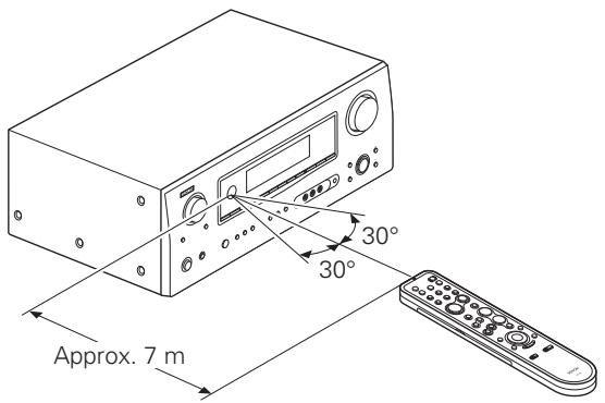
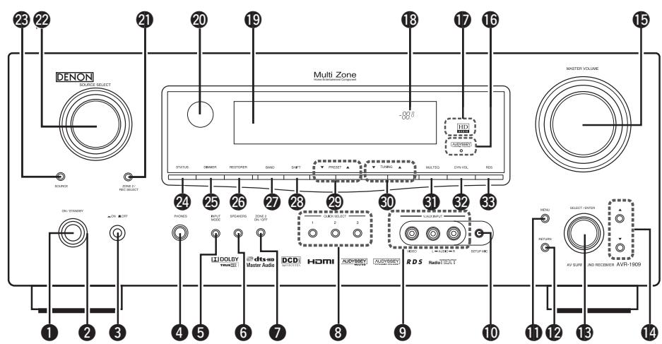
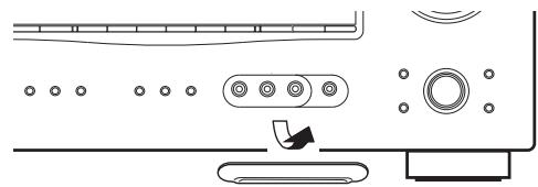


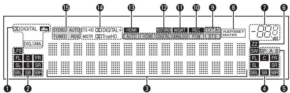
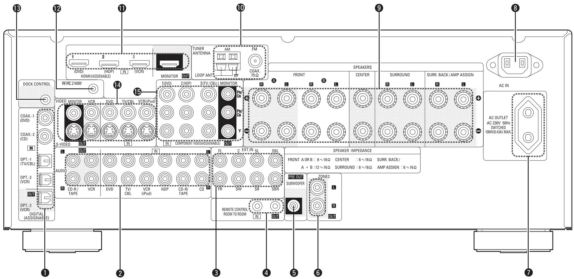
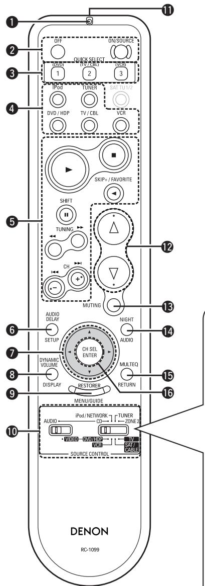
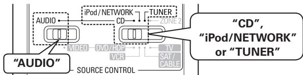
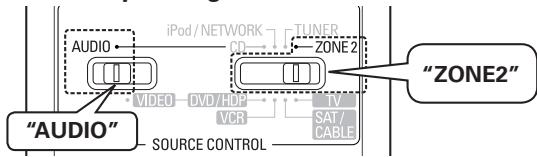
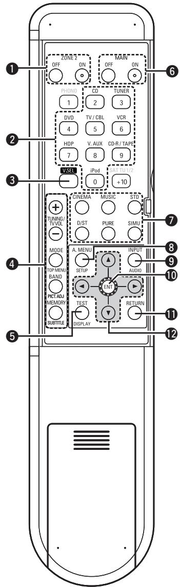


 [EDD] [SH80] [CHAT] [YYW0] [HOLZ] [OWT]Coaxial digital (75 Ω/ohms pin-plug) cableOptical digital connectionsOptical cableAnalog connections (stereo)(White) (Red) Stereo pin-plug cableAnalog connections (monaural, for subwoofer)(Black) Pin-plug cableSpeaker connections+ Speaker cables
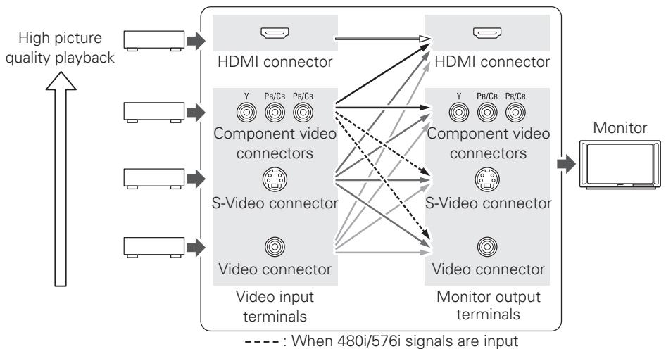

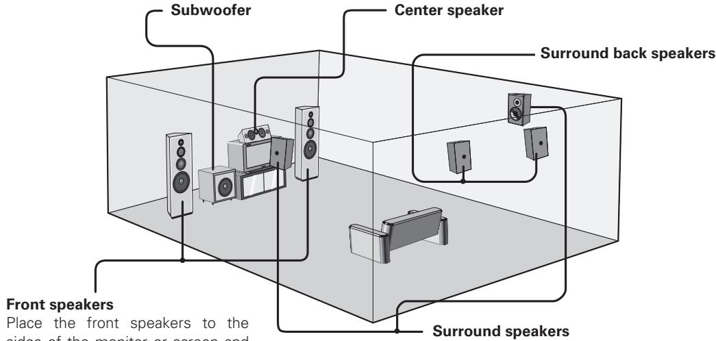


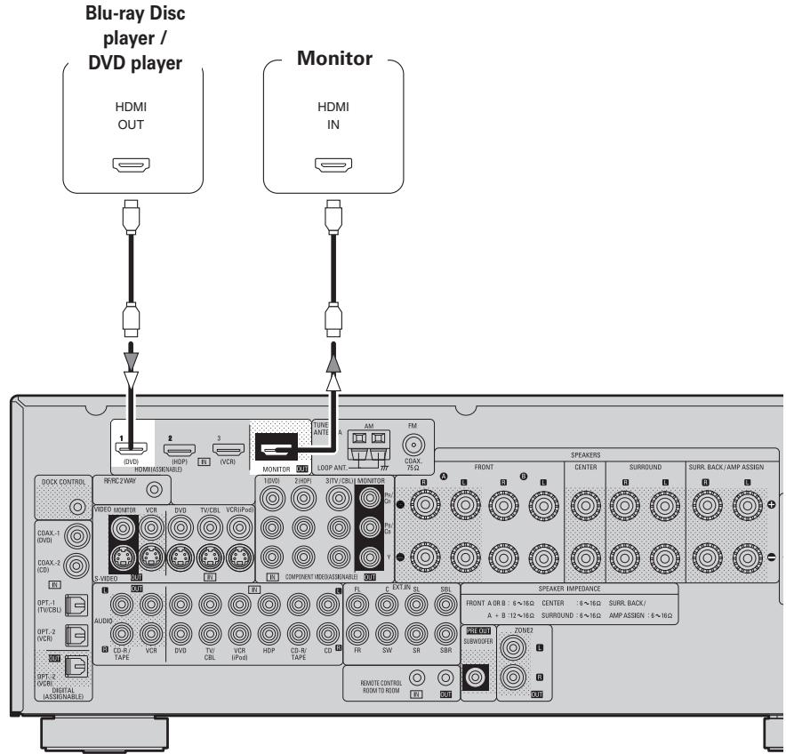


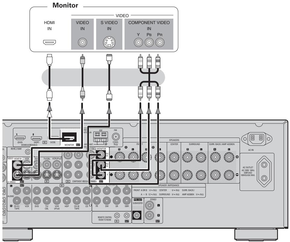


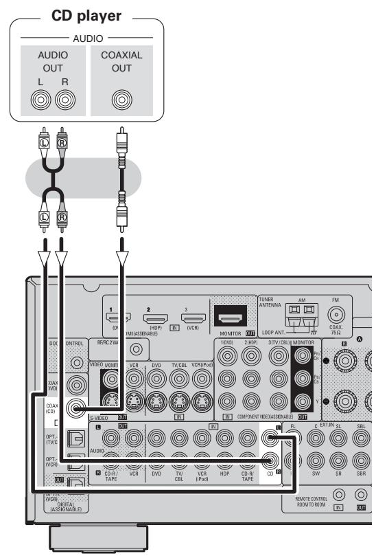
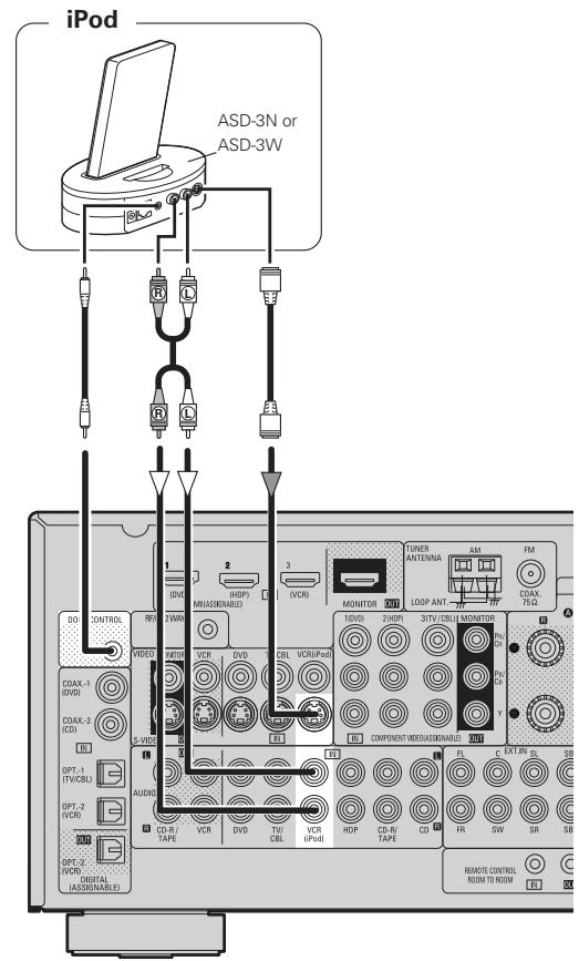
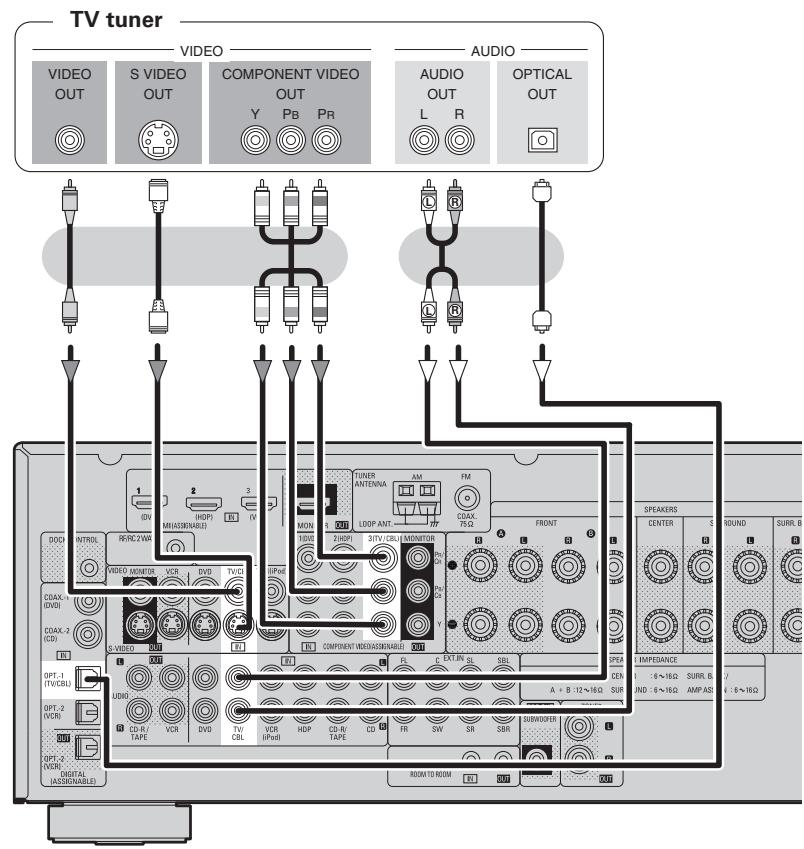


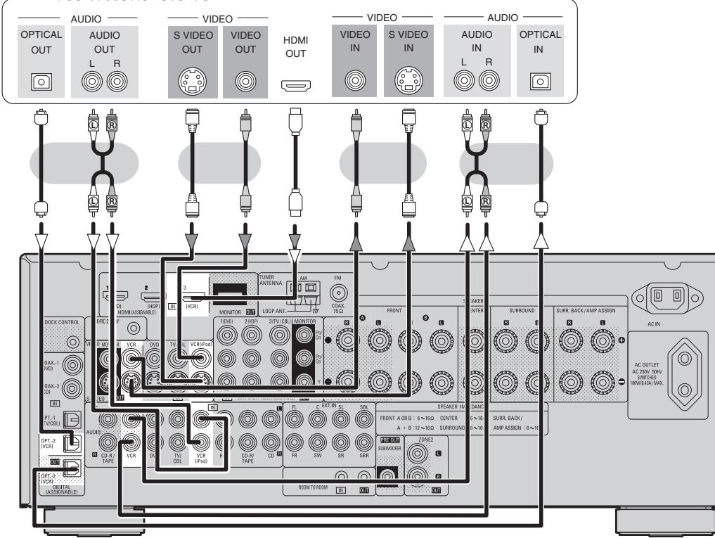

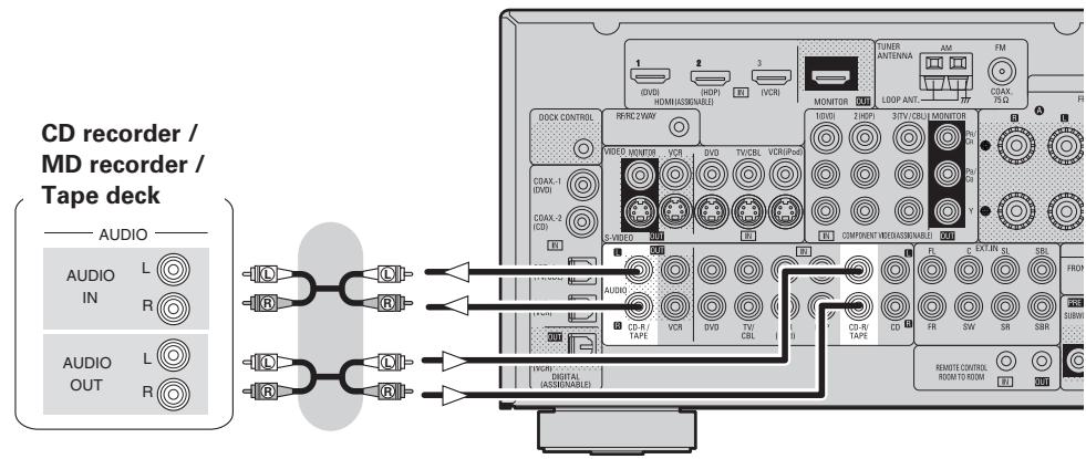
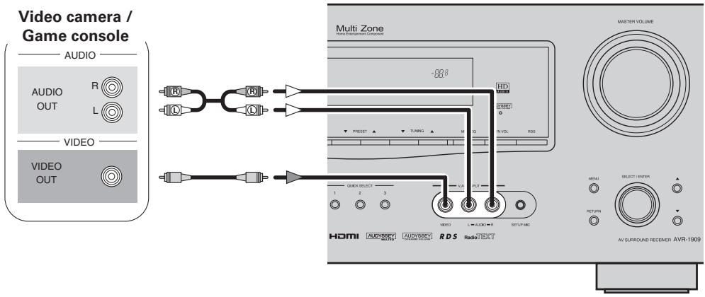
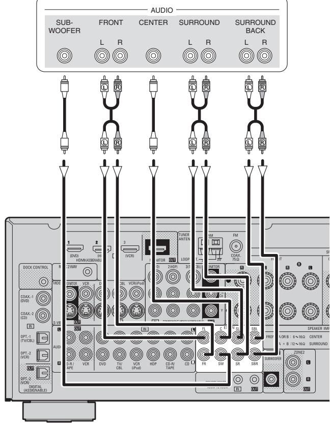


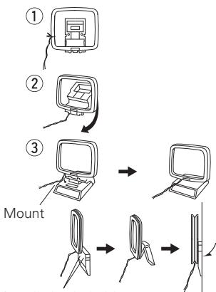

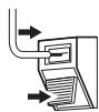

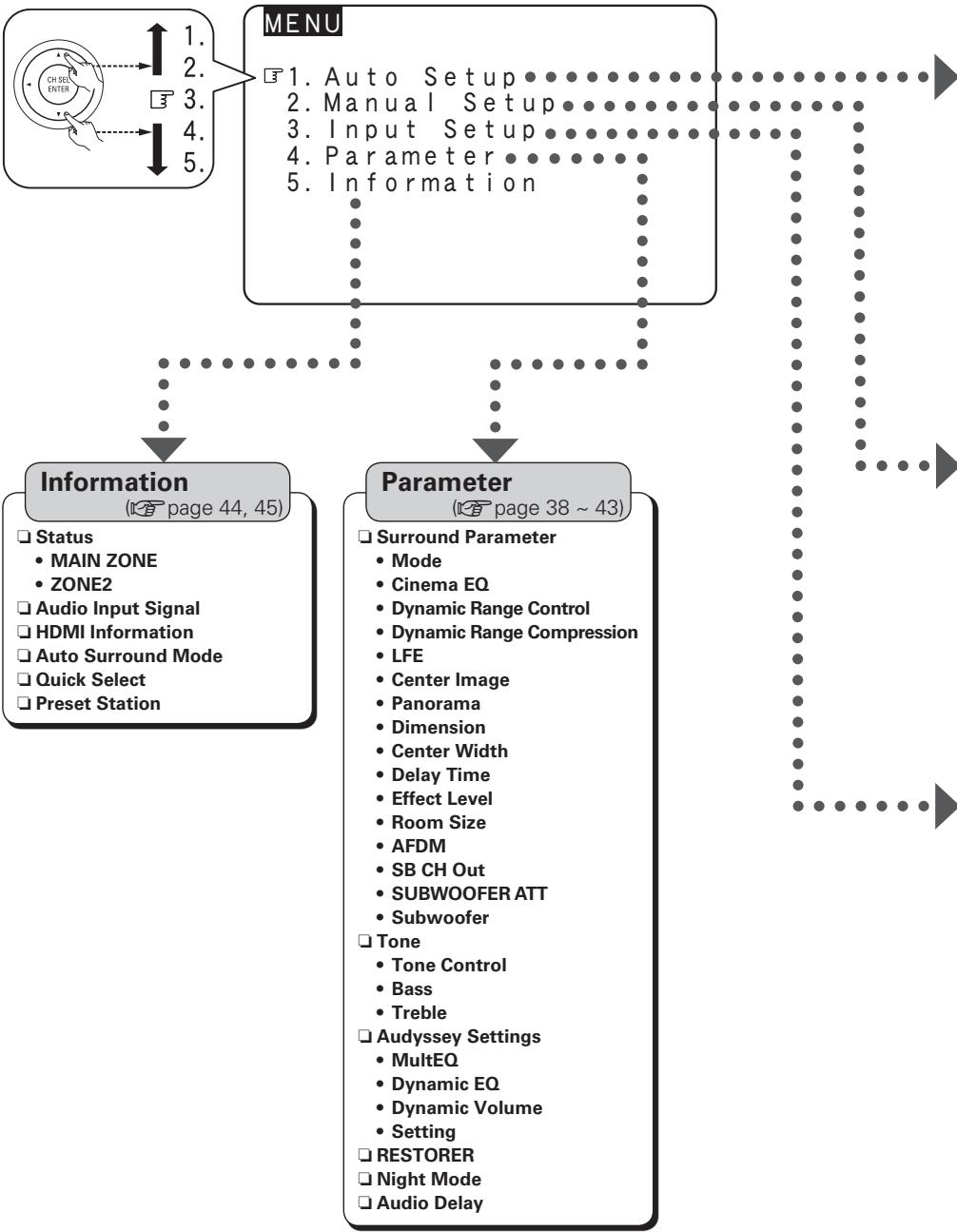

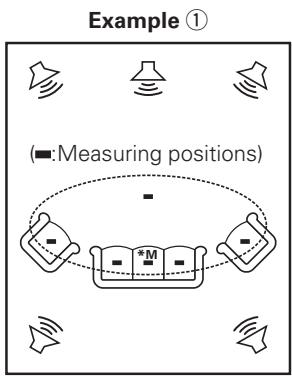
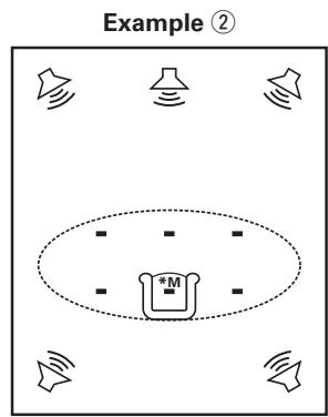

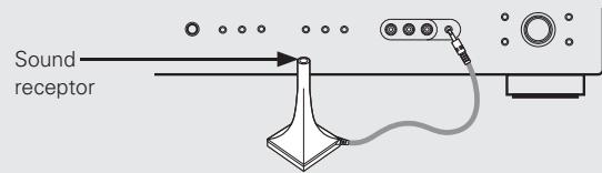
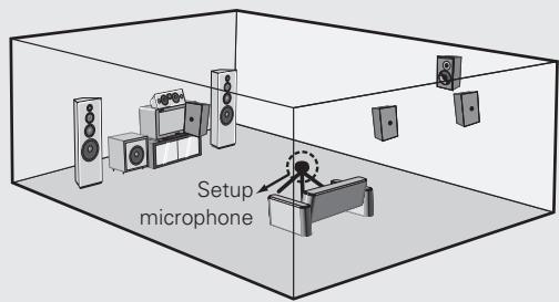


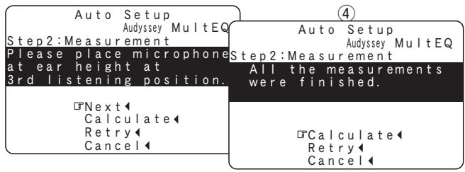


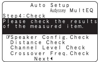

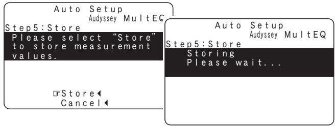
![DENON AVR-1909 - [Selectable items] - 1](/content/2025/01/135555/images/e42208b187672b1563753e56c52d4c7d0b84d25ccc10417cbdce1bf849c28803.jpg)

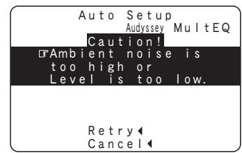
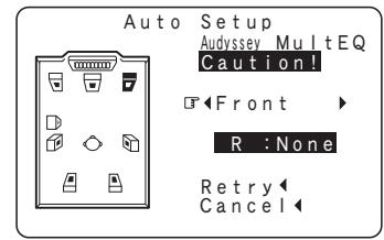


![SOURCE SELECT [A. MENU] [TEST]](/content/2025/01/135555/images/d456085cd108e74479868df3339141d9690a880b59b6d3cd29712398115b3785.jpg)

![DENON AVR-1909 - [Selectable items] - 1](/content/2025/01/135555/images/3b185a6227f2695b8c88c25d1b861bc816f29777403948a26d4e494066333d3e.jpg)


![DENON AVR-1909 - [Selectable items] - 1](/content/2025/01/135555/images/40fc090f6fffea3678c58e7d4a805a1ea5b6dc2c37e263b02e7dd79815083284.jpg)
![DENON AVR-1909 - [Selectable items] - 1](/content/2025/01/135555/images/487c2b7449027622b2dfa1628081d1c47b6c32e8e930fd0fb0629ae3f35763b9.jpg)

![DENON AVR-1909 - [Selectable items] - 1](/content/2025/01/135555/images/edcacdf7f3c531a1507f857b63bec95d102aa87e5ca358bccfc8908a4bd4c6db.jpg)


![DENON AVR-1909 - [Selectable items] - 1](/content/2025/01/135555/images/310f800404f07859846504c8dedffd4b62f95c1db7bfdc04b5524a049692c5c0.jpg)
![DENON AVR-1909 - [Selectable items] - 1](/content/2025/01/135555/images/1f785f6d97285390ffdf03661035e4809642808c950492cd38ba68263b757b08.jpg)
![DENON AVR-1909 - [Selectable items] - 1](/content/2025/01/135555/images/4daebdc06f702176f388318dfe7a1b702a1ac04d18c67e09af14111adeb5b60a.jpg)
![DENON AVR-1909 - [Selectable items] - 1](/content/2025/01/135555/images/f94c1e58e632d7e1b7af3af2ebeea8d120d6ce3009f2e2179ec4372f1b0f8320.jpg)

![DENON AVR-1909 - [Selectable items] - 1](/content/2025/01/135555/images/fab446a5df983725a16864da0786318d0ffd8f7ae3cd771b3b74a8340163600c.jpg)

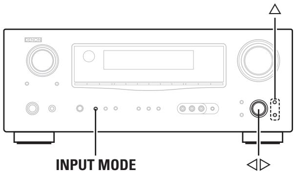
![[VIDEO SELECT] INPUT MODE](/content/2025/01/135555/images/ed3a58d56db07710ecdfa3f3a0abee5acbb93eaad3427ea3e56e02a54ddd3fd1.jpg)
![3. Input Setup VCR [VCR/iPod] 1. Assign 2. Video 3. Input Mode 4. Rename 5. Source Level 6. iPod 3-6. iPod Repeat Mode : All Shuffle Mode : OFF](/content/2025/01/135555/images/18a432a7da1d596144430c566ec4ab808b40d5b9dbfc2954be6478363714c01b.jpg)

![DENON AVR-1909 - [Selectable items] - 1](/content/2025/01/135555/images/7fa3276d9202748897ba31f231ffeb210afa752e155a3e76c1e916c2463177b1.jpg)
![DENON AVR-1909 - [Selectable items] - 1](/content/2025/01/135555/images/2188a7d9c1c045581d3ed2fc9e8ceadc30a6557aa4e250248ef7d67ec1f190c2.jpg)


![DENON AVR-1909 - [Selectable items] - 1](/content/2025/01/135555/images/b9214e5db6bb4d2b6ba104e91d64225836700114e1682230bd0222e96695b1ac.jpg)
![DENON AVR-1909 - [Selectable items] - 1](/content/2025/01/135555/images/f8be80853f711eb96eed0788bfa01faa21361564b62d06f9ac41f9cb68a9e4cd.jpg)
![DENON AVR-1909 - [Selectable items] - 1](/content/2025/01/135555/images/a1348654bec293a026c92ff9306a0a38f9f23328f9e5d55afa3ba6d367555b12.jpg)
![DENON AVR-1909 - [Selectable items] - 2](/content/2025/01/135555/images/40787f7efed8bc957a9ffd101a3ace8e8395179877d2bb8a3ccfa8b8ba29aa8e.jpg)
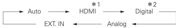
![DENON AVR-1909 - [Selectable items] - 1](/content/2025/01/135555/images/354c8b58d3c0d7c6815250a80415e0d2202b94250a569a39e8f998103e2bdb51.jpg)

![DENON AVR-1909 - [Selectable items] - 1](/content/2025/01/135555/images/7397b8946a861f11699c60ed29ec6a37238d4c1dc549d14290b6c40eb84a0e2c.jpg)
![DENON AVR-1909 - [Selectable items] - 1](/content/2025/01/135555/images/dd600d00e72a0fb1e66e2f171c73be435c4454be1f73039ca29d99394d472855.jpg)
![DENON AVR-1909 - [Selectable items] - 1](/content/2025/01/135555/images/8700c73ec5a73d42ccc7caa7841c99138f6f9c36b697afc607c6c6e5665f5c8d.jpg)

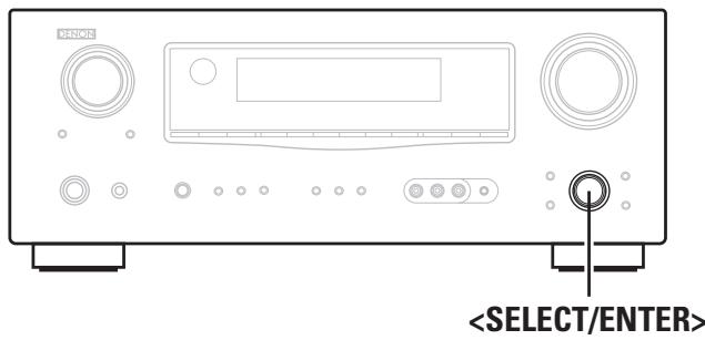
![[Rear] ZONE 3 OUT EN OFF MAIN SD/ PH (CH) CD TUNER 1 2 3 DVD TV / EBL VOR 4 5 6 HDF V-VALUE COM / TAPE 7 8 9 BEETER ON/OFF SAY TEST/12 0 IN IN IN IN IN IN IN IN IN IN IN IN IN IN IN IN IN IN IN IN IN IN IN IN IN IN IN IN IN IN IN IN IN IN IN IN IN IN IN IN IN IN IN IN IN IN IN IN IN IN OUT OUT OUT OUT OUT OUT OUT OUT OUT OUT OUT OUT OUT OUT OUT OUT OUT OUT OUT OUT OUT OUT OUT OUT OUT OUT OUT OUT OUT OUT OUT OUT OUT OUT OUT OUT OUT OUT OUT](/content/2025/01/135555/images/262cb3b043fd9b3ffbe9163dd1878e6d9162465883e82ada621796fb9dc21fcd.jpg)

![DENON AVR-1909 - [Selectable items] - 1](/content/2025/01/135555/images/fa8e54e72f7594b32b96ae3fa74fdd28c8b95b563697ee40fabda459cc404b36.jpg)


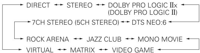
![DENON AVR-1909 - Press [PURE DIRECT]. - 1](/content/2025/01/135555/images/b8906e107f921c7b3998142f4120bbb1a06b1476ee818f1fa4840d5f7ecaaa15.jpg)

![[Front] [AUDIO DELAY] DYNAMIC VOLUME [SOURCE CONTROL 1] [NIGHT] △▽◀◀ ENTER MULTEQ RESTORER [Rear] [CINEMA] [A. MENU] [MUSIC] [STANDARD] ENTER △▽◀◀ RETURN](/content/2025/01/135555/images/b0111c764a21956388e033d7e02b7c3b5d58628d9d5c0978224ad91afe442424.jpg)
![DENON AVR-1909 - [Selectable items] - 1](/content/2025/01/135555/images/1e56369e911c3f566a35e8513655305f647187d1a5b3e35133d205fe7ce33452.jpg)


![DENON AVR-1909 - [Selectable items] - 1](/content/2025/01/135555/images/e3f7e94779e0968af010cafc81ba8c27ade9b7dc127372a9cd8871224196ee4a.jpg)


![DENON AVR-1909 - [Selectable items] - 1](/content/2025/01/135555/images/64f655794533a65439b71120fca77cf87cb4c9204ab276931eff0fb16cc22d2a.jpg)
![DENON AVR-1909 - [Selectable items] - 1](/content/2025/01/135555/images/dc135de1305f71c32e9bbda2d0ee18eb1055aded6b7798fb9db2e57b6985fdcb.jpg)
![DENON AVR-1909 - [Selectable items] - 1](/content/2025/01/135555/images/09e8e22f18c3b88fe4226e4b13334781c320becca10f5541a7b103272969757e.jpg)

![DENON AVR-1909 - [Selectable items] - 1](/content/2025/01/135555/images/55c4ab3327af6738b5af759e403c6cf0b90b1b230f1d01c5e06256f0649b4347.jpg)

![DENON AVR-1909 - [Selectable items] - 1](/content/2025/01/135555/images/1d26aab9fee424a412b190729c86fd5b401225c68703cedd2858ed208aaeb646.jpg)
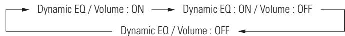

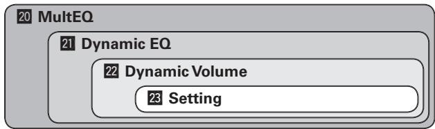
![DENON AVR-1909 - [Selectable items] - 1](/content/2025/01/135555/images/ad9ece66f33f2f5fac152dd6d2be223d7d64de8d08175f211516f6eddbcda3ec.jpg)
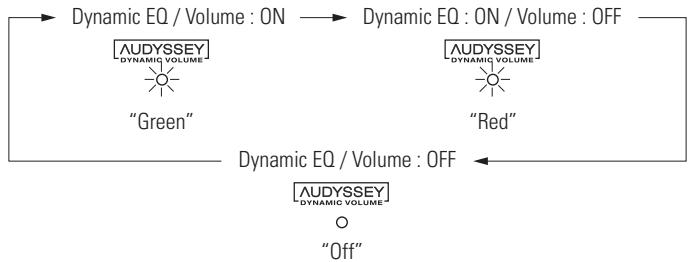

![DENON AVR-1909 - [Selectable items] - 1](/content/2025/01/135555/images/9c918bcf6012819a8428d42db8e51095813383fc76f8091992e6db34f3c5ef82.jpg)
![DENON AVR-1909 - [Selectable items] - 2](/content/2025/01/135555/images/340aa2b97ddda9484bc622e4146aed4b651c2ee8e57e9809948d7b38ffa3ace5.jpg)
![DENON AVR-1909 - [Selectable items] - 1](/content/2025/01/135555/images/b517842cf654793ed2a7c0c39174d7c621f9e7af9d8f1938b375aedc525ee75c.jpg)
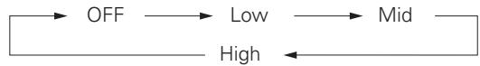


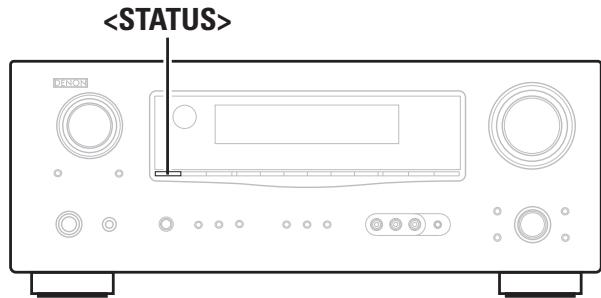


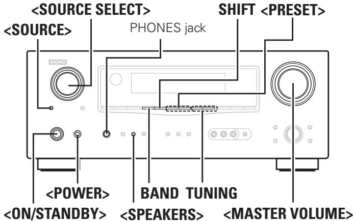
![[Front] [ON/SOURCE] [OFF] [QUICK SELECT] SOURCE SELECT [TUNER] SHIFT TUNING [MASTER VOLUME] [CHANNEL + -] [MUTING] [SOURCE CONTROL 1] [SOURCE CONTROL 2] [Rear] [TUNER] SOURCE SELECT TUNING [MODE] BAND [MEMORY]](/content/2025/01/135555/images/7612a77150aa40cec05603903c1a961812ef253ad11f2dab7e830f175cc5a4ed.jpg)

![DENON AVR-1909 - Press [MUTING]. - 1](/content/2025/01/135555/images/f38b8417f029cac8b3dd49182775a8b38d282da72c374c95276fc3b0b62106f0.jpg)


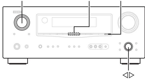
![SOURCE SELECT [TUNER] [CHANNEL + -] [SOURCE CONTROL 1] [SOURCE CONTROL 2] DENON RC-5009](/content/2025/01/135555/images/234ceb954dc67782beb9548afdebc6db230ad768176b6db4de6638c68eea6f3d.jpg)

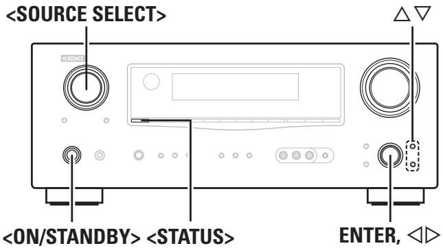
![[Front] [OFF] [iPod] [■] [▶] [◀◀, ▶▶] [I◀◀, ▶▶▶] △▽◀▶ ENTER [SOURCE CONTROL 1] [SOURCE CONTROL 2] DENON RGA1003 [Rear] [TUNING+ -] [MODE] △▽◀▶ ENTER](/content/2025/01/135555/images/7aa4bf99900f852831d1d3330104fb8adb8a4338de75d38b67b3329b0fc8d3f2.jpg)


![DENON AVR-1909 - Press [MODE] and hold it down for a 2 seconds or more to select the display mode. - 1](/content/2025/01/135555/images/b4bd5ba1e6e127046db1c4d426035b85290abbfeb1fb57ad70a041bf7109159f.jpg)


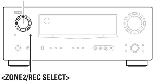
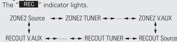


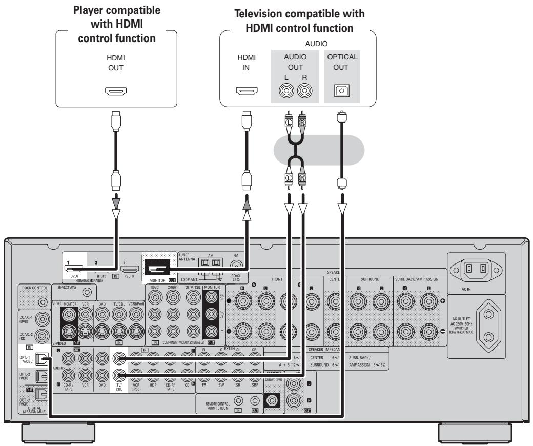

![[Front] QUICK SELECT [CH SELECT/ ENTER] [Rear] [CH SELECT/ ENTER]](/content/2025/01/135555/images/52fa9c2672bf2b08c53ddcdda93d6e01898b3fc3a3a4d6259dd22345e879ffa0.jpg)


![[SOURCE CONTROL 1] [SOURCE CONTROL 2] DENON AC-0093](/content/2025/01/135555/images/5158fa2baf83debc018e43e1976b2d9e441b106e94d61be1b858dc9389c7de9e.jpg)
![[ZONE2 OFF] [NUMBER] [MAIN ON]](/content/2025/01/135555/images/0fcaff2392307f3ca8ee324e3d212f09f17d3e0b1b6501a90135423b05d8e232.jpg)


![[OFF] [ON/SOURCE] [▶], [■], [SHIFT], [■], [◀], [SKIP + / FAVORITE], [TUNING], [◀◀ ▶▶▶], [I◀◀ ▶▶▶I], [CH + -] [SOURCE CONTROL 1] [SETUP], [△▽ ◀▶•] [AUDIO], [ENTER], [DISPLAY], [RETURN], [MENU/GUIDE] [SOURCE CONTROL 2] DENON RS-1000](/content/2025/01/135555/images/cd95c0fc22d32d32baf461f97b5c2c30526fd81066959b35a97d093826a42fb9.jpg)
![[NUMBER] (0~9, +10) [TUNING + -], [TV VOL + -], [MODE / TOP MENU], [BAND / PICTURE ADJUST], [MEMORY / SUBTITLE] [SETUP], [△▽◀▶], [AUDIO], [ENTER], [DISPLAY], [RETURN]](/content/2025/01/135555/images/b25761eca2067ac7d2a59e06c00708494db71a20bee53a08d5981e3e87439344.jpg)
![[Front] [▶], [■], [■], [◀], [◀◀▶▶], [I◀◀▶▶] [SOURCE CONTROL 1] [SOURCE CONTROL 2] DENON RC-1009](/content/2025/01/135555/images/91aca688831ad33c5380e302050aa4f481dda93920874f72c15617387939e4ab.jpg)
![[Rear] [NUMBER] [MEMORY] [RETURN]](/content/2025/01/135555/images/aafe6568195c9ad72f399ce6d404ae12ebe6755db49b8d7e0ca89c722dfbe1f8.jpg)


![[Front] [SOURCE SELECT] [VOLUME] [MUTING] [SOURCE CONTROL 2] [SOURCE CONTROL 1] DENON (R-109) [Rear] [ZONE2 OFF] [ZONE2 ON] [MAIN ON] [MAIN OFF] [SOURCE SELECT] With ZONE2, only the buttons indicated in this illustration can be operated. NOTE Buttons other than these cannot be operated.](/content/2025/01/135555/images/1d885fa52710809f75a08b04c3375a6ea235d219ef85caef659b5b7960a35192.jpg)
![DENON AVR-1909 - [Variable range] - 1](/content/2025/01/135555/images/de9487cf8780545d1a13b4621b94c1c3394018c487fdf9432c95b095d26021eb.jpg)
![DENON AVR-1909 - [Variable range] - 2](/content/2025/01/135555/images/337258bf0e0ce08ad7f4983e00afbfe2b91b15b47d8555ebb01cfff1b8bbb286.jpg)