
DRW-695 - CD and cassette player DENON - Free user manual and instructions
Find the device manual for free DRW-695 DENON in PDF.
| Product type | CD and cassette player |
| Brand | Denon |
| Model | DRW-695 |
| Dimensions (W x H x D) | 434 x 135 x 263 mm |
| Weight | 4.0 kg |
| Power supply | 50 Hz, voltage per label, power consumption 14 W |
| Noise reduction | Dolby B and C, Dolby HX-Pro |
| Playback functions | Relay playback, repeat (5 cycles), music search, memory stop |
| Recording functions | Synchronized recording, 2-speed dubbing, timer recording, pause, auto silence 5 s |
| Counters | Dual 4-digit tape counter with reset and memory |
| Settings | Bias fine (BIAS FINE), input level, automatic tape selection |
| Connections | Line input/output (RCA), headphone jack (8-1200 Ω), CD synchro jack |
| Remote control | Compatible with optional remote control (DRA series receiver) |
| Timer | Programmable recording and playback via external timer |
| Maintenance | Clean heads, pinch rollers, capstans with cotton swab and alcohol; regular demagnetization |
| Safety | 10 cm clearance around, avoid humidity/heat, unplug if not in use, do not block vents |
| Included accessories | Instruction manual, 2 connection cords, 1 mini-plug cable, list of authorized service centers |
| Repairability | Contact DENON dealer for technical assistance |
Frequently Asked Questions - DRW-695 DENON
User questions about DRW-695 DENON
0 question about this device. Answer the ones you know or ask your own.
Ask a new question about this device
Download the instructions for your CD and cassette player in PDF format for free! Find your manual DRW-695 - DENON and take your electronic device back in hand. On this page are published all the documents necessary for the use of your device. DRW-695 by DENON.
USER MANUAL DRW-695 DENON
STEREO CASSETTE TAPE DECK
DRW-695
OPERATING INSTRUCTIONS
BEDIENUNGSANLEITUNG
MODE D'EMPLOI
ISTRUZIONI PER L'USO
IMPORTANT TO SAFETY
WARNING:
TO PREVENT FIRE OR SHOCK HAZARD, DO NOT EXPOSE THIS APPLIANCE TO RAIN OR MOISTURE.
Please, record and retain the Model name and serial number of your set shown on the rating label.
Model No. DRW-695
Serial No.
CAUTION:
- The ventilation should not be impeded by covering the ventilation openings with items, such as newspapers, tablecloths, curtains, etc.
- No naked flame sources, such as lighted candles, should be placed on the apparatus.
- Please be care the environmental aspects of battery disposal.
- The apparatus shall not be exposed to dripping or splashing for use.
- No objects filled with liquids, such as vases, shall be placed on the apparatus.

CAUTION
RISK OF ELECTRIC SHOCK DO NOT OPEN

CAUTION:
TO REDUCE THE RISK OF ELECTRIC SHOCK, DO NOT REMOVE COVER (OR BACK). NO USER-SERVICEABLE PARTS INSIDE. REFER SERVICING TO QUALIFIED SERVICE PERSONNEL.

The lightning flash with arrowhead symbol, within an equilateral triangle, is intended to alert the user to the presence of uninsulated “dangerous voltage” within the product’s enclosure that may be of sufficient magnitude to constitute a risk of electric shock to persons.

The exclamation point within an equilateral triangle is intended to alert the user to the presence of important operating and maintenance (servicing) instructions in the literature accompanying the appliance.
• DECLARATION OF CONFORMITY
We declare under our sole responsibility that this product, to which this declaration relates, is in conformity with the following standards:
EN60065, EN55013, EN55020, EN61000-3-2 and EN61000-3-3.
Following the provisions of 73/23/EEC, 89/336/EEC and 93/68/EEC Directive.
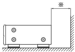
For heat dispersal, leave at least 10 cm of space between the top, back and sides of this unit and the wall or other components.
natural_image
Diagram of a CD or audio workstation with sound waves and control buttons, no text or symbols presentWall
Wand
Mur
Parete
Pared
Muur
Vägg
Parede
natural_image
Simple line drawing of a rectangular container with four circular holes and a vertical wall, no text or symbols present.NOTE ON USE / HINWEISE ZUM GEBRAUCH / OBSERVATIONS RELATIVES A L'UTILISATION / NOTE SULL'USO / NOTAS SOBRE EL USO / ALVORENS TE GEBRUIKEN / OBSERVERA / OBSERVAÇÕES QUANTO AO USO
natural_image
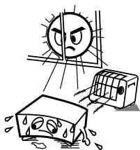
Illustration of a sunny weather scene with a sad face, a damaged airbag, and a distressed container (no text or symbols)- Avoid high temperatures.
Allow for sufficient heat dispersion when installed on a rack.
- Handle the power cord carefully.
Hold the plug when unplugging the cord.
natural_image
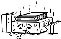
Cartoon illustration of a distressed rectangular object with falling raindrops, no text or symbols present- Keep the set free from moisture, water, and dust.
- Unplug the power cord when not using the set for long periods of time.
* (For sets with ventilation holes)
- Do not obstruct the ventilation holes.
- Do not let foreign objects in the set.
- Do not let insecticides, benzene, and thinner come in contact with the set.
- Never disassemble or modify the set in any way.
Thank you very much for purchasing the DENON component stereo cassette tape deck.
DENON proudly presents this advanced tape deck to audiophiles and music lovers as a further proof of DENON's non-compromising pursuit of the ultimate in sound quality. The high quality performance and easy operation are certain to provide you with many hours of outstanding listening pleasure.
— TABLE OF CONTENTS —
FEATURES 5
CONNECTION....5
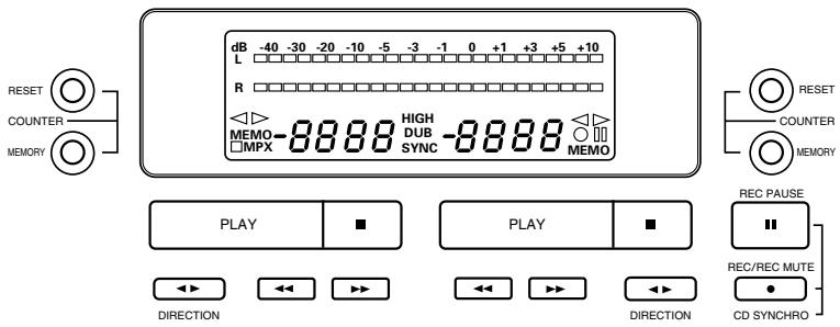
NAMES AND FUNCTIONS OF PARTS....6,7
CASSETTE TAPES 7
AUTOMATIC TAPE SELECTION ....7
PLAYBACK....8
RELAY PLAY 8
REC/REC MUTE AND REC PAUSE BUTTON 9
DIMMER ADJUSTMENT 9
DUBBING....10
SYNCHRONIZED RECORDING FUNCTION 10
TAPE COUNTER AND MEMORY STOP 11
Please check to make sure the following items are included with the main unit in the carton:
(1) Operating Instructions ....1
(2) Connection Cords ....2
(3) Mini-Plug Cable ....1
(4) Service Station List....1
FEATURES
■ Computer Controlled Mechanism
Dual Power Supply
■ Dolby HX-Pro Headroom Extension System
■ Dolby B & C Noise Reduction Systems
■ Manual Bias Adjustment Control
■ Dual Computing Tape Counter with 4-Digit Readout and Memory Stop
■ Music Search System
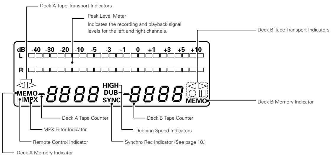
FL Peak Level Meters
■ Auto Tape Selector
2-Speed Dubbing
Relay Playback
■ Synchronized Recording
■ Timer Play and Timer Recording
■ Optional Remote Controllable
Tape Lighting
CONNECTION
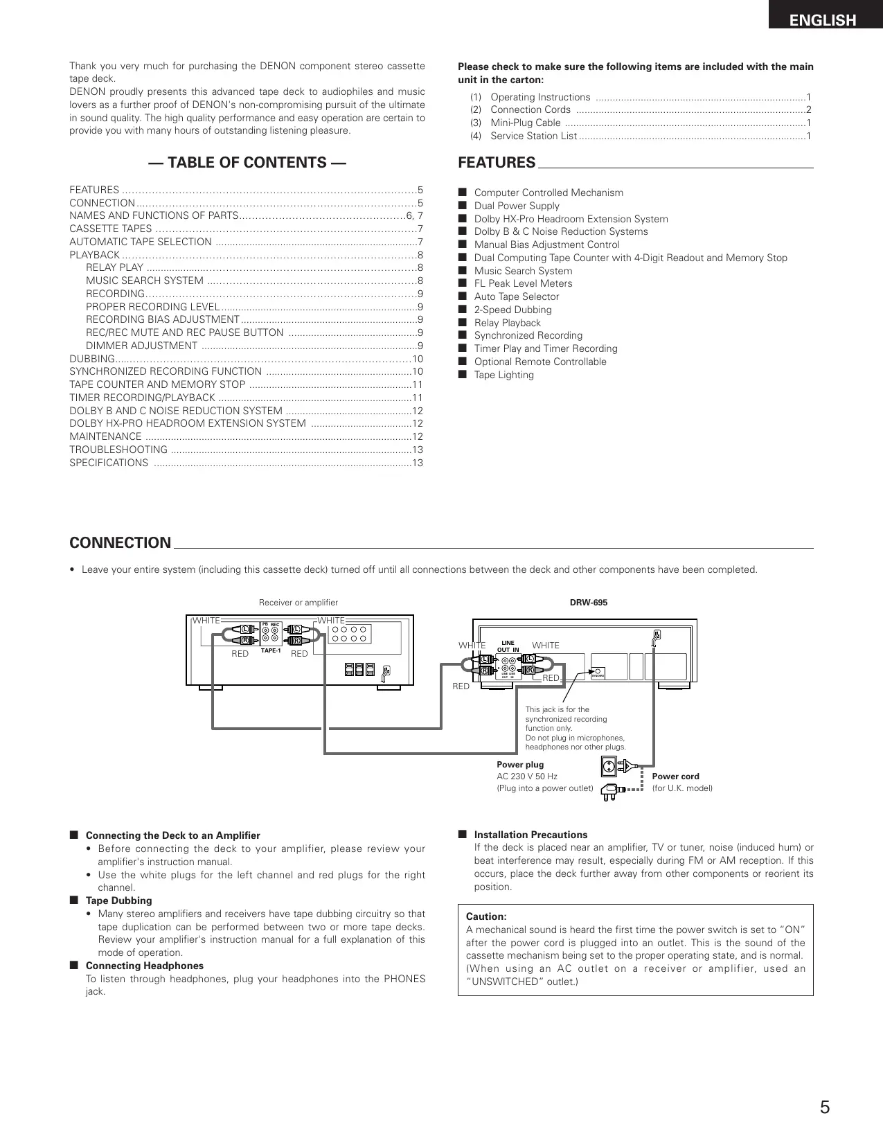
- Leave your entire system (including this cassette deck) turned off until all connections between the deck and other components have been completed.
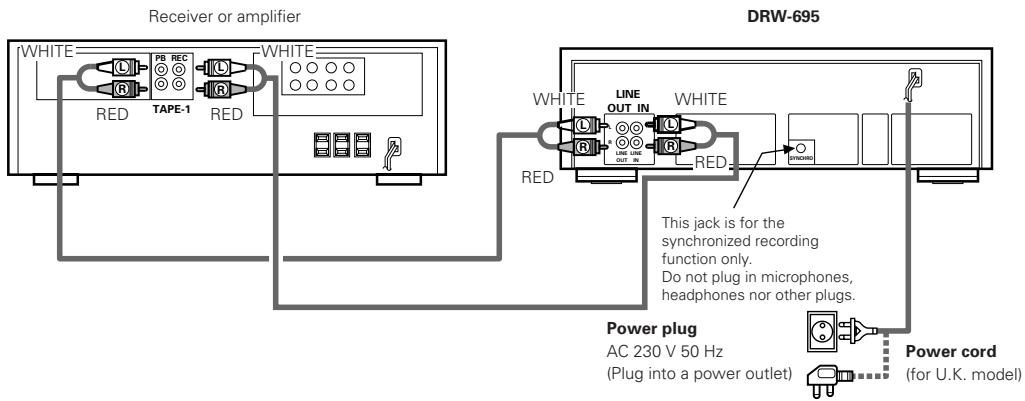
■ Connecting the Deck to an Amplifier
- Before connecting the deck to your amplifier, please review your amplifier's instruction manual.
- Use the white plugs for the left channel and red plugs for the right channel.
Tape Dubbing
- Many stereo amplifiers and receivers have tape dubbing circuitry so that tape duplication can be performed between two or more tape decks. Review your amplifier's instruction manual for a full explanation of this mode of operation.
■ Connecting Headphones
To listen through headphones, plug your headphones into the PHONES jack.
■ Installation Precautions
If the deck is placed near an amplifier, TV or tuner, noise (induced hum) or beat interference may result, especially during FM or AM reception. If this occurs, place the deck further away from other components or reorient its position.
Caution:
A mechanical sound is heard the first time the power switch is set to "ON" after the power cord is plugged into an outlet. This is the sound of the cassette mechanism being set to the proper operating state, and is normal. (When using an AC outlet on a receiver or amplifier, used an "UNSWITCHED" outlet.)
1 Power Operation Switch (ON STANDBY)
- Press this once to turn the cassette deck's power on. Press again to set the cassette deck to the standby mode.
- The deck remains in a stand-by (non-operative) mode for approximately 2 seconds after it is switched on.
Caution:
Whenever the Power Operation switch is in the STANDBY state, the apparatus is still connected on AC line voltage.
Please be sure to unplug the cord when you leave home for, say, a vacation.
② Eject Button ( ▲ )
- Press this button to open the cassette compartment cover. When the tape is running, press the STOP (■) button first to stop tape transport, then press the Eject button.
3 Counter Reset Button (COUNTER RESET)
- Press this button to reset the tape counter to zero.
4 MPX Filter Button (MPX)
- The MPX FILTER button should be used to prevent interference with the Dolby NR circuit when making Dolby NR encoded recordings of FM stereo programs.
- When making Dolby NR encoded recordings from any program source other than FM stereo, leave this button in the "OFF" position.
5 Counter Memory Button (MEMORY)
- When this button is pressed during forward tape travel ( ▷ ), fast rewinding ( ◀◀ ) will stop automatically at the tape counter position "......"
- When this button is pressed during reverse tape travel ( ◀ ), fast forwarding ( ▶ ) will stop automatically at the tape counter position " 0000". See page 11.
6 Dolby NR Switch (DOLBY NR)
- To record or playback tapes with Dolby B or C-type noise reduction, set this switch to "B" or "C". Turn it "OFF" when not using the Dolby NR system.
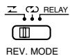
7 Reverse Mode Switch (REV. MODE)
- Select the type of tape transport. The reverse mode can be set to ☐ (one side), ☑ (continuous playback), RELAY (relay playback).
8 Dubbing Speed Buttons (DUBBING SPEED)
- Pressing the NORMAL button starts regular speed dubbing from deck A to deck B. Press the HIGH button to perform dubbing at double speed. See page 10.
9 Bias Fine Control (BIAS FINE)
(For Normal, CrO_2 and Metal tape)
- Use this control to fine-adjust the bias. Standard bias is obtained at the center click-stop position. See page 9.
10 Input Level Control (INPUT LEVEL)
- This knob adjusts the recording input level. It affects the level in both channels. See page 9.
11 Tape Lighting
- The tape lighting makes it possible to clearly check the amount of tape remaining.
12 Cassette Compartment Cover
- If the cover is not closed completely, the tape transport buttons will remain inoperative.
13 Headphone Jack (PHONES)
- For private music enjoyment without disturbing others, or for monitoring a recording, a headphone set may be connected to this jack. Use a headphone with an impedance rating of 8 to 1200 Ω/ohms.
14 Remote Sensor (REMOTE SENSOR)
- With DRW-695 the remote control unit is not included.
- Each of "PLAY, FF, REW, STOP, REC PAUSE and REC/REC MUTE" functions can be remote controlled with wireless handset of the receiver (DRA Series receivers). For details refer to the DRA Series operating instructions.
NOTE:
Note that only the A deck can be operated with remote control units which have no A/B selector button.
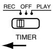
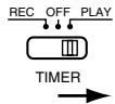
15 Timer Switch (TIMER)
- This switch is provided for use with an optional audio timer for unattended recording or morning-alarm playback.
- For non-timer operation, this switch should be set in the "OFF" position. See page 11.
16 Tape Transport Buttons
| PLAY | Play Button | Press to playback tape. |
| ■ | Stop Button | Press to stop the tape in any mode. |
| ◀◀ | Fast Rewind Button | Press for fast rewind. |
| ▶▶ | Fast Forward Button | Press for fast forwarding. |
| ●REC/REC MUTE(Deck B only) | Rec/Rec MuteButton | Press the REC/REC MUTE ( ● ) button and PLAY button simultaneously to start recording. If only the REC/REC MUTE ( ● ) button is pressed, the deck enters the Recording Pause mode. Pressing this button in the Recording Pause mode will start Auto Rec Mute, and a 5-second silent space is recorded onto the tape. See page 9. |
| ■RECPAUSE(Deck B only) | Rec Pause Button | Press this button to enter the recording pause mode from the recording or recording mute mode. This button can only be used during recording. See page 9. |
| ◀▶ | Direction Button | Changes the tape transport direction from forward “▶” to reverse “◀” and vice versa. |
CASSETTE TAPES
■ Handling Precautions
• C-120 and C-150 tapes
C-120 and C-150 cassette tapes use extremely thin tape that can easily get caught in the capstan or pinch roller. Do not use such cassette tapes.
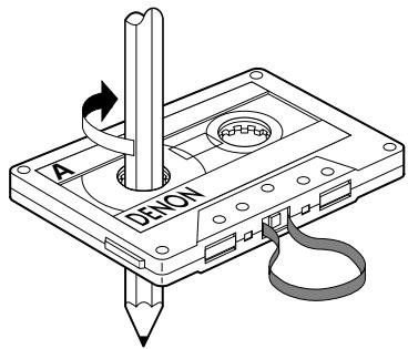
- Tape Slack
Before putting a tape into the deck, take up any slack with a pencil or your finger tip. This precaution prevents the tape from becoming entangled around the capstan or pinch roller.
■ Storage Precautions
- Do not store cassette tapes in a place where they will be subject to:
- Extremely high temperature or excessive moisture
- Excessive dust
- Direct sunlight
• Magnetic fields (near TV sets or speakers)
- To eliminate tape slack, store your cassettes in cassette cases with hub stops
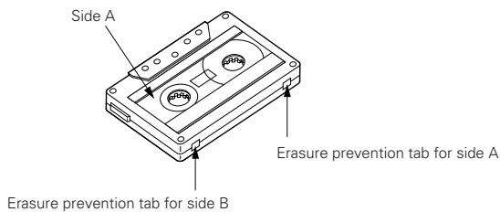
■ Accidental Erasure Prevention
- All cassettes have erasure prevention tabs for each side. To protect valuable recordings from accidental or inadvertent erasure, remove the tab for the appropriate side with a screwdriver or another tool.
- To record on a tape whose erasure prevention tabs have been removed, cover the tab holes with adhesive tape.
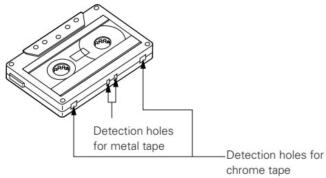
AUTOMATIC TAPE SELECTION
This Stereo Cassette Deck contains an automatic tape selector which automatically selects the optimum bias and equalization for the tape in use. This is accomplished by detection of the tape type detections holes in the cassette housing.
- If a tape without tape type detection holes is used, the deck will be set for normal tapes.
PLAYBACK
- The operations described below apply to deck A and deck B alike.
- Switch on your amplifier or receiver.
- Set the Tape Monitor switch on your amplifier or receiver to the TAPE position.
- The numbers in the illustration below depict the order in which operation steps are carried out.
① Press the POWER switch ① to the ON ( — ) position.
② Press the EJECT (▲) button ② to open the cassette compartment cover ⑫.
③ Load the cassette tape and close the cassette compartment cover 12.
④ When listening to a tape that has been recorded with Dolby noise reduction, set the DOLBY NR switch ⑥ to match the system used at the time of recording.
DOLBY NR
B OFF C
BOP
...
[Non-Text]
⑤ Press the Direction ( ◀▶ ) button 16 to select the direction of tape transport.
| Transport Direction | Indicator |
| Forward | |
| Reverse |
⑥ Select the type of tape transport with the REVERSE MODE switch 7.
Z C D RELAY
...
III
REV. MODE
| Mode | Switch position |
| To listen to one side only | |
| To listen to repeat playback of both sides | |
| To listen to continuous play back of both sides and both decks. | RELAY |
⑦ Press the PLAY button 16 to begin playback.
⑧ Press the stop ( ■ ) button 16 to stop the playback.
- In the continuous playback mode (REVERSE MODE set to 📄), playback of both tape sides will be repeated 5 times and then stop automatically.
- If different types of Dolby noise reduction are used for record and playback, playback response will be adversely effected.
- When power is turned off during tape transport, it may not be possible to remove the cassette by pressing the EJECT (▲) button. In this case, turn on power again before you press the EJECT (▲) button.
■ RELAY PLAY (continuous playback of the tapes in deck A and deck B)
- Load a cassette tape into deck A and B, and set the Dolby NR button correctly.
① REVERSE MODE set to "RELAY" 7.
② Press the PLAY button 16 of the deck you first wish to listen to.
③ To stop relay play, press the stop ( ■ ) button 16 of the deck currently playing the tape.
- Relay play will play decks A and B in succession for 5 cycles, upon which playback stops. When playback starts from deck B, when switching to deck A. the first deck A playback cycle will be counted as the second cycle. The completion of 5 cycles will always be at the opposite side of the tape in deck B.
The music search system detects blank sections (lasting for at least 4 seconds) between selections in order to locate the beginning of selections in the forward or reverse direction.
- To advance from the current selection to the beginning of the next selection (CUE):
Press the PLAY button, keep it pressed in, and press the Fast Forward (▶▶) button when the tape is travelling in the forward (▶) direction.
Press the PLAY button, keep it pressed in, and press the Fast Rewind (◀◀) button when the tape is travelling in the reverse (◀◀) direction.
The tape transport indicator flashes.
The deck will skip the rest of the current selection and automatically resume play from the beginning of the next selection.
- To repeat playback from the beginning of the current selection (REVIEW):
Press the PLAY button, keep it pressed in, and press the Fast Rewind (◀◀) button when the tape is travelling in the forward (▶) direction.
Press the PLAY button, keep it pressed in, and press the Fast Forward (▶▶) button when the tape is travelling in the reverse (◀) direction.
The tape transport indicator flashes.
The deck will rewind the tape to the beginning of the current selection and automatically resume play from that point.
This is very convenient for repeating playback of the current selection.
Notes on Music Search Operation:
The search functions operates by detecting comparatively long, blank sections approximately 4 to 5 seconds long, in between recorded selections. Therefore, the system may not operate normally in the following cases:
- Recordings with discontinuous speech or conversation.
- Recordings with long periods of pianissimo (softly played music).
• Recordings with long silences. - Blank sections with a high level of noise.
- Blank sections shorter than 4 seconds.
- If noise-emitting appliances, such as electric razors, drills, refrigerators, etc., are operated nearby.
- REV close to the beginning of the program or CUE close to the ending.
RECORDING (DECK B only)
- Switch on your amplifier or receiver and the source component.
- Set the Tape Monitor switch on your amplifier or receiver to the SOURCE position.
① Press the POWER switch ① to the ON ( — ) position.
② Load the cassette tape ②, ⑫.
(Check that the erasure prevention tabs of the cassette housing have not been broken off.)
③ Move the DOLBY NR switch ⑥ and select the Dolby NR type that suits the recording.

④ Press the Direction ( ◀▶ ) button 16 to select the direction of tape transport.
⑤ Select the type of tape transport with the REVERSE MODE button 7.
| Mode | Switch position |
| To record on only one side | |
| To continuously record on both sides | CD or RELAY |
⑥ Press the REC/REC MUTE (●) button 16 to set the recording pause mode. The ●■ indicator will light up.
⑦ Adjust the recording level with the INPUT LEVEL control 10 while watching the Peak Level Meter.
⑧ Press the PLAY button 16 to start the recording.
The PLAY ( ◀ or ▷ ) and the ● indicator will light during recording.
⑨ To pause the recording, press the REC PAUSE (Ⅲ) button 16, Press the PLAY button 16 to resume recording.
⑩ To stop recording, press the stop ( ■ ) button 16.
Caution:
- Be sure to press the stop (■) button to stop recording before turning off the power or unplugging the power supply cord.
-
Be careful not to erase important recordings by mistake. Inadvertent start of recording will happen in the following cases:
-
If the PLAY button is pressed while the ● indicator lights, recording starts.
- If the PLAY and REC/REC MUTE (●) button are pressed at the same time, recording starts.
The best way to avoid accidental erasure is to break off the two erasure prevention tabs on the cassette housing.
A too high recording level can saturate the tape and cause distortion. On the other hand, if the recording level is set too low, soft passages will be marked by residual noise. A proper recording level is the single most important factor for making well balanced recordings.
Guideline for maximum recording level
| TYPE I (Normal) | 0 dB level on peaks |
| TYPE II ( CrO_2 ) | +1 dB level on peaks |
| TYPE IV (Metal) | +3 dB level on peaks |
Note: The optimum recording level differs depending on the program source and the type of tape used.
■ RECORDING BIAS ADJUSTMENT
For best recording results, monitoring during recording and comparing different recordings using your own judgement are essential.
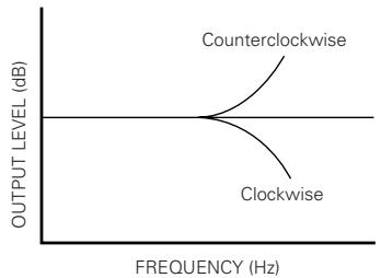
The DRW-695 is equipped with a BIAS FINE control to assist you in setting the proper bias for different types and brands of tape. At the center stop-click position, the deck is set to the reference bias level for Normal, CrO_2 and Metal tape. If the resulting recording in this position has too much or too little high frequency content, adjusting the BIAS FINE control can be useful to achieve better results.
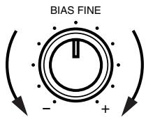
If the high frequencies (treble sounds) are to be boosted, turn the BIAS FINE control counter-clockwise to decrease the bias current. Turn the control clockwise to increase bias current.
By the use of this control, you can record tapes with a frequency response that will perfectly match your listening taste.
line
| FREQUENCY (Hz) | OUTPUT LEVEL (dB) | | -------------- | ----------------- | | Low | 0 | | Medium | High | | High | 0 |■ REC/REC MUTE AND REC PAUSE Button
- To record a 5-second blank section during recording:
Press the REC/REC MUTE (●) button. A 5-second blank will be recorded and the deck will enter the recording be standby mode.
- To record a 5-second blank section during the recording standby mode:
Press the REC/REC MUTE (●) button from the recording standby mode. A 5 second blank will be recorded and the deck will enter the recording standby mode again.
- To cancel recording of blank space:
Press the REC PAUSE (■) button. Blank space recording will be cancelled and the deck enters the recording standby mode.
- To extend the blank section with another 5 seconds or more:
Simply press the REC/REC MUTE (●) button and the blank section will be increased with another 5 seconds.
DIMMER ADJUSTMENT
With the DRW-695, the brightness of the display can be adjusted in seven steps.
To make the display brighter, press the B deck's fast forward (▶▶) button while holding in the B deck's STOP button.
To make the display dimmer, press the fast rewind (◀◀) button while holding in the STOP button.
The display is initially set to the maximum brightness.
DUBBING (from deck A to deck B)
- Switch on the amplifier or receiver.
- Set the Tape Monitor switch on your amplifier or receiver to the TAPE position.
① Press the POWER switch ① to the ON ( — ) position.
② Load the cassette tape to be played in deck A and the one to be recorded in deck B ②, ⑫.
③ Select the type of tape transport with the REVERSE MODE switch 7.
| Reverse mode | Operation |
| Dubbing is performed only for one side.The decks stop when either deck A or B reaches the end of the tape. | |
| The tape direction is reversed on each deck when they reach the end of the tape.(This is convenient for dubbing to a tape with a different length.) | |
| RELAY | During dubbing of the side facing you, the deck that first reaches the end of the tape will stand by until the other deck reaches the end of the tape, then both decks will reverse the tape direction together.(Depending on the manufacturer, the length of tapes having the same recording time may differ somewhat.Setting this mode permits the arrangement of the beginning portion of the opposite side of the tape.) |
④ To begin normal speed dubbing, press the DUBBING SPEED NORMAL button ⑧. The DUB indicator will light at this time.
To high speed dubbing, press the DUBBING SPEED HIGH button ⑧. The HIGH indicator will light at this time.
⑤ To stop dubbing, press the stop ( ■ ) button 16 of deck A or deck B.
- When deck A is in the playback mode and deck B is in the stop condition, setting deck B to the recording pause mode will engage the normal speed dubbing pause mode. Dubbing is then started by pressing the PLAY button.
- When dubbing, the recording level and the Dolby NR recording will be the same as those of the playback tape, regardless of the positions of the INPUT LEVEL control and the DOLBY NR button.
- When listening to the playback sound during normal speed dubbing, the DOLBY NR switch remains off even if it is pressed.
• The playback sound cannot be heard during high speed dubbing. - Operation using the REC/REC MUTE (●) and REC PAUSE (■) buttons of deck B is permitted during normal speed dubbing.
- Buttons other than the stop (■) button cannot be used during high speed dubbing.
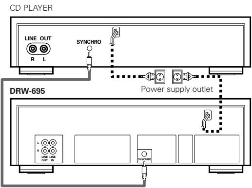
SYNCHRONIZED RECORDING FUNCTION
- Convenient synchronized recording can be performed when used in combination with a DENON CD player equipped for the synchronized recording function.
- SYNCHRO Jack Connection Connect the SYNCHRO Jack with a DENON CD player which is equipped with a SYNCHRO jack, then make a synchronized recording. Use the connection cord supplied with this cassette deck.
- Switch on your amplifier or receiver and the CD player.
- Set the tape Monitor switch on your amplifier or receiver to the source position.
① Load the tape onto which you want to record into deck B, the disc you want to record into the CD player.
② Following the recording instructions on page 9, set the Dolby NR mode, the direction, the reverse mode and the input level.
③ Set the CD player to the stop or pause mode.
④ Press the REC/REC MUTE (●) button and REC PAUSE (■) button simultaneously. The cassette deck and CD player are automatically set to the synchronized recording mode. The "SYNC" indicator lights on the cassette deck and the synchronized recording mode is indicated on the CD player.
(For details, refer to the CD player's operating instructions.)
⑤ To stop synchronized recording, press the stop button on deck B and stop button on CD.
The synchronized recording mode is cancelled for both the cassette deck and CD player.
⑥ To stop synchronized recording temporarily, press the stop button on the CD player. A 5-second blank space is created on the tape, after which the recording pause mode is set. The "SYNC" indicator flashes.
To resume synchronized recording, press the PLAY button on the CD player.
Notes:
- If synchronized recording is started when the CD player is in a mode other than the stop or pause mode or when no disc is set, the "SYNC" indicator on the cassette deck flashes and the recording pause mode is set until synchronized recording is possible on the CD player.
- In the synchronized recording mode, only the STOP button on deck B will function.
Caution:
- Do not set the cassette deck to the synchronized recording mode when the CD player is in the play mode. Also, do not turn off the power of the cassette deck or the CD player during synchronized recording. Doing so can result in malfunction.
- During the editing operation, when using the editing functions on the CD player, be sure to select a tape with a sufficiently long recording time.
For the CD player's editing functions, refer to the CD player's operating instructions.
TAPE COUNTER AND MEMORY STOP
1) Operation of the Tape Counter
(1) Press the RESET button to reset the counter to "0000".
(2) By using the PLAY, FF, or REW functions, the reading of the counter will change to indicate index position.
- During recording and playback operations, the counter is useful for noting the location of existing programs or positions where recording is to be started.
- The reading of this counter does not correspond with that of any other deck.
(3) Deck A and Deck B have the memory of their own counter.
2) MEMORY STOP Operation
(1) During recording or playback, the Memory Stop feature can be used to locate a particular point on the tape. Press the COUNTER RESET button at the desired point.
(2) Then Press the COUNTER MEMORY button, the MEMO indicator lights.
(3) When the Fast Rewind (◀◀) button is pressed during forward tape travel (▶), or the Fast Forward (▶▶) button is pressed during reverse tape travel (◀), the tape is rapidly rewound (or advanced) until the counter indication of “○○○○” is reached.
- The Memory Stop feature will rewind or forward the tape to within -5 counts in the forward ( ▶ ) direction (from " 0000 " to " -0005 ") and to within +5 counts in the reverse ( ◀ ) direction (from " 0000 " to " 0005"). After this, several seconds are required for corrective operations.
- The Memory Stop function operates independently in both directions for deck A and deck B.
Caution:
If the memory stop operation is performed after repeated fast-forwarding or rewinding, the tape may not stop at the proper position.
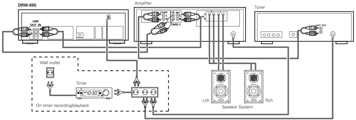
Timer recording/playback can be made using any audio timer available on the market.
flowchart
graph TD
    A["DRW-695"] --> B["Line OUT IN"]
    B --> C["ON/OFFICING"]
    C --> D["Amplifier"]
    D --> E["TUNER L"]
    D --> F["PB REC L"]
    D --> G["TAPE-1"]
    D --> H["SP"]
    D --> I["A"]
    D --> J["B"]
    D --> K["Lch"]
    D --> L["Speaker System"]
    D --> M["Rch"]
    N["Wall outlet"] --> O["Timer 10:30"]
    O --> P["On timer recording/ playback"]
    P --> Q["Speaker System"]
    R["Tuner"] --> S["OUT PUT"]
    T["Speaker System"] --> U["Rch"]
• Timer recording procedure
- Make sure the connections are correct, especially the power supply connections.
- Turn "on" the power switch of each appliance.
- Tune the desired station on the tuner.
- Load the tape for recording. (Make sure the erase prevention tab is not broken off; if it is, cover the hole with plastic tape).
- Set the Dolby NR switch to the appropriate position.
- Select the type of tape transport with the REVERSE MODE switch ⑦
- Make sure the monitor switch to the SOURCE position.
- Adjust the recording input level.
- Set the starting position of the tape.
- Set the timer switch (TIMER) to the "REC" side.
- Set the audio timer to the desired time. The audio timer will turn the power supply on at the desired time.
* With the above procedures, timer controlled recording can be made. When the preset time comes, the power is supplied and the FM broadcast can be recorded.
- Timer playback procedure
-
Make sure the connections are correct, especially the power supply connections.
-
Turn "on" the power switch of each appliance.
- Load the pre-recorded tape to be played back.
- Set the Dolby NR switches to the appropriate positions.
- Select the type of tape transport with the REVERSE MODE switch ⑦.
- Set the monitor switch of the Amplifier to the TAPE position.
- Press the PLAY (▶) button and playback the tape; adjust the playback level.
Press the stop ( ■ ) button.
- Set the timer switch (TIMER) to the "PLAY" side.
- Set the audio timer to the desired time. The audio timer will turn the power supply on at the desired time.
* With the above procedures, timer playback can be accomplished. When the preset time comes, the power is supplied and playback will start.
Notes:
- Please read the operating instructions for the timer before use.
- If the timer recording or playback is not desired, be sure to switch the timer switch (TIMER) to "OFF".
- When using timers that allow several “on/off” operations, timer start functioning can continue an unlimited number of times until the tape in the machine is finished.
DOLBY B AND C NOISE REDUCTION SYSTEM
The Dolby noise reduction system substantially reduces the tape background noise (hiss) inherent in the cassette medium. Dolby B NR is most widely in use. However Dolby C NR is a much more recent development and represents significant improvements over Dolby B NR.
Tape background noise consists primarily of high frequency information, which is particularly annoying during soft passages. The Dolby NR system increases the level of low volume mid- and high-frequency signals during recording and reduces the level of these signals by an identical amount during playback. As a result, the playback signal is identical to the original source, but the level of background noise generated by the tape is greatly reduced.
The operating principle of Dolby C NR is similar to that of Dolby B NR except for the encoding/decoding response curves. The noise reduction effect obtained with Dolby C NR is up to 20 dB, compared to 10 dB with Dolby B NR. In addition, Dolby C NR uses an anti-saturation network and spectral skewing circuitry for a significant improvement in the dynamic range of the mid- to high-frequencies.
This deck is equipped with the Dolby HX-PRO headroom extension system. Since the system functions automatically during recording, no switching operation or adjustment is required. The system is effective with any type of Normal, CrO_2 and Metal tape.
The Dolby HX-PRO headroom extension system functions during recording to raise the saturation level in the treble range. Therefore, most of the treble range components distorted or lost during recording on conventional cassette decks are more faithfully recorded on the new DENON cassette deck.
Features of the Dolby HX-PRO Headroom Extension System
(1) Performance of Normal and CrO_2 tapes can be improved to very close of that offered by Metal tape.
(2) The dynamics in the treble range are improved significantly.
(3) Since no decoding is necessary during playback, the improved sound can be enjoyed on any type of tape deck, including portable players and car audio systems.
(4) The system functions whether the Dolby B/C NR system is engaged or not.
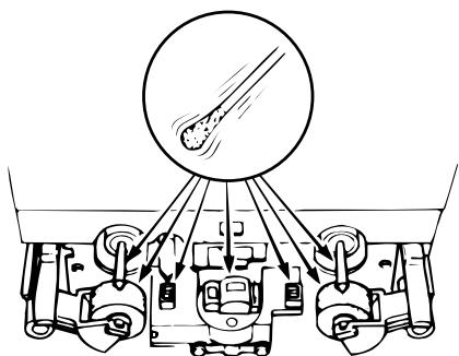
MAINTENANCE
Head Cleaning
After long usage, tape coating or dust may adhere to the heads, causing deterioration of sound. Therefore, the parts depicted in the illustration should be cleaned regularly. Use a cotton swab moistened with a tape head cleaning solution (such as alcohol).
Notes:
- Some cleaning cassettes on the market have strong abrasive effects and may scratch the heads. Always use cotton swabs instead of cleaning cassettes.
- Since the use of metal tape is apt to collect more dust on the heads, the heads should be cleaned more often to enjoy the best possible sound.
natural_image
Diagram of a vehicle's engine and suspension system with no visible text or symbols■ Cleaning the Pinch Rollers and Capstans
If the pinch rollers or capstans accumulate dust, tape transport may become unstable, as a result from slippage, during recording or playback. The tape can also be damaged if it gets entangled in the capstan. Clean these parts with a cotton swab or a soft cloth moistened with a tape head cleaning solution (such as alcohol).
■ Demagnetizing the Heads
The heads will become magnetized after long usage or if strongly magnetized objects are brought near them. The result is a generation of noise, loss of the high frequency range, and in extreme cases erasure of treble components on pre-recorded tapes in combination with added noise. Thus, the heads should be demagnetized at regular intervals. (Head demagnetizers are separately available from your dealer.)
■ How to Demagnetize the Tape Heads
- Turn off the power.
- Turn on the demagnetizer while it is at least 30 cm away from the heads. Bring the demagnetizer near the heads and slowly move it in small circles four or five times in front of each head, making sure you do not touch them.
- Slowly move the demagnetizer away and turn it off when it is at least 30 cm away from the heads.
Check the following before you draw the conclusion that your Stereo Cassette Deck is malfunctioning.
- Are all the connections correct?
- Are all system components being operated correctly in accordance with the operating instructions?
- Are the speakers and amplifier/receiver functioning correctly?
If the tape deck still does not function properly, check the symptom against the list below. If the symptom does not correspond to the check list, please contact your DENON dealer.
| Problem | Cause | Remedy |
| Tape does not run | Power cord is disconnected.Tape is loose.Cassette is not loaded properly.Defective cassette. | Check power cord.Tighten tape with a pencil, etc.Load cassette properly.Replace cassette. |
| Tape is not recorded when REC/REC MUTE (●) button is pressed. | No cassette is loaded.Erase prevention tabs are broken off. | Load cassette.Cover holes with adhesive tape. |
| Sound is warbled and distorted. | Heads, capstan or pinch roller are dirty.Tape is wound too tight.Recording input level is too high.Tape is worn out and has “drop-outs”. | Clean them.Fast forward or rewind to loosen tape winding.Adjust recording input level.Replace tape. |
| Excessive noise | Tape is worn Heads, capstan or pinch roller are dirty.Heads are magnetized.Recording input level is too low. | Replace them.Clean them.Demagnetize heads.Adjust recording input level. |
| High frequency range (treble) is emphasized. | Dolby NR switch is set improperly. | Set Dolby NR Switch properly. |
| High frequency range (treble) is lost. | Heads are dirty.Tape is worn. | Clean them.Replace tape. |
| The cassette tape cannot be removed. | If the POWER switch is turned off either during recording or playback and the unit is stopped, there may be cases when the cassette cannot be removed, even if the EJECT (▲) button is pressed. | Turn the POWER switch ON (■) again, and then press the STOP (■) button.Now, press the EJECT (▲) button to remove the cassette tape. |
SPECIFICATIONS
| Type | Vertical tape loading; 4-track 2-channel | Input | |
| stereo double cassette deck | LINE | 80 mV (-20 dBm) input level at maximum | |
| Heads | Play back head x 1 recording/playback head x 1 | Input impedance: 50 kΩ /kohms unbalanced | |
| Erase head (Double-gap ferrite) x 1 | Output | ||
| Motors | DC servo motor x 2 | LINE | 775 mV (0 dB) output level at maximum |
| Tape Speed | 4.8 cm/sec. | (with 47 kΩ /kohms load, recorded level of 200 pwb/mm) | |
| Fast Forward, Rewind Time | Approx. 110 sec. with a C-60 cassette | PHONES | 1.2 mW output level at maximum |
| Recording Bias | Approx 105 kHz | (optimum load impedance 8 Ω /ohms ~ 1.2 kΩ/kohms | |
| Overall S/N Ratio (at 3% THD level) | Dolby C NR on: more than 74 dB (CCIR/ARM) | Power Supply | 50 Hz, voltage is shown on rating label |
| Power Consumption | 14 W | ||
| Overall Frequency Response | 20 ~ 17,000 Hz ±3 dB (at -20 dB, Metal tape) | Dimensions | 434 (W) x 135 (H) x 263 (D) mm |
| Weight | 4.0 kg | ||
| Channel Separation | More than 40 dB (at 1 kHz) | ||
| Wow & Flutter | 0.08% WRMS, ±0.14% w. peak |
* Above specifications and design are subject to change without prior notice.
Manufactured under license from Dolby Laboratories.
HX Pro headroom extension originated by Bang and Olufsen.
"Dolby", "HX Pro", and the double-D symbol are trademarks of Dolby Laboratories.
natural_image
Diagram of a vehicle's engine suspension system showing wheel, suspension components, and exhaust pipe (no text or labels)CARACTERISTIQUES....23
CONNEXION 23
NOMENCLATURE ET FONCTIONS ......24, 25
BANDES CASSETTES 25
SELECTION AUTOMATIQUE DE BANDE 25
LECTURE....26
LECTURE RELAYEE 26
SYSTEME DE RECHERCHE MUSICALE 26
ENREGISTREMENT....27
NIVEAU D'ENREGISTREMENT APPROPRIE ......27
REGLAGE DE LA POLARISATION D'ENREGISTREMENT ......27
ENREGISTREMENT/ENREGISTREMENT SILENCIEUX
ET TOUCH DE PAUSE D'ENREGISTREMENT ......27
REGLAGE DU GRADATEUR D'INTENSITE D'ECLAIRAGE ....27
COPIE....28
FONCTION D'ENREGISTREMENT SYNCHRONISE ....28
COMPTEUR DE BANDE ET ARRET DE MEMOIRE ....29
ENREGISTREMENT/REPRODUCTION AVEC TEMPORISATEUR .....29
SYSTEME DE REDUCTION DE BRUIT DOLBY B ET C ....30
SYSTEME DE MARGE D'EXTENSION DOLBY HX-PRO ....30
ENTRETIEN ....30
DEPANNAGE 31
SPECIFICATIONS 31
line
| FREQUENCY (Hz) | NIVEAU DE SORTIE (dB) | | -------------- | -------------------- | | 0 | 0 | | 1 | 0 | | 2 | 0 | | 3 | 0 | | 4 | 0 | | 5 | 0 | | 6 | 0 | | 7 | 0 | | 8 | 0 | | 9 | 0 | | 10 | 0 | | 11 | 0 | | 12 | 0 | | 13 | 0 | | 14 | 0 | | 15 | 0 | | 16 | 0 | | 17 | 0 | | 18 | 0 | | 19 | 0 | | 20 | 0 | | 21 | 0 | | 22 | 0 | | 23 | 0 | | 24 | 0 | | 25 | 0 | | 26 | 0 | | 27 | 0 | | 28 | 0 | | 29 | 0 | | 30 | 0 | | 31 | 0 | | 32 | 0 | | 33 | 0 | | 34 | 0 | | 35 | 0 | | 36 | 0 | | 37 | 0 | | 38 | 0 | | 39 | 0 | | 40 | 0 | | 41 | 0 | | 42 | 0 | | 43 | 0 | | 44 | 0 | | 45 | 0 | | 46 | 0 | | 47 | 0 | | 48 | 0 | | 49 | 0 | | 50 | 0 | | 51 | 0 | | 52 | 0 | | 53 | 0 | | 54 | 0 | | 55 | 0 | | 56 | 0 | | 57 | 0 | | 58 | 0 | | 59 | 0 | | 60 | 0 | | 61 | 0 | | 62 | 0 | | 63 | 0 | | 64 | 0 | | 65 | 0 | | 66 | 0 | | 67 | 0 | | 68 | 0 | | 69 | 0 | | 70 | 0 | | 71 | 0 | | 72 | 0 | | 73 | 0 | | 74 | 0 | | 75 | 0 | | 76 | 0 | | 77 | 0 | | 78 | 0 | | 79 | 0 | | 80 | 0 | | 81 | 0 | | 82 | 0 | | 83 | 0 | | 84 | 0 | | 85 | 0 | | 86 | 0 | | 87 | 0 | | 88 | 0 | | 89 | 0 | | 90 | 0 | | 91 | 0 | | 92 | 0 | | 93 | 0 | | 94 | 0 | | 95 | 0 | | 96 | 0 | | 97 | 0 | | 98 | 0 | | 99 | 0 | | Note: The data is extracted from the code and presented in CSV format as requested. The 'Niveau de SORTIE' column contains zeros for the first three values. There is no additional data series in this case.■ ENREGISTREMENT/ENREGISTREMENT SILENCIEUX ET TOUCHE DE PAUSE D'ENREGISTREMENT (REC/REC MUTE ET REC PAUSE)
natural_image
Diagram of a vehicle suspension system with pulleys and a circular component (no text or labels)■ MUZIEKZOEKSYSTEEM (music search)
■ OPNAME-/OPNAMEDEMPING, OPNAME-PAUZE TOETS (REC/REC MUTE, REC PAUSE)
4 MPX filter-knapp (MPX)
14 Sensor remoto (REMOTE SENSOR)
- STEREO CASSETTE TAPE DECK
- DRW-695
- OPERATING INSTRUCTIONS
- BEDIENUNGSANLEITUNG
- MODE D'EMPLOI
- ISTRUZIONI PER L'USO
- IMPORTANT TO SAFETY
- WARNING:
- CAUTION:
- CAUTION
- • DECLARATION OF CONFORMITY
- NOTE ON USE / HINWEISE ZUM GEBRAUCH / OBSERVATIONS RELATIVES A L'UTILISATION / NOTE SULL'USO / NOTAS SOBRE EL USO / ALVORENS TE GEBRUIKEN / OBSERVERA / OBSERVAÇÕES QUANTO AO USO
- — TABLE OF CONTENTS —
- Please check to make sure the following items are included with the main unit in the carton:
- FEATURES
- CONNECTION
- ■ Connecting the Deck to an Amplifier
- Tape Dubbing
- ■ Connecting Headphones
- ■ Installation Precautions
- Power Operation Switch (ON STANDBY)
- ② Eject Button ( ▲ )
- Counter Reset Button (COUNTER RESET)
- MPX Filter Button (MPX)
- Counter Memory Button (MEMORY)
- Dolby NR Switch (DOLBY NR)
- Reverse Mode Switch (REV. MODE)
- Dubbing Speed Buttons (DUBBING SPEED)
- Bias Fine Control (BIAS FINE)
- Input Level Control (INPUT LEVEL)
- Tape Lighting
- Cassette Compartment Cover
- Headphone Jack (PHONES)
- Remote Sensor (REMOTE SENSOR)
- NOTE:
- Timer Switch (TIMER)
- CASSETTE TAPES
- ■ Handling Precautions
- • C-120 and C-150 tapes
- - Tape Slack
- ■ Storage Precautions
- ■ Accidental Erasure Prevention
- AUTOMATIC TAPE SELECTION
- PLAYBACK
- ■ RELAY PLAY (continuous playback of the tapes in deck A and deck B)
- Notes on Music Search Operation:
- RECORDING (DECK B only)
- ■ RECORDING BIAS ADJUSTMENT
- ■ REC/REC MUTE AND REC PAUSE Button
- DIMMER ADJUSTMENT
- DUBBING (from deck A to deck B)
- SYNCHRONIZED RECORDING FUNCTION
- Notes:
- TAPE COUNTER AND MEMORY STOP
- 1) Operation of the Tape Counter
- 2) MEMORY STOP Operation
- • Timer recording procedure
- - Timer playback procedure
- DOLBY B AND C NOISE REDUCTION SYSTEM
- Features of the Dolby HX-PRO Headroom Extension System
- MAINTENANCE
- Head Cleaning
- ■ Cleaning the Pinch Rollers and Capstans
- ■ Demagnetizing the Heads
- ■ How to Demagnetize the Tape Heads
- Check the following before you draw the conclusion that your Stereo Cassette Deck is malfunctioning.
- ■ ENREGISTREMENT/ENREGISTREMENT SILENCIEUX ET TOUCHE DE PAUSE D'ENREGISTREMENT (REC/REC MUTE ET REC PAUSE)
- ■ MUZIEKZOEKSYSTEEM (music search)
- ■ OPNAME-/OPNAMEDEMPING, OPNAME-PAUZE TOETS (REC/REC MUTE, REC PAUSE)
- MPX filter-knapp (MPX)
- Sensor remoto (REMOTE SENSOR)
Brand : DENON
Model : DRW-695
Category : CD and cassette player