SEKU 2000 A1 - Fireplace SILVERCREST - Free user manual and instructions
Find the device manual for free SEKU 2000 A1 SILVERCREST in PDF.


| Product Type | Electric Fireplace |
| Brand | SilverCrest |
| Model | SEKU 2000 A1 |
| Dimensions (W x H x D) | 60 cm x 45 cm x 15 cm |
| Weight | 5 kg |
| Power Supply | 220-240 V, 50 Hz |
| Power Consumption | 2000 W |
| Heat Output | 2000 W (adjustable) |
| Heating Area | Up to 25 m² |
| Thermostat | Adjustable thermostat (5-35 °C) |
| Flame Effect | LED flame effect with or without heat |
| Remote Control | Included |
| Timer | 1-8 hours |
| Safety Features | Overheat protection, tip-over switch |
| Noise Level | < 40 dB (fan only) |
| Installation | Freestanding or wall-mounted |
| Maintenance | Clean with soft damp cloth; remove dust from vents |
| Spare Parts | Available via SilverCrest service |
| Repair Index | 6.5/10 (estimated) |
| Warranty | 3 years |
Frequently Asked Questions - SEKU 2000 A1 SILVERCREST
User questions about SEKU 2000 A1 SILVERCREST
0 question about this device. Answer the ones you know or ask your own.
Ask a new question about this device
Download the instructions for your Fireplace in PDF format for free! Find your manual SEKU 2000 A1 - SILVERCREST and take your electronic device back in hand. On this page are published all the documents necessary for the use of your device. SEKU 2000 A1 by SILVERCREST.
USER MANUAL SEKU 2000 A1 SILVERCREST
GB Electric Fireplace Operating instructions
Information for these operating instructions .....2
Copyright 2
Limited liability 2
Warnings 3
Intended use 3
Safety 4
Risk of electrocution ....4
Basic Safety Instructions ....4
Setting up and connecting ..... 5
Safety Notices ....5
Items supplied and delivery checks .....5
Disposal of the packaging ....5
Installation requirements....6
Before the first use 6
Electrical connection....6
Operating components ..... 7
Set up 8
Individual parts of the electric fi replace .....8
Screws and assembly material 9
Assembly 10
Handling and operation ..... 15
Switching the appliance on and off .....15
Maintenance 15
Changing the light bulbs....15
Cleaning 16
Troubleshooting 16
Malfunction causes and remedies .....17
Storage/Disposal 17
Storage....17
Disposal of the appliance ....17
Appendix 18
Technical data....18
Notes on the EC Declaration of Conformity ....18
Warranty 19
Service....19
Importer 19
GB
Introduction
Information for these operating instructions
These operating instructions are a component of the SEKU 2000 A1 Electric Fireplace (henceforth designated as the appliance) and they provide you with important information about the intended use, safety, installation and connection as well as operation of the appliance.
These operating instructions must at all times be kept available close to the appliance. They are to be read and applied by everyone assigned to install, service and repair faults in the appliance.
Keep these operating instructions and hand them over with the appliance to any future owners.
Copyright
This documentation is copyright protected.
Any copying or reproduction of this handbook, including extracts, as well as the rendering of any images, even in an altered state, is permitted only with the written consent of the manufacturer.
Limited liability
All technical information, data and instructions for installation, connection and operation contained in these operating instructions correspond to the status at the time of printing and, to the best of our knowledge, take into account our previous experience and know-how.
No claims can be derived from the details, illustrations and descriptions in these instructions.
The manufacturer assumes no liability for damage caused by failure to observe these instructions, improper use, inappropriate repairs, making unauthorized modifications or for using unapproved replacement parts.
Warnings
In these operating instructions the following warnings are used:

DANGER
A warning at this danger level indicates a threateningly dangerous situation.
If the dangerous situation is not avoided, it could result in death or serious injury.
- Compliance with the instructions in this warning is necessary to avoid the risk of death or serious injury.

WARNING
A warning at this danger level indicates a potentially dangerous situation.
If the dangerous situation is not avoided it can lead to injuries.
The directives in this warning are there to avoid personal injuries.
IMPORTANT
A warning of this danger level signifies possible property damage.
If the situation is not avoided it can lead to property damage.
The directives in this warning are there to avoid property damage.
NOTICE
▶ A notice signifies additional information that assists in the handling of the appliance.
Intended use
This appliance is intended for the heating of enclosed living spaces. In addition, artificial fi re fl ares can be created with the appliance to optically replicate an open-hearth fi re.
This appliance is not intended for any other use or for uses other than those mentioned.

WARNING
Risks from unintended use!
Risks can be created by the appliance if it used for unintended purposes and/or for other applications.
▶ Use the appliance exclusively for its intended purposes.
Observe the procedures described in these operating instructions.
Claims of any kind for damage resulting from unintended use will not be accepted.
The operator alone bears the liability.
Safety
In this chapter you are being given important safety information regarding the handling of the appliance.
This appliance complies with the statutory safety regulations. Incorrect usage can, however, lead to personal and property damage.

Do not cover the appliance!
Covering the appliance can cause overheating and thus lead to the development of a fire!
Risk of electrocution
DANGER
Risk of electrocution!
A potentially fatal situation can arise from contact with live wires or components!
Pay heed to the following precautions to avoid the risk of electric shock:
- Do not use the appliance if the mains power plug or the connecting cable are damaged.
Before continuing to use the appliance, arrange for the connecting cable to be replaced by authorised qualified persons. - Do not, under any circumstances, open the appliance housing. There is the risk of receiving an electric shock if the power carrying connections are touched and/or the electrical and mechanical construction is changed.
Basic Safety Instructions
For safe handling of the appliance observe the following safety information:
■ Before use check the appliance for visible external damage. Do not put into operation a appliance that is damaged or has been dropped.
- Arrange for damaged cables or connections to be replaced by authorized qualified persons or by the Customer Service department.
This appliance is not intended for use by individuals (including children) with restricted physical, physiological or intellectual abilities or deficiencies in experience and/or knowledge unless they are supervised by a person responsible for their safety or receive from this person instruction in how the appliance is to be used.
■ Children should be supervised to ensure that they do not play with the appliance.
■ Repairs should only be carried out by authorized specialist companies or by the customer service department. Incorrect repairs can result in significant dangers for the user. In addition warranty claims become void.
During the warranty period repairs to the appliance may only be carried out by a Customer Service department authorised by the manufacturer, if they are not, no additional warranty claims can be considered for subsequent damages.
■ Defective components may only be replaced with original replacement parts. Only by using original replacement parts can it be guaranteed that the safety requirements are being complied with.
Protect the appliance from moisture and liquid penetration. ■
The appliance may not be used directly adjacent to a bath-tub, shower or swimming pool.
■ Always pull on the plug when disconnecting from the mains power socket, never pull on the connection cable.
Do not use the appliance adjacent to open flames.
The appliance may not be located directly below a mains power socket.
■ If malfunctions occur or thunder storms threaten, remove the plug from the mains power socket.
■ Never subject the appliance to spray and/or dripwater, do not place any objects filled with liquid (i.e. vases), or filled drink glasses, on or next to the appliance.
This appliance may not be used with a programme switch, a timer switch, a separate remote control system or any other device that switches the appliance on automatically, as there will be a risk of fire if the appliance is covered or positioned incorrectly.
Setting up and connecting
Safety Notices
WARNING
During commissioning of the appliance, damage may occur to persons and property!
Pay heed to the following safety information to avoid these risks:
▶ Packaging material should not be used as a play thing. There is a risk of suffocation.
- Comply with the notices in regard to the requirements for the installation site and for the electrical connection to avoid risks for people and property.
Items supplied and delivery checks
The appliance is delivered with the following components as standard:
Electric Fireplace
Lightbulbs, 2 x E14, max. 25 W (preinstalled)
Fireplace panelling including assembly material
Operating instructions
NOTICE
▶ Check the contents to make sure everything is there and for visible damage.
If the contents are incomplete, or are damaged due to defective packaging or transportation, contact the Service Hotline (see warranty card).
Disposal of the packaging

The packaging protects the appliance from transport damage. The packaging materials are selected from the point of view of their environmental friendliness and disposal technology and are therefore recyclable.
The recirculation of packaging into the material circuit saves on raw material and reduces generated waste. Dispose of packaging material that is no longer needed according to the regionally established regulations.
NOTICE
If possible preserve the appliance's original packaging during the warranty period so that in the case of a warranty claim you can package the appliance properly for return.
Installation requirements
For the safe and correct operation of the appliance, the installation site must satisfy the following requirements:
■ The appliance must be placed on a fi rm, fl at and horizontal surface.
- Do not place the appliance in a hot, wet or very humid environment or close to inflammable materials. The appliance may not be used directly adjacent to a bath-tub, shower or swimming pool.
The mains power socket must be easily accessible at all times, thus enabling the plug to be immediately withdrawn should an emergency situation arise.
■ The appliance may not be located directly below a mains power socket.
Ambient temperature range: +5 to +45 °C
Humidity (No condensation): 5 - 90 %

DANGER
Fire hazard due to material contact!
If the heater makes contact with flammable materials, there is a risk of fire!
Pay heed to the following safety information to avoid these fire risks:
- Keep infl ammable materials well away from the place of installation of the appliance.
▶ Prevent the physical contact of combustible materials (e.g. textiles) with the appliance.
Do not cover the warm air outlet openings of the appliance.
Before the first use
Remove all packaging materials and transport restraints from the appliance.
NOTICE
- When you first use it, it may temporarily generate a light odour. This is normal and completely harmless.
Electrical connection
For a safe and correct operation of the appliance, take note of the following instructions regarding the electrical connection:
Before you connect the appliance, compare the connection data (voltage and frequency) on the plate with that of your electricity supplier. This data must tally, in order to avoid damage to the appliance.
■ Ensure that the power cable is undamaged and that it is not placed over hot surfaces and/or sharp edges.
The connecting cable must not be taut.
Operating components
NOTICE
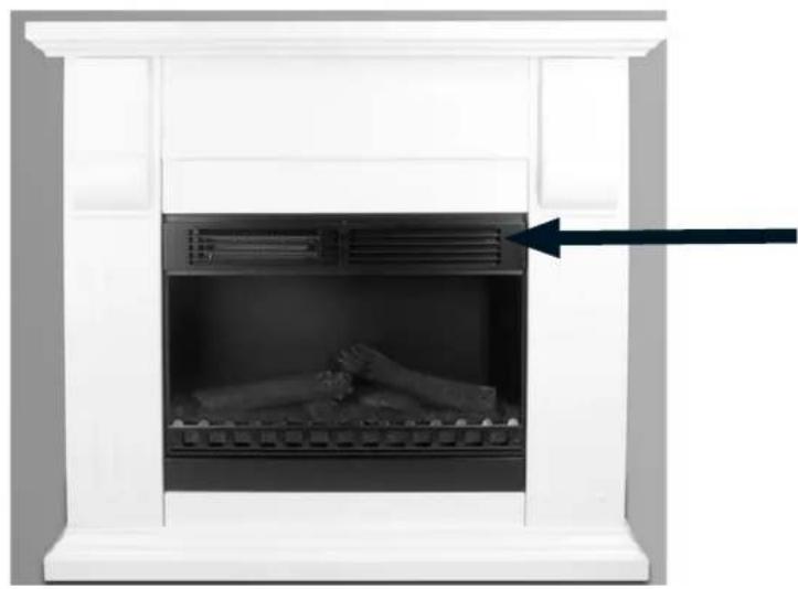
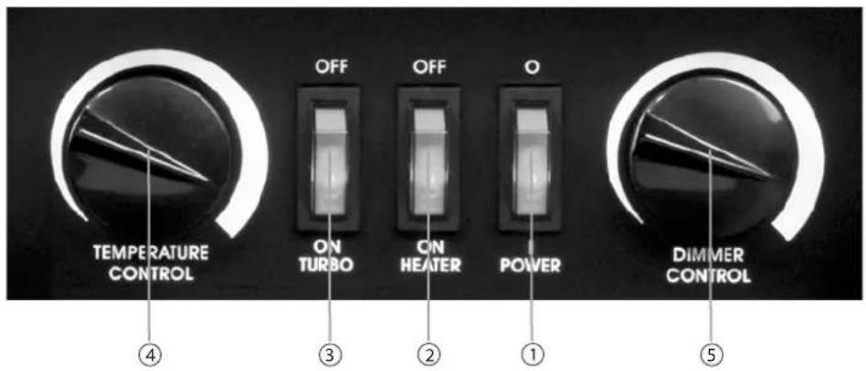
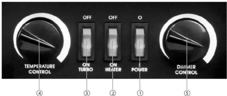
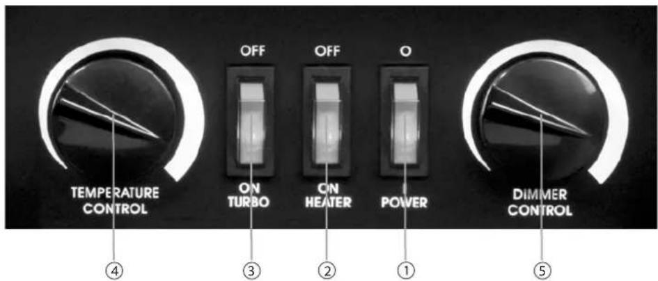
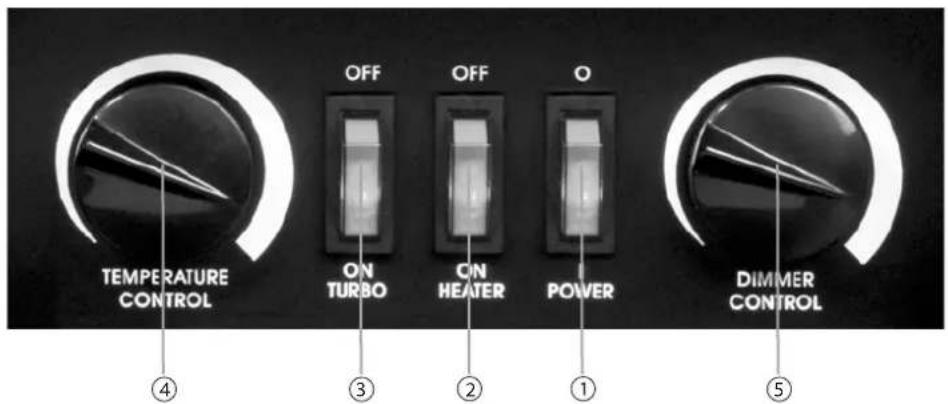
The operating elements are on the front of the appliance, above right and behind the ventilation grille. To operate them, fold the ventilation grille forward.
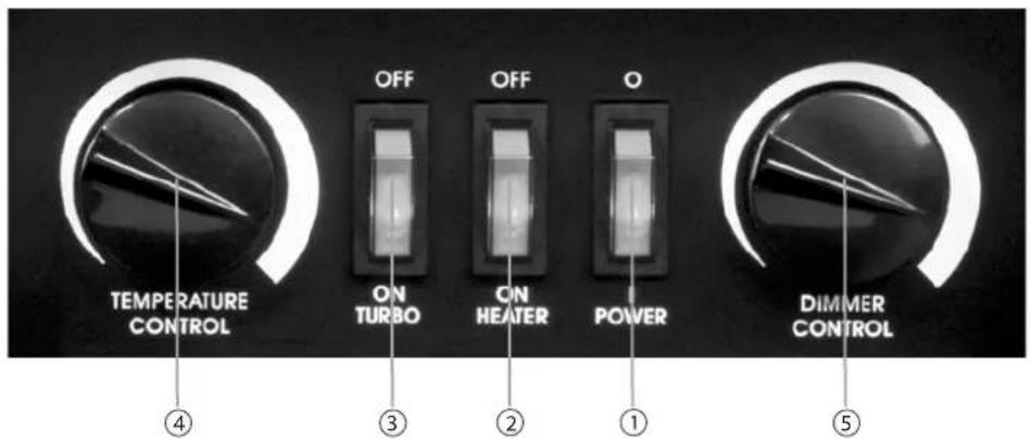
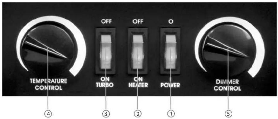
① ON/OFF switch (Flames)
② ON/OFF switch (Heating, level 1)
③ ON/OFF switch (Heating, level 2)
④ Temperature control (Thermostat)
⑤ Dimmer (for flame lamps)
GB
Set up
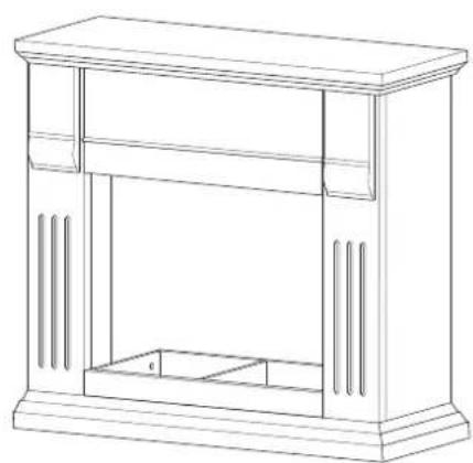
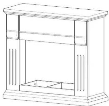
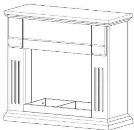
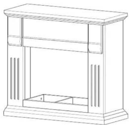
Before the appliance can be set up, the fire surround must be assembled.
NOTICE
Check the contents to make sure everything is there and for visible damage. ▶ Firstly, become familiar with all parts involved in the assembly. ▶
Individual parts of the electric fi replace


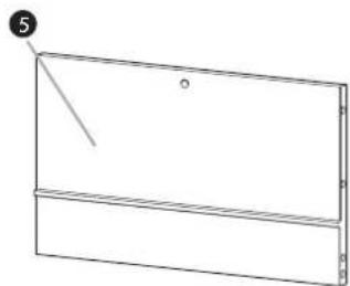
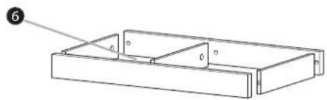
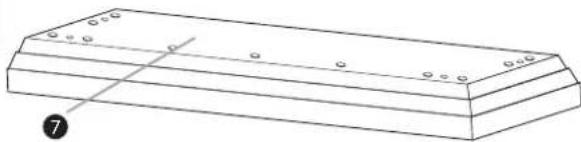
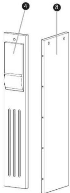
1 left side panel
② left front panel
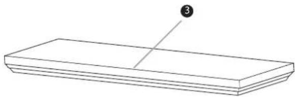
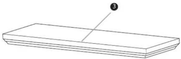
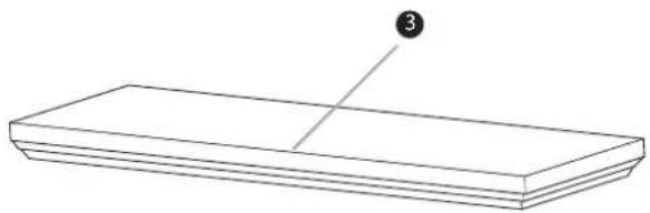
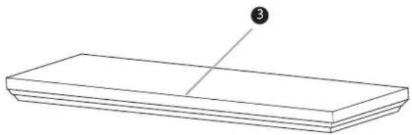
③ top covering panel
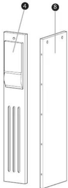
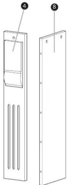
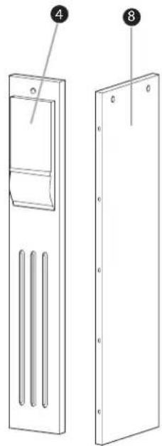
4 right front panel
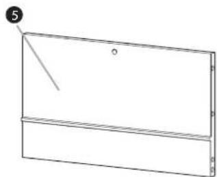
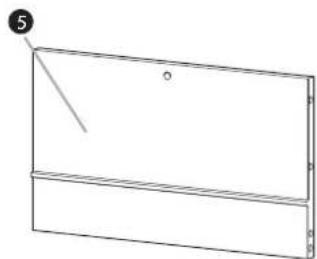
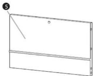
5 centre front panel
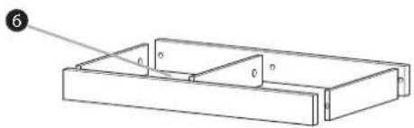
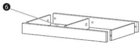
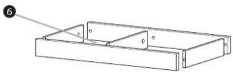
6 Support frame for the fi replace (dismantled)
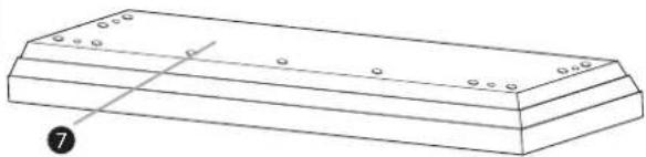
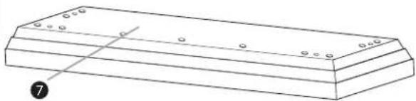
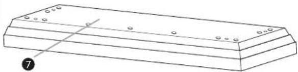
7 Floor plate
⑧ right side panel
Screws and assembly material
GB
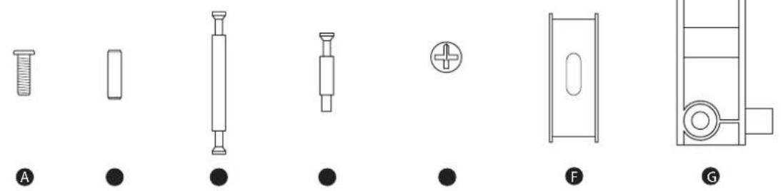
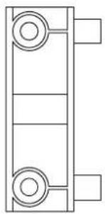
| No.: | Designation: Number: | |
| A | Screws 6 x 25 mm 21 | |
| B | Wood plugs 5 | |
| C | Double locking pin 6 | |
| D | Single locking pin 16 | |
| E | Adapter sleeve 28 | |
| F | Fixing device 2 | |
| G | Connection blocks 4 |
NOTICE
You require a screwdriver for the assembly; this is not supplied.
The assembly of the fi re surround is described in detail in the following.
NOTICE
Carry out the assembly step by step in the order as described.
GB
Assembly
Step 1
Screw 5 single locking pins Ⓓ with a screwdriver into the prepared holes on the left front panel 2.
Insert 5 adapter sleeves E into the 5 large holes of the left side panel 1 Thereby, with the screwdriver line up the adaptor sleeves E so that the arrow on the adaptor sleeves points to the outer edge of the side panel 1.
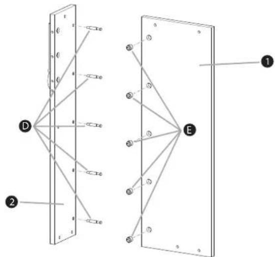
Then, bring the front panel ② and side panel ① together at right angles, so that the locking pins D enter the holes on the left edge of the side panel ①.
When done, screw all 5 adapter sleeves E to the right with the screwdriver until the locking pins are clamped into the adapter sleeves and the panels are seated firmly together and at right angles.
Step 2
Screw 5 single locking pins Ⓓ with a screwdriver into the prepared holes on the right front panel 4.
Insert 5 adapter sleeves E into the 5 large holes of the right side panel 8. Thereby, with the screwdriver line up the adaptor sleeves E so that the arrow on the adaptor sleeves points to the outer edge of the side panel 8.
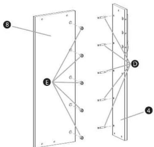
Then, bring the front panel ④ and side panel ⑧ together at right angles, so that the locking pins D enter the holes on the right edge of the side panel.
When done, screw all 5 adapter sleeves E to the right with the screwdriver until the locking pins are clamped into the adapter sleeves and the panels are seated firmly together and at right angles.
Step 3
Take the centre front panel ⑤ and lay it face down.
Then place 6 adapter sleeves E in the 6 large holes. Turn the adapter sleeves with the screwdriver so that the arrows on the adapter sleeves each point to the outer edge of the centre front panel 5.
Insert 6 double locking pins G in the holes on the front sides of the panel and turn the adapter sleeves E with the screwdriver to the right until the locking pins are firmly secured.
◆ Place 2 wood plugs Ⓑ into the holes of the front panel 5.
![graph TD A["Component A"] -->|A| E["Component E"] B["Component B"] -->|B| E C["Component C"] -->|C| E E -->|D| A E -->|E| B E -->|E| C style A fill:#f9f,stroke:#333 style B fill:#f9f,stroke:#333 style C fill:#f9f,stroke:#333 style E fill:#ccf,stroke:#333](/content/2026/06/1340665/images/e323a475e74cef3c5888fd25bae3a8161a1af7cdaca887cc6278cc1396a4a206.jpg)
Step 4
Now connect the so prepared centre front panel 5 with the side panels prepared in steps 1 and 2.
For this, insert 3 adapter sleeves E in the large holes in the side panels. Turn the adapter sleeves E with the screwdriver so that the arrows on the adapter sleeves each point to the outer edge of the side panels.
Then, guide each of the double locking pins © of the centre front panel ⑤ into the corresponding holes in the edges of the side panels.
When done, turn all 6 adapter sleeves E in the centre front panel 5 with the screwdriver to the right, until all parts are at right angles to each other and firmly tightened.
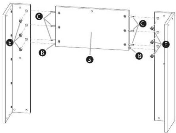

Step 5
Place the floor plate 7 on the floor.
- Insert the 4 connection blocks G in the holes of the floor plate7 and secure them with 4 screws of type A.
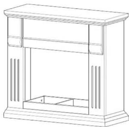
Now take the previously assembled unit and carefully place it on the floor plate as shown in the following diagram.
Then screw together the assembled unit with the connection blocks G on the fl oor plate 7. For this, use 8 screws of the type A (2 screws per connection block).
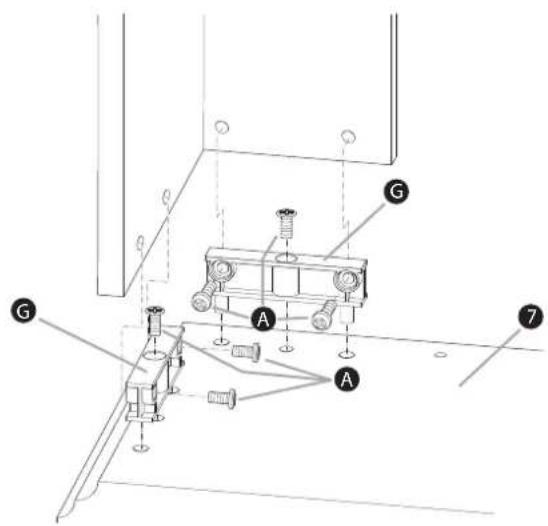
Step 6
Take the top covering panel 3 and place it on the preassembled unit.
Secure the top covering panel ③ from the inner side of the unit with 7 screws of the type A.
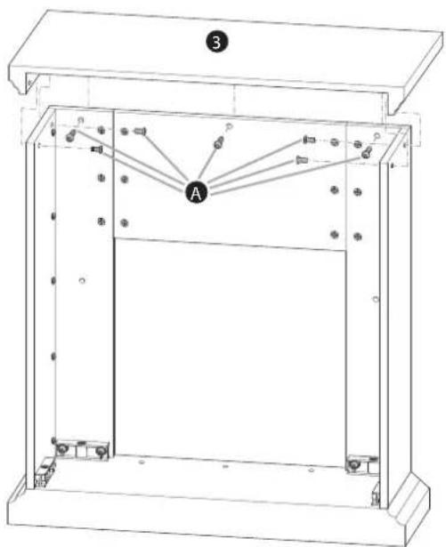
Step 7
Screw the 6 single locking pins Ⓓ with a screwdriver into the holes provided on the front and rear support frame plates.
Place the 6 adapter sleeves E in the large pre-drilled holes in the three middle support frame plates. Thereby, line up the adaptor sleeves E with the screwdriver so that the arrow on the adaptor sleeves points to the outer edge.
Then, bring all of the plates together so that the single locking pins D engage the holes in the middle support frame plates.
When done, screw all adapter sleeves E to the right with the screwdriver until the single locking pins D are clamped into the adapter sleeves E and the panels are seated firmly together and at right angles.
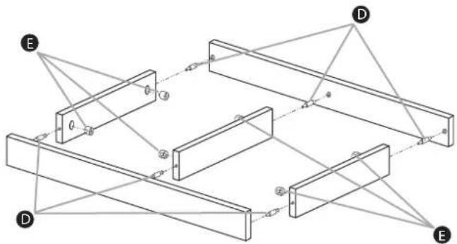
Step 8
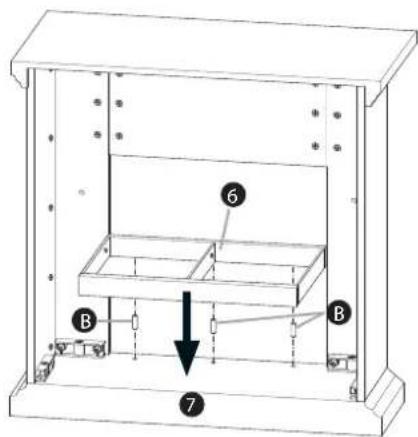
Take the support frame ⑥ and insert 3 wood plugs ⑧ into the holes of the front plate underside.
Then place the support frame ⑥ on the floor plate ⑦ so that the 3 wood plugs fit into the 3 holes in the floor plate.
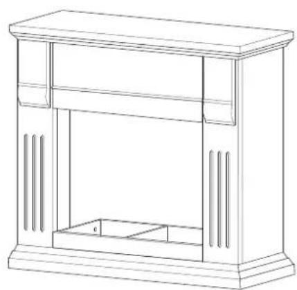
Rear view Front View
Installing the appliance in the fire surround
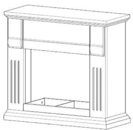
To fi nalise, install the appliance in the assembled fi re surround.
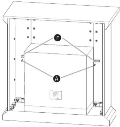
Place the appliance carefully on the base plate (from the rear of the fi re surround) and then push it gently forward as far as it will go into the opening of the fi re surround.
Secure the appliance to the fi re surround at the edges with the fi xing devices and the screws 6 × 25 mm.
- Insert the plug into the mains power socket.
WARNING
Improper laying of the power cable can cause damage to people and property!
Pay heed to the following safety information to avoid these risks:
▶ Do not bend or clamp the power cable and do not lay it tautly.
Do not run the power cable over sharp edges.
Handling and operation
NOTICE
See also "Operating Elements" on page 7.
In this chapter you receive important information for the handling and operation of the appliance.
◆Activate the UP No Of The White replication lights up. Programme in the desired brightness with the Dimmer ⑤.
Then, turn the heater on with the switch ②; the built-in fan starts to run and the heater is working at level 1 (1000 W).
◆ Activate the additional switch ③; the heating is now working at level 2 (2000 W).
Using the thermostat ④, you can set it to the desired temperature. The heat settings switch themselves off after reaching the set temperature range, and switch back on when it becomes cooler.
Switching the appliance on and off
◆ Activate the ON/OFF switch ① to turn the appliance on.
◆ Activeteqlaen@Ny/Offhesorphichnce off.
Maintenance
The maintenance of the appliance is limited to occasional external cleaning.
NOTICE
- Keep the appliance, and in particular the ventilation grille, free from dust and dirt.
Changing the light bulbs

DANGER
Risk of electrocution!
Contact with electricity can be fatal!
Pay heed to the following safety information to avoid the risks of injury:
▶ Switch the appliance off.
Before changing the bulb, unplug the appliance from the mains power source.

ARNING
Risk of injury from sharp edges!
When reaching in through the housing opening, there is a risk of injury from the sharp edges on sheet metal housing and the refl ector mirrors.
Pay heed to the following safety information to avoid these risks:
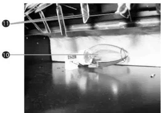
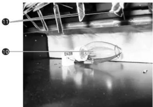
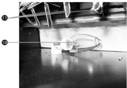
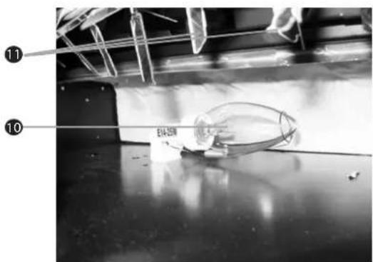
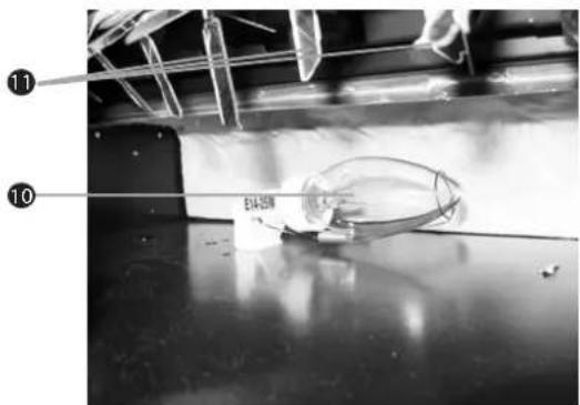
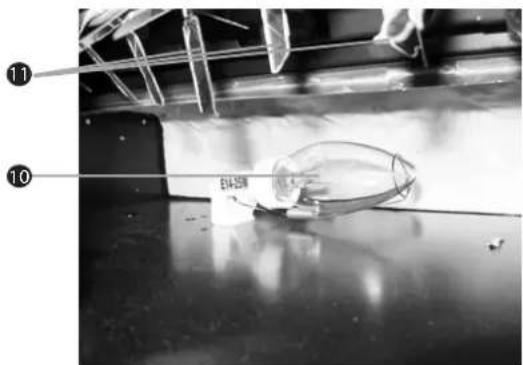
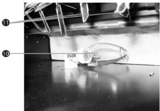
- Do not touch the edges of the housing and the reflector mirror 11 .
▶ Wear protective gloves if necessary.
GB
Switch the appliance off.
Pull the plug from the mains power socket.
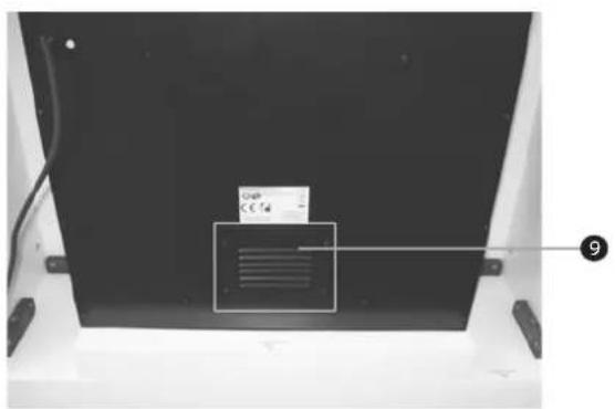
Loosen the four screws on the rear panel and remove the metal ventilation panel ⑨.
- Carefully replace the defective bulb 10 in the light shaft.
♦ Screw the metal ventilation panel ⑨ back onto the appliance rear.
Cleaning
WARNING
Observe the following safety information to avoid risks and property damage: Clean the appliance ONLY when it is switched off and cold.
IMPORTANT
Possible damage to the appliance.
Penetrating moisture can cause damage to the appliance.
In order to avoid irreparable damage, when you are cleaning the appliance ensure that moisture cannot get inside it.
Clean the housing exclusively with a soft damp cloth and a mild dishwashing liquid.
Troubleshooting
In this chapter you will receive important information for the localisation of malfunctions and remedies for them. Observe these instructions in order to avoid risks and damage.
WARNING
Observe the following safety information to avoid risks and property damage:
▶ Repairs to electrical appliances may only be carried out by specialists who have been trained by the manufacturer. Considerable risk for the user and damage to the appliance can occur as a result of incorrect repairs.
Malfunction causes and remedies
The following table will help with localising and remedying minor malfunctions:
| Defect Possible cause Solution | ||
| The appliance is not switched on. Switch the appliance on. | ||
| The flame replication does not light up. | The plug is not inserted. | Insert the plug into the mains power socket. |
| The mains power socket does not supply voltage | Check the fuses | |
| The bulbs are defect. Replace the defective bulbs. | ||
| The appliance does not heat. | Switch 1 is not turned on.Switch 2 is not turned on.Switch 3 is not turned on.Heating level control defective | Switch 1 on.Switch 2 on.Switch 3 on.Inform Customer Services. |
| The fan does not run. | Switch 1 is not turned on.Switch 2 is not turned on.Fan defect. | Switch 1 on.Switch 2 on.Inform Customer Services. |
| The heating is not switched off. | Thermostat 4 falsely adjusted. | Set the thermostat 4 at the required temperature. |
| Temperature control 4 defect. | Inform Customer Services. | |
NOTICE
▶ If you cannot solve the problem with the aforementioned methods, please contact Customer Services.
Storage/Disposal
Storage
Disconnect the plug if you are not intending to use the appliance for a long period.
Store the appliance at a dry locality.
Disposal of the appliance
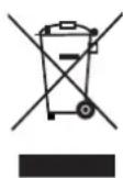
Do not dispose of the apliance in your normal domestic waste. This product is subject to the provisions of European Directive 2002/96/EC-WEEE (Waste Electrical and Electronic Equipment).
Dispose of the appliance through an approved disposal centre or at your community waste facility.
Observe the currently applicable regulations. In case of doubt, please contact your waste disposal centre.

Appendix
Technical data
| General | ||
| Input voltage 220 - 240 V | ~ | |
| Mains frequency 50 Hz | ||
| Power consumption | ||
| Heating level 1 | 1000 | W |
| Heating level 2 | 2000 | W |
| Bulb | ||
| 2 x Bulbs E14 | 2 x 25 W | |
| Ambient temperature +5 to +45 °C | ||
| Humidity (no condensation) 5 to 90 % | ||
| Measurements (W x H x D): 100 x 100 x 39 cm | ||
| Weight approx. 45 kg | ||
Notes on the EC Declaration of Conformity
This appliance complies with, in regard to conformance to the basic requirements and other relevant regulations, the European Directive Low Voltage Directive 2006/95/EC as well as the European Directive for Electromagnetic Compatibility 2004/108/EC.
The complete original declaration of conformity can be obtained from the importer

Warranty
You receive a 3-year warranty for this appliance as of the purchase date. The appliance has been manufactured with care and meticulously examined before delivery.
Please retain your receipt as proof of purchase. In the case of a warranty claim, please make contact by telephone with our Service Department. Only in this way can a post-free despatch for your goods be assured.
NOTICE
The warranty is valid only for material or manufacturing defects not, however, for transport damage, wear and tear or for damage to breakable parts, i.e. switches or rechargeable batteries.
This product is for private use only and is not intended for commercial applications. The warranty becomes void in the event of abusive and improper handling, use of force and internal tampering not carried out by our authorised service branch.
Your statutory rights are not restricted in any way by this warranty. The warranty period will not be extended as a result of repairs made under warranty. This applies also to replacement and repaired parts.
Damages and defects potentially present at the time of purchase must be reported immediately after unpacking or, at the very least, two days after the date of purchase.
Repairs carried out after expiry of the warranty period are subject to payment.
Service
GB Service Great Britain
Tel.: 0871 5000 720 (£ 0.10/Min.)
E-Mail: kompernass@lidl.gb
IAN 66252
IE Service Ireland
Tel.: 1890 930 034
(0,08 EUR/Min., (peak))
(0,06 EUR/Min., (off peak))
E-Mail: kompernass@lidl.ie
IAN 66252
Importer
KOMPERNASS GMBH
BURGSTRASSE 21
44867 BOCHUM, GERMANY
www.kompernass.com
Spis treści
Wprowadzenie 22
G
Krok 6
Krok 8
STRZEŻENIE
Czyszczenie
OSTRZEŻENIE
HU
5. lépés:
6. lépés:
7. lépés:
8. lépés:
EIGYELMEZTETÉS
Tisztítás
EIGYELMEZTETÉS
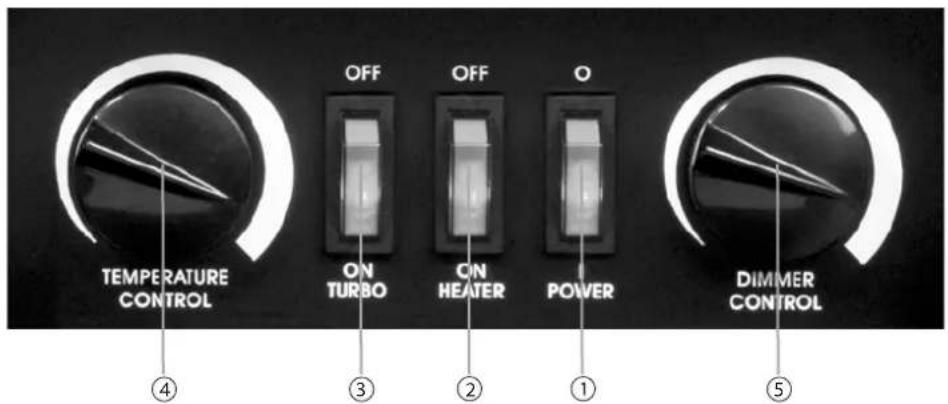
① stikalo za VKLOP/IZKLOP (videz plamenov)
② stikalo za VKLOP/IZKLOP (ogrevanje, 1. stopnja)
③ stikalo za VKLOP/IZKLOP (ogrevanje, 2. stopnja)
④ regulator temperature (termostat)
⑤ stikalo za zatemnitev (za žarnice za videz plamenov)
Sestava
Korak 6
Korak 8
Vgradnja naprave v oblogo
Na koncu napravo vstavite v sestavljeno oblogo kamina.
APOZORILO
Čiščenje
APOZORILO

G
Krok 5
Krok 6
Krok 8
VYSTRAHA
Čištění
ΔVÝSTRAHA
SK

G
Krok 5
Položte podstavec 7 pred seba na podlahu.
Krok 6
Vezmite hornú kryciu dosku 3 a nasad'te ju na zmontovanú jednotku.
SK
VAROVANIE
SK
Čistenie
⚠VAROVANIE
DE AT CH

G
Schritt 6
Schritt 7
Schritt 8
WARNING
Reinigung
WARNING

- SAFETY 4
- SETTING UP AND CONNECTING ..... 5
- OPERATING COMPONENTS ..... 7
- SET UP 8
- ASSEMBLY 10
- HANDLING AND OPERATION ..... 15
- MAINTENANCE 15
- CLEANING 16
- TROUBLESHOOTING 16
- STORAGE/DISPOSAL 17
- APPENDIX 18
- INTRODUCTION
- INFORMATION FOR THESE OPERATING INSTRUCTIONS
- COPYRIGHT
- LIMITED LIABILITY
- WARNINGS
- DANGER
- A WARNING AT THIS DANGER LEVEL INDICATES A THREATENINGLY DANGEROUS SITUATION
- WARNING
- A WARNING AT THIS DANGER LEVEL INDICATES A POTENTIALLY DANGEROUS SITUATION
- IMPORTANT
- A WARNING OF THIS DANGER LEVEL SIGNIFIES POSSIBLE PROPERTY DAMAGE
- NOTICE
- INTENDED USE
- RISKS FROM UNINTENDED USE
- SAFETY
- DO NOT COVER THE APPLIANCE
- RISK OF ELECTROCUTION
- A POTENTIALLY FATAL SITUATION CAN ARISE FROM CONTACT WITH LIVE WIRES OR COMPONENTS
- BASIC SAFETY INSTRUCTIONS
- SETTING UP AND CONNECTING
- SAFETY NOTICES
- DURING COMMISSIONING OF THE APPLIANCE, DAMAGE MAY OCCUR TO PERSONS AND PROPERTY
- ITEMS SUPPLIED AND DELIVERY CHECKS
- DISPOSAL OF THE PACKAGING
- INSTALLATION REQUIREMENTS
- FIRE HAZARD DUE TO MATERIAL CONTACT
- IF THE HEATER MAKES CONTACT WITH FLAMMABLE MATERIALS, THERE IS A RISK OF FIRE
- BEFORE THE FIRST USE
- ELECTRICAL CONNECTION
- OPERATING COMPONENTS
- SET UP
- INDIVIDUAL PARTS OF THE ELECTRIC FI REPLACE
- SCREWS AND ASSEMBLY MATERIAL
- ASSEMBLY
- STEP 1
- STEP 2
- STEP 3
- STEP 4
- STEP 5
- STEP 6
- STEP 7
- STEP 8
- INSTALLING THE APPLIANCE IN THE FIRE SURROUND
- IMPROPER LAYING OF THE POWER CABLE CAN CAUSE DAMAGE TO PEOPLE AND PROPERTY
- HANDLING AND OPERATION
- SWITCHING THE APPLIANCE ON AND OFF
- MAINTENANCE
- CHANGING THE LIGHT BULBS
- CONTACT WITH ELECTRICITY CAN BE FATAL
- ARNING
- RISK OF INJURY FROM SHARP EDGES
- WHEN REACHING IN THROUGH THE HOUSING OPENING, THERE IS A RISK OF INJURY FROM THE SHARP EDGES ON SHEET METAL HOUSING AND THE REFL ECTOR MIRRORS
- CLEANING
- POSSIBLE DAMAGE TO THE APPLIANCE
- TROUBLESHOOTING
- MALFUNCTION CAUSES AND REMEDIES
- STORAGE/DISPOSAL
- STORAGE
- DISPOSAL OF THE APPLIANCE
- APPENDIX
- TECHNICAL DATA
- NOTES ON THE EC DECLARATION OF CONFORMITY
- WARRANTY
- SERVICE
- IMPORTER
- SPIS TREŚCI
- WPROWADZENIE 22
- KROK 6
- KROK 8
- STRZEŻENIE
- CZYSZCZENIE
- OSTRZEŻENIE
- LÉPÉS
- EIGYELMEZTETÉS
- TISZTÍTÁS
- SESTAVA
- KORAK 6
- KORAK 8
- VGRADNJA NAPRAVE V OBLOGO
- APOZORILO
- 74
- ČIŠČENJE
- KROK 5
- VYSTRAHA
- ČIŠTĚNÍ
- ΔVÝSTRAHA
- VAROVANIE
- ČISTENIE
- ⚠VAROVANIE
- SCHRITT 6
- SCHRITT 7
- SCHRITT 8
- REINIGUNG
Brand : SILVERCREST
Model : SEKU 2000 A1
Category : Fireplace