
M-100FX - Audio Mixer ROLAND - Free user manual and instructions
Find the device manual for free M-100FX ROLAND in PDF.

User questions about M-100FX ROLAND
0 question about this device. Answer the ones you know or ask your own.
Ask a new question about this device
Download the instructions for your Audio Mixer in PDF format for free! Find your manual M-100FX - ROLAND and take your electronic device back in hand. On this page are published all the documents necessary for the use of your device. M-100FX by ROLAND.
USER MANUAL M-100FX ROLAND
Thank you, and congratulations on your choice of the Edirol M-100FX.
Before using this unit, carefully read the sections entitled: “USING THE UNIT SAFELY” and “IMPORTANT NOTES” (p. 2; p. 4). These sections provide important information concerning the proper operation of the unit. Additionally, in order to feel assured that you have gained a good grasp of every feature provided by your new unit, Owner’s manual should be read in its entirety. The manual should be saved and kept on hand as a convenient reference.
USING THE UNIT SAFELY
INSTRUCTIONS FOR THE PREVENTION OF FIRE, ELECTRIC SHOCK, OR INJURY TO PERSONS
About ⚠️ WARNING and ⚠️ CAUTION Notices
| ⚠ WARNING | Used for instructions intended to alert the user to the risk of death or severe injury should the unit be used improperly. |
| ⚠ CAUTION | Used for instructions intended to alert the user to the risk of injury or material damage should the unit be used improperly.* Material damage refers to damage or other adverse effects caused with respect to the home and all its furnishings, as well to domestic animals or pets. |
About the Symbols
| The △ symbol alerts the user to important instructions or warnings. The specific meaning of the symbol is determined by the design contained within the triangle. In the case of the symbol at left, it is used for general cautions, warnings, or alerts to danger. | |
| The ⊙ symbol alerts the user to items that must never be carried out (are forbidden). The specific thing that must not be done is indicated by the design contained within the circle. In the case of the symbol at left, it means that the unit must never be disassembled. | |
| The ● symbol alerts the user to things that must be carried out. The specific thing that must be done is indicated by the design contained within the circle. In the case of the symbol at left, it means that the power-cord plug must be unplugged from the outlet. |
ALWAYS OBSERVE THE FOLLOWING
WARNING
- Before using this unit, make sure to read the instructions below, and the Owner's Manual.
- Do not open (or modify in any way) the unit or its AC adaptor.
- Do not attempt to repair the unit, or replace parts within it (except when this manual provides specific instructions directing you to do so). Refer all servicing to your retailer, the nearest Roland Service Center, or an authorized Roland distributor, as listed on the “Information” page.
-
Never use or store the unit in places that are:
-
Subject to temperature extremes (e.g., direct sunlight in an enclosed vehicle, near a heating duct, on top of heat-generating equipment); or are
- Damp (e.g., baths, washrooms, on wet floors); or are
- Humid; or are
- Exposed to rain; or are
- Dusty; or are
- Subject to high levels of vibration.
- Make sure you always have the unit placed so it is level and sure to remain stable. Never place it on stands that could wobble, or on inclined surfaces.


WARNING

- Be sure to use only the AC adaptor supplied with the unit. Also, make sure the line voltage at the installation matches the input voltage specified on the AC adaptor's body. Other AC adaptors may use a different polarity, or be designed for a different voltage, so their use could result in damage, malfunction, or electric shock.
- Do not excessively twist or bend the power cord, nor place heavy objects on it. Doing so can damage the cord, producing severed elements and short circuits. Damaged cords are fire and shock hazards!
- This unit, either alone or in combination with an amplifier and headphones or speakers, may be capable of producing sound levels that could cause permanent hearing loss. Do not operate for a long period of time at a high volume level, or at a level that is uncomfortable. If you experience any hearing loss or ringing in the ears, you should immediately stop using the unit, and consult an audiologist.
- Do not allow any objects (e.g., flammable material, coins, pins); or liquids of any kind (water, soft drinks, etc.) to penetrate the unit.


WARNING
- Immediately turn the power off, remove the AC adaptor from the outlet, and request servicing by your retailer, the nearest Roland Service Center, or an authorized Roland distributor, as listed on the "Information" page when:
- The AC adaptor or the power-supply cord has been damaged; or
- If smoke or unusual odor occurs
- Objects have fallen into, or liquid has been spilled onto the unit; or
- The unit has been exposed to rain (or otherwise has become wet); or
-
The unit does not appear to operate normally or exhibits a marked change in performance.
-
In households with small children, an adult should provide supervision until the child is capable of following all the rules essential for the safe operation of the unit.
- Protect the unit from strong impact. (Do not drop it!)
- Do not force the unit's power-supply cord to share an outlet with an unreasonable number of other devices. Be especially careful when using extension cords—the total power used by all devices you have connected to the extension cord's outlet must never exceed the power rating (watts/amperes) for the extension cord. Excessive loads can cause the insulation on the cord to heat up and eventually melt through.
- Before using the unit in a foreign country, consult with your retailer, the nearest Roland Service Center, or an authorized Roland distributor, as listed on the “Information” page.
- DO NOT play a CD-ROM disc on a conventional audio CD player. The resulting sound may be of a level that could cause permanent hearing loss. Damage to speakers or other system components may result.


CAUTION
- The unit and the AC adaptor should be located so their location or position does not interfere with their proper ventilation.
- Always grasp only the output plug or the body of the AC adaptor when plugging into, or unplugging from, this unit or an outlet.
- Any accumulation of dust between the AC adaptor and the power outlet can result in poor insulation and lead to fire. Periodically wipe away such dust with a dry cloth. Also, disconnect the power plug from the power outlet whenever the unit is to remain unused for an extended period of time.
- Try to prevent cords and cables from becoming entangled. Also, all cords and cables should be placed so they are out of the reach of children.
- Never climb on top of, nor place heavy objects on the unit.
- Never handle the AC adaptor body, or its output plugs, with wet hands when plugging into, or unplugging from, an outlet or this unit.
- Before moving the unit, disconnect the AC adaptor and all cords coming from external devices.
- Before cleaning the unit, turn off the power and unplug the AC adaptor from the outlet.
- Whenever you suspect the possibility of lightning in your area, disconnect the AC adaptor from the outlet.
- Should you remove the ground terminal screw, make sure to put them in a safe place out of children's reach, so there is no chance of them being swallowed accidentally.
- Always turn the phantom power off when connecting any device other than condenser microphones that require phantom power. You risk causing damage if you mistakenly supply phantom power to dynamic microphones, audio playback devices, or other devices that don't require such power. Be sure to check the specifications of any microphone you intend to use by referring to the manual that came with it.
(This instrument's phantom power: 48 V DC, 10 mA Max)


In addition to the items listed under “USING THE UNIT SAFELY” on pages 2 and 3, please read and observe the following:
Power Supply
- Do not use this unit on the same power circuit with any device that will generate line noise (such as an electric motor or variable lighting system).
- The AC adaptor will begin to generate heat after long hours of consecutive use. This is normal, and is not a cause for concern.
- Before connecting this unit to other devices, turn off the power to all units. This will help prevent malfunctions and/or damage to speakers or other devices.
Placement
- Using the unit near power amplifiers (or other equipment containing large power transformers) may induce hum. To alleviate the problem, change the orientation of this unit; or move it farther away from the source of interference.
- This device may interfere with radio and television reception. Do not use this device in the vicinity of such receivers.
- Noise may be produced if wireless communications devices, such as cell phones, are operated in the vicinity of this unit. Such noise could occur when receiving or initiating a call, or while conversing. Should you experience such problems, you should relocate such wireless devices so they are at a greater distance from this unit, or switch them off.
- When moved from one location to another where the temperature and/or humidity is very different, water droplets (condensation) may form inside the unit. Damage or malfunction may result if you attempt to use the unit in this condition. Therefore, before using the unit, you must allow it to stand for several hours, until the condensation has completely evaporated.
Maintenance
- For everyday cleaning wipe the unit with a soft, dry cloth or one that has been slightly dampened with water. To remove stubborn dirt, use a cloth impregnated with a mild, non-abrasive detergent. Afterwards, be sure to wipe the unit thoroughly with a soft, dry cloth.
- Never use benzine, thinners, alcohol or solvents of any kind, to avoid the possibility of discoloration and/or deformation.
Additional Precautions
- Use a reasonable amount of care when using the unit's buttons, sliders, or other controls; and when using its jacks and connectors. Rough handling can lead to malfunctions.
- When connecting / disconnecting all cables, grasp the connector itself—never pull on the cable. This way you will avoid causing shorts, or damage to the cable's internal elements.
- To avoid disturbing your neighbors, try to keep the unit's volume at reasonable levels. You may prefer to use headphones, so you do not need to be concerned about those around you (especially when it is late at night).
- When you need to transport the unit, package it in the box (including padding) that it came in, if possible. Otherwise, you will need to use equivalent packaging materials.
- Use a cable from Roland to make the connection. If using some other make of connection cable, please note the following precautions.
- Some connection cables contain resistors. Do not use cables that incorporate resistors for connecting to this unit. The use of such cables can cause the sound level to be extremely low, or impossible to hear. For information on cable specifications, contact the manufacturer of the cable.
Handling CD-ROMs
- Avoid touching or scratching the shiny underside (encoded surface) of the disc. Damaged or dirty CD-ROM discs may not be read properly. Keep your discs clean using a commercially available CD cleaner.
Copyright
- When exchanging audio signals through a digital connection with an external instrument, this unit can perform recording without being subject to the restrictions of the Serial Copy Management System (SCMS). This is because the unit is intended solely for musical production, and is designed not to be subject to restrictions as long as it is used to record works (such as your own compositions) that do not infringe on the copyrights of others. (SCMS is a feature that prohibits second-generation and later copying through a digital connection. It is built into MD recorders and other consumer digital-audio equipment as a copyright-protection feature.) - Do not use this unit for purposes that could infringe on a copyright held by a third party. We assume no responsibility whatsoever with regard to any infringements of third-party copyrights arising through your use of this unit.
USING THE UNIT SAFELY....2
IMPORTANT NOTES ......4
Features of the M-100FX 9
Check the contents of the package....10
Basic operation ...... 11
Names of things and what they do....12
Panel....12
Rear panel....17
Block diagram 18
Basic operation....19
Connecting monitor speakers or headphones....19
Adjusting the volume....19
Connecting a mic 20
Connecting a mic to input audio 20
Adjusting the gain and level (volume) 22
Connecting audio devices 23
Connecting a stereo set or MD 23
Connecting the recording device....23
Adjusting the input level (volume) 23
Connecting the M-100FX to your computer 25
Adjusting the input level (volume) 26
Using the external input/output jacks (AUX) 28
Using the digital output jacks....30
Connecting monitor speakers that have digital input jacks 30
Connecting an MD recorder 30
Audio/Voice effects....31
How to apply effects....31
Effect types 32
Effect parameters....33
Deutsch
How to apply reverb....102
How digital reverb works....103
Reverb types....103
Reverb time 104
Applications ...... 105
Mixing....106
Applying effects....108
Applying reverb....110
Removing noise ....111
Effect applications....113
Supplementary information...... 123
Connecting the M-100FX to your computer ....124
Windows XP/2000 users....125
Windows Me users....126
Windows 98 users....128
Settings and checking 131
Macintosh users....135
Deutsch
Connecting the M-100FX to your computer ....139
Windows XP/2000-Anwender 139
Connecting the M-100FX to your computer ....145
Windows XP/2000 145
Connecting the M-100FX to your computer ....151
Connecting the M-100FX to your computer ....157
Installing the special driver (Windows)....163
Driver settings....166
Installing the special driver (Macintosh) 168
Settings for your software 169
Troubleshooting....170
Problems with the M-100FX.... 170
Problems related to the special driver....173
Deleting the special driver 175
Specifications....176
Index....179
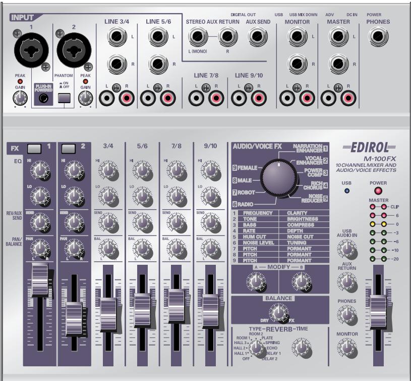
Features of the M-100FX
The M-100FX is a high-quality, 10-channel mixer with audio-processing effects built in, making it an ideal choice for use with video editing.
Supports microphones, cassette tape recorders, CD players, and MD players
The M-100FX provides ten analog channels, with phantom-powered XLR jacks for mic inputs 1 and 2. A connector for a plug-in-powered mic is also provided. For output, it provides phone jacks, RCA phono jacks, and digital output jacks (coaxial/optical).
Audio processing for a variety of vocal sources
The built-in audio/voice effects processing provides nine types of effects for processing vocal sources, as well as reverb and delay, making the M-100FX an ideal choice for video editing applications.
Easy connection to your personal computer
The M-100FX can be connected to your computer via its USB connector, and used as a high-quality audio device to obtain audio material for use with your nonlinear video editing software.
Check the contents of the package
The M-100FX package contains the following items. As soon as you open the package, please check that the following items are present. If anything is missing, please contact the dealer where you purchased the M-100FX.
■ The M-100FX (main unit)
■ AC adaptor
This is a dedicated AC adaptor. Do not use any other AC adaptor with the M-100FX, since doing so can cause malfunction.
■ Computer connection cable (USB cable)
Use this cable when connecting the M-100FX's USB connector to the USB connector of your computer.
■ Owner's manual
This is the manual you are reading. It explains the functionality and connections of the M-100FX, and gives actual examples of how you can use it.
■ CD-ROM (special drivers)
This CD contains the special drivers you will need when connecting the M-100FX to your computer in Advanced mode. If you are not using Advanced mode, you will not need these drivers. ( Using Advance mode (p. 163))
Basic operation
Names of things and what they do
Panel
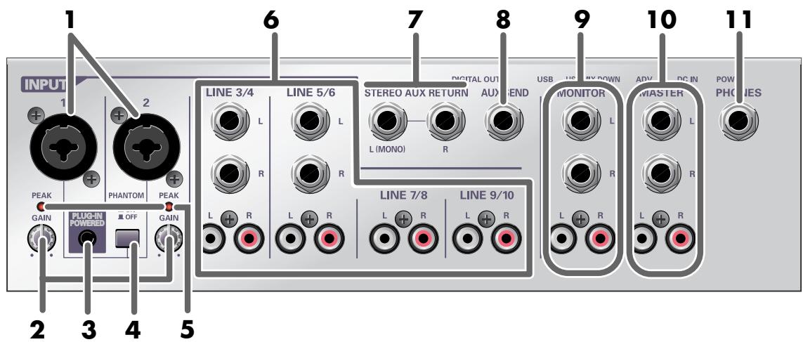
1 .....Mic input jacks 1, 2 (INPUT 1, 2)
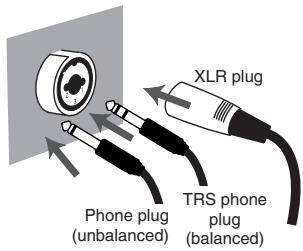
These are input jacks for analog audio. Each jack can be used either as an XLR type or phone type jack. You can use either a balanced or unbalanced connection for either type.
The XLR type jacks provide 48 V phantom power, allowing you to use condenser mics that require phantom power. If you are using such a mic, turn the phantom power switch on.
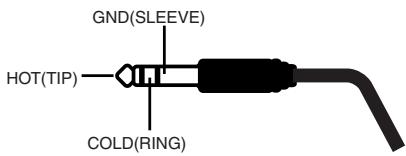
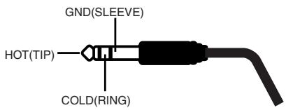
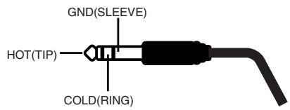
* This instrument is equipped with balanced (XLR/TRS) type input jacks. Wiring diagrams for these jacks are shown at right. Make connections after first checking the wiring diagrams of other equipment you intend to connect.
* Always turn the phantom power off when connecting any device other than condenser microphones that require phantom power. You risk causing damage if you mistakenly supply phantom power to dynamic microphones, audio playback devices, or other devices that don't require such power. Be sure to check the specifications of any microphone you intend to use by referring to the manual that came with it.
(This instrument's phantom power: 48 V DC, 10 mA Max)
2 .....Input level knobs (GAIN)
These knobs adjust the input level to the mic input jacks.
3 .....Plug-in powered input
This jack allows connection of a miniature condenser mic that requires a power supply. 5 V of power is supplied from the plug-in powered mic input. Only a plug-in power compatible mic may be used with this input. If mics are connected to both the plug-in powered mic input and to mix input jack 1 (XLR type/phone type), the signal from mic input jack 1 (XLR type/phone type) will be ignored.
* If a mic is connected to the plug-in powered mic jack, the input level knob (GAIN) will not adjust the input level.

1:GND
2:HOT
3:COLD
4 .....Phantom power switch (PHANTOM)
This is an on/off switch for the phantom power that is supplied to the XLR type mic input jacks.
* If a device that does not require phantom power is connected to the XLR type jack, you must turn phantom power off; failing to do so will cause malfunctions.
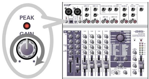
5 .....Peak indicators (PEAK)
These indicators respond to the level of the sound that is being input to the mic input jacks. If the input level is excessive, these indicators will light in red. Adjust the input level knobs (GAIN) so that the peak indicators do not light.
6 .....Line input jacks 3/4–9/10 (LINE INPUT)
Cables with either phone plugs or RCA phono plugs can be connected here.
Line input jacks 3/4–5/6 provide both phone and RCA phono connections. If both are connected simultaneously, the sound from the phone jack will take priority; the sound from the RCA phono jack will be ignored.
Line input jacks 7/8–9/10 provide only RCA phono type connections.
Use the phone jacks to connect cables having phone plugs, such as those from electronic musical instruments or effects processors. Use the RCA phono jacks to connect cables having RCA phono plugs, from audio devices such as your stereo system or CD player.
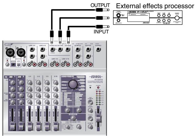
7 .....External input jacks (AUX RETURN)
These are supplementary input jacks for receiving external sources. If you output sound from the external output jack (AUX SEND) and process it with an external effects processor, you can use these external input jacks to receive the sound from the effects processor. You can also use these jacks to connect an external device in the same way as when using the line inputs.
Cables with phone plugs can be connected here. If you are inputting a monaural signal, connect it to the L (MONO) jack.
8 .....External output jack (AUX SEND)
This is a supplementary output jack for sending sound to an external device such as an external effects processor. If you want to use an external effects processor to process sound from the M-100FX, connect this jack to the input jack of your effects processor.
A phone plug cable can be connected here.
This jack outputs the sound adjusted by the REVERB/AUX send level knobs of each channel. The signal sent from this jack is monaural.
9 .....Monitor output jacks (MONITOR)
Connect these jacks to your external monitor system. These jacks output the sound that has been mixed and processed by the M-100FX. The monitor volume knob adjusts the volume of these jacks.
10...Master output jacks (MASTER)
Connect these jacks to your external monitor system or recorder. These jacks output the sound that has been mixed and processed by the M-100FX. The master volume fader adjusts the volume of these jacks.
11 ...Headphone jack (PHONES)
Connect your headphones to this jack. Even if you are using headphones, sound will still be output from the master output jacks. The headphone volume knob adjusts the volume of this jack.
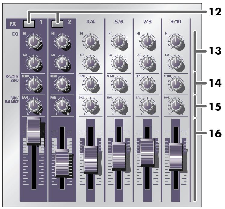
12...Effect switches (FX)
These switches select whether the audio/voice effect will be on (effect applied) or off (effect not applied). The switch will light in red when on. If the effect switches of both CH 1 and 2 are on, the Stereo Control feature will be activated. ( Stereo Control (p. 111))

What is an effect?
An “effect” is a type of processing that modifies or transforms the sound in a special way, sometimes giving it an entirely different character.
13 ... Equalizer knobs (HI/LO)
These knobs adjust the tone. HI adjusts the high-frequency range (10 kHz), and LO adjusts the low-frequency range (200 Hz).
14...Reverb/AUX send level knobs (REV/AUX SEND)
These knobs adjust the level of the signal that is sent to the internal reverb and the external output jack. If you are using the internal reverb, use the reverb/AUX send level knobs to adjust the depth of reverb.
15 ...Pan/balance knobs (PAN/BALANCE)
These knobs adjust the left/right balance of the sound that is sent to the master output jacks.
For CH 1 and 2, these knobs adjust the pan. When converting a monaural input signal into stereo, they adjust the left/right balance (pan).
For CH 3/4–9/10, these knobs adjust the balance. They adjust the left/right balance of the stereo audio input signal.
* If sound is being input only to the L channel of CH 3/4–9/10 and you turn the pan/balance knob all the way to the R (right) position, you will not hear any of the input sound.
16...Input level faders
These faders adjust the volume of each input channel.
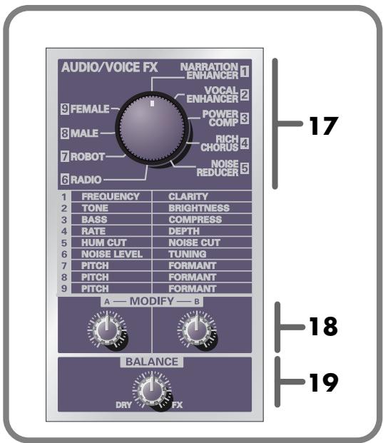
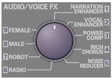
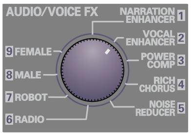
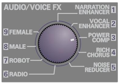
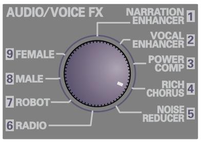
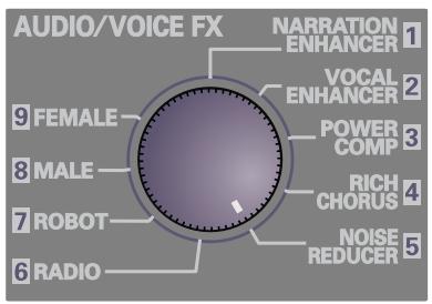
17 ... Audio/voice effect knob (AUDIO/VOICE FX)
This knob selects the type of effect.
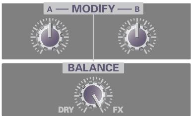
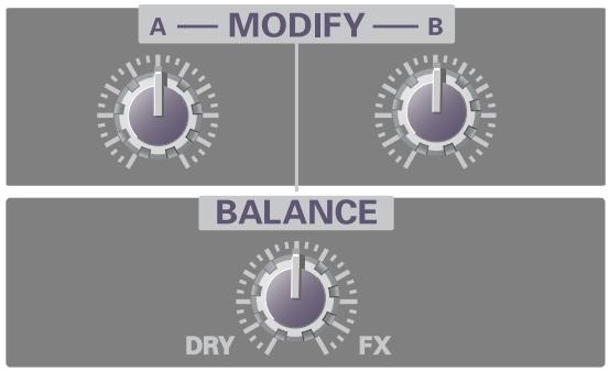
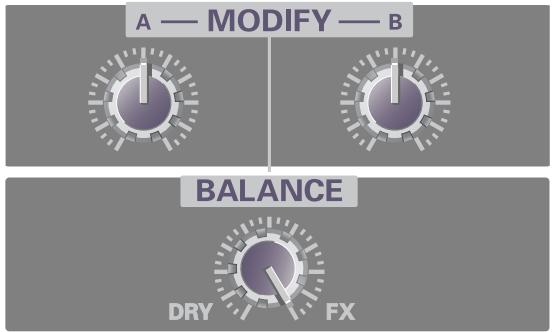
18... Effect adjustment knobs (MODIFY) A, B
These adjust the depth or character of the effect.
For details, refer to Audio/Voice effects (p. 31).
19... Effect balance knob (BALANCE)
This knob adjusts the balance between the original (unprocessed) sound and the effect sound. Turning the knob toward the DRY (left) position will make the sound closer to the original sound, and turning it toward FX (right) will increase the effect sound, producing a stronger effect.

The audio/voice effect can be applied only to the audio that is input from mic input jacks 1 and 2 (CH1, 2).
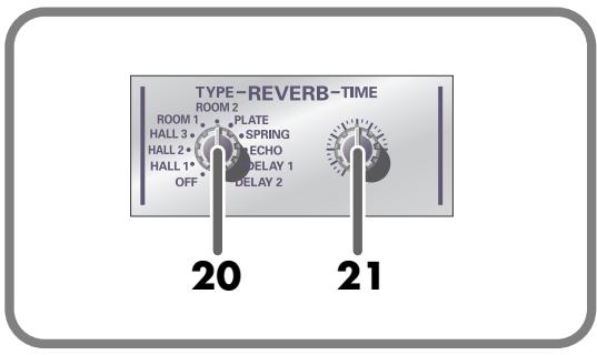
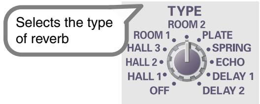
20...Reverb type select knob
This knob selects the type of reverb.
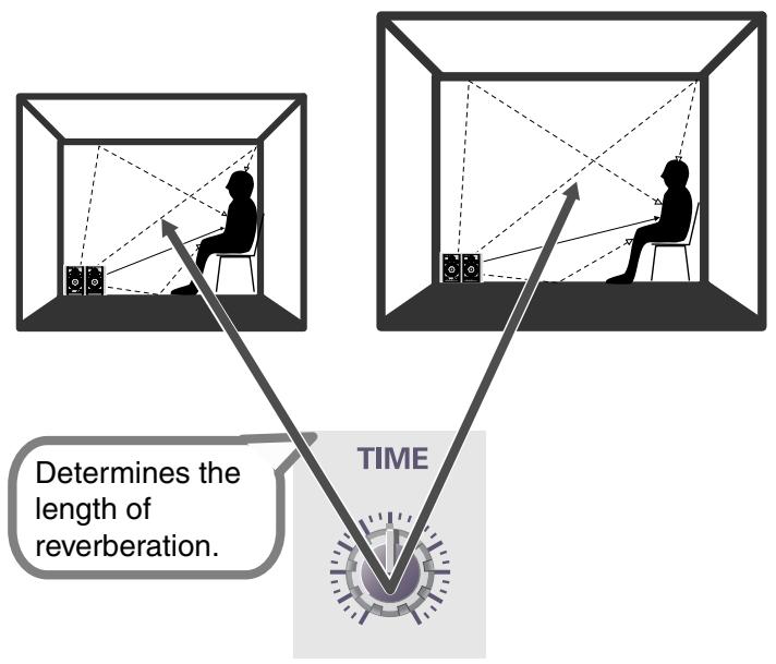
21 ... Reverb time adjustment knob
This knob adjusts the duration (length) of the reverberation.

What is reverb?
Reverb is an effect that creates the reverberation characteristic of sounds heard in an acoustical space such as a concert hall. It adds depth and spaciousness to the sound.
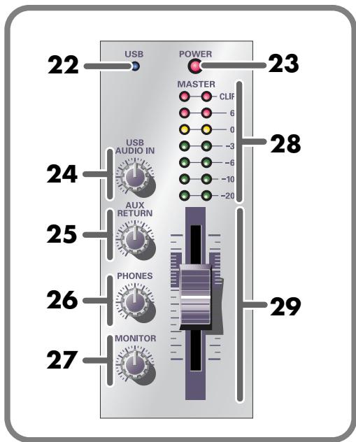
22... USB indicator
When the M-100FX is connected to your computer via a USB cable, this indicator shows the status of the connection.
This indicator lights in green when the connection is usable. If a USB cable is not connected, the indicator will not be lit.
23 ... Power indicator
This indicator lights in red when the power switch is on.
24... USB input level knob
This knob adjusts the input level of the audio signal that is sent from your computer to the M-100FX via the USB cable.
25...AUX input level knob
This knob adjusts the input level of the audio signal that is input to the external input jacks (AUX RETURN).
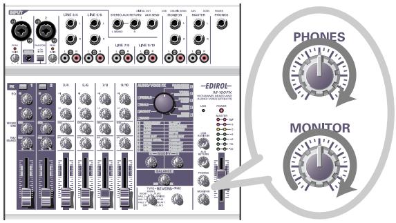
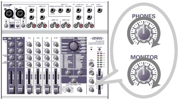
26 ...Headphone volume knob
This knob adjusts the volume of the sound that is output from the headphone jack.
27 ...Monitor volume knob
This knob adjusts the volume of the sound that is output from the monitor output jacks.
28 ...Master volume indicator
This indicator progressively lights from green to red to indicate the volume that is being output from the master output jacks. Use the master volume fader to adjust the volume so that this indicator does not reach the red indication.
29 ... Master volume fader
This fader adjusts the volume that is output from the master output jacks.
Rear panel
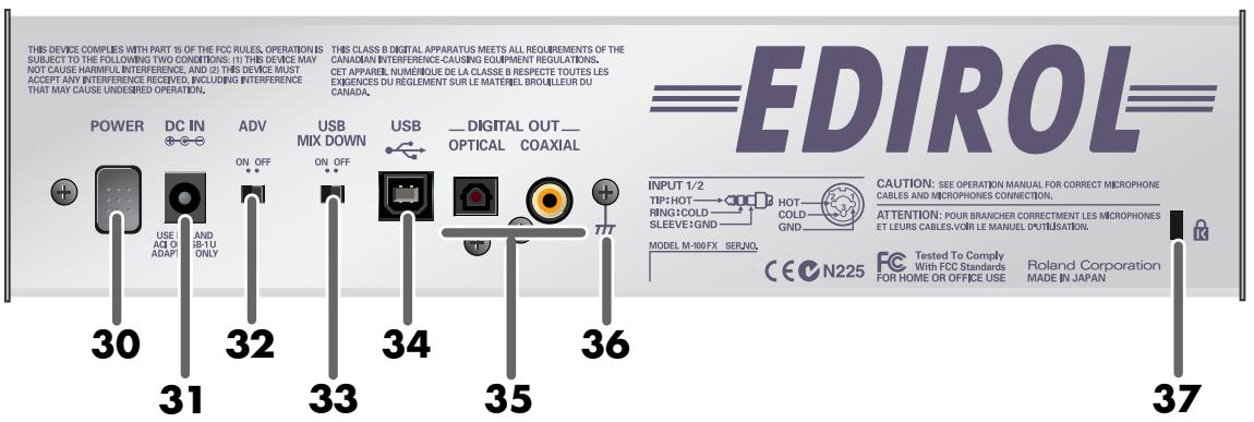
30...Power switch
Press this switch to turn the power on/off. The power is on when this switch is in the inward position.
31 ...AC adaptor jack
This is the power supply jack. Connect the included AC adaptor here.
32...ADVANCE (mode select) switch
This switches the operating mode when the M-100FX is connected to your computer via a USB cable. Normally, you will leave this in the OFF position.
You cannot change the setting of this switch while the M-100FX is operating.
After you change the setting, you must turn the power of the M-100FX off, then on again.
* Some music production and audio editing software uses more sophisticated software (such as WDM or ASIO) to transfer audio data between the computer and peripheral devices. If you are using this type of software, you must put the M-100FX in Advanced mode and install the special driver. If the M-100FX's ADVANCE switch is in the ON position, it will be in Advanced mode. For details on installing the special driver, refer to Using Advance mode (p. 163).
33 ...USB mix down switch
This switch selects whether audio signals sent from your computer via USB to the M-100FX will be returned to the computer. Normally, you will leave this in the OFF position.
* If this is ON, the same sound that is being output from the master output jacks will be sent to the USB connector. If this is OFF, the sound that is being output from the master output jacks minus the sound that is input from the USB connector will be sent to the USB connector.
34...USB connector
Use a USB cable connected here to connect the M-100FX to your computer.
35 ...Digital output jacks
These jacks send the digital audio signal from the M-100FX to an external digital audio device. Use these jacks if you want to digitally connect the M-100FX to a digital audio device such as an MD or DAT recorder. You can also connect these connectors to amplified speakers that have digital input jacks.
| OPTICAL | Use an optical digital cable to make connections |
| COAXIAL | Use a coaxial cable to make connections |
* The digital output jacks output the same signal as the master output jacks.
36 ... Ground terminal
In some cases, depending on the environment in which the unit is installed, the surface of the panel may sometimes feel rough and grainy. This is due to an infinitesimal electrical charge, which is absolutely harmless. However, if you are concerned about this, connect the ground terminal (see figure) with an external ground. When the unit is grounded, a slight hum may occur, depending on the particulars of your installation. If you are unsure of the connection method, contact the nearest Roland Service Center, or an authorized Roland distributor, as listed on the “Information” page.
Unsuitable places for connection
• Water pipes (may result in shock or electrocution)
• Gas pipes (may result in fire or explosion)
- Telephone-line ground or lightning rod (may be dangerous in the event of lightning)
37 ...Security Slot ( 🔊 )
http://www.kensington.com/
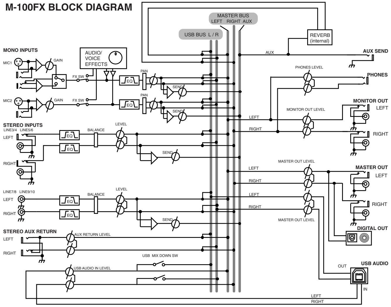
Block diagram
The following diagram shows the signal flow within the M-100FX.
flowchart
graph TD
    subgraph M-100FX_BLOCK_DIAGRAM
        direction TB
        A["MONO INPUTS"] --> B["MIC1"]
        A --> C["MIC2"]
        D["AUDIO/VOICE EFFECTS"] --> E["FX SW"]
        F["AUDIO/VOICE EFFECTS"] --> G["PAN"]
        H["AUDIO/VOICE EFFECTS"] --> I["SAND"]
        J["AUDIO/VOICE EFFECTS"] --> K["PAN"]
        L["AUDIO/VOICE EFFECTS"] --> M["SAND"]
        N["AUDIO/VOICE EFFECTS"] --> O["PAN"]
        P["AUDIO/VOICE EFFECTS"] --> Q["SAND"]
        R["AUDIO/VOICE EFFECTS"] --> S["PAN"]
        T["AUDIO/VOICE EFFECTS"] --> U["SAND"]
        V["AUDIO/VOICE EFFECTS"] --> W["PAN"]
        X["AUDIO/VOICE EFFECTS"] --> Y["SAND"]
        Z["AUDIO/VOICE EFFECTS"] --> AA["PAN"]
        AB["STEREO INPUTS"] --> AC["LINE3/4"]
        AB --> AD["LINE5/6"]
        AE["STEREO INPUTS"] --> AF["LEFT"]
        AE --> AG["RIGHT"]
        AH["STEREO AUX RETURN"] --> AI["LINE7/8"]
        AH --> AJ["LINE9/10"]
        AK["STEREO AUX RETURN"] --> AL["LEFT"]
        AK --> AM["RIGHT"]
        AN["STEREO AUX RETURN"] --> AO["LEFT"]
        AN --> AP["RIGHT"]
        AQ["STEREO AUX RETURN"] --> AR["LEFT"]
        AQ --> AS["RIGHT"]
        AT["STEREO AUX RETURN"] --> AU["LEFT"]
        AT --> AV["RIGHT"]
        AW["STEREO AUX RETURN"] --> AX["LEFT"]
        AW --> AY["RIGHT"]
        AZ["STEREO AUX RETURN"] --> BA["LEFT"]
        AZ --> BB["RIGHT"]
        BC["STEREO AUX RETURN"] --> BD["LEFT"]
        BC --> BE["RIGHT"]
        BF["STEREO AUX RETURN"] --> BG["LEFT"]
        BF --> BH["RIGHT"]
        BI["STEREO AUX RETURN"] --> BJ["LEFT"]
        BI --> BK["RIGHT"]
        BL["STEREO AUX RETURN"] --> BM["LEFT"]
        BL --> BN["RIGHT"]
        BO["STEREO AUX RETURN"] --> BP["LEFT"]
        BO --> BQ["RIGHT"]
        BR["STEREO AUX RETURN"] --> BS["LEFT"]
        BR --> BT["RIGHT"]
        BU["STEREO AUX RETURN"] --> BV["LEFT"]
        BU --> BW["RIGHT"]
        BX["STEREO AUX RETURN"] --> BY["LEFT"]
        BX --> BZ["RIGHT"]
        CA["STEREO AUX RETURN"] --> CB["LEFT"]
        CA --> CC["RIGHT"]
        CD["AUX"] --> DE["AUX BUS L/R"]
        DD["RANGE"] --> DE
        DE --> E
        DE --> F
        DE --> G
        DE --> H
        DE --> I
        DE --> J
        DE --> K
        DE --> L
        DE --> M
        DE --> N
        DE --> O
        DE --> P
        DE --> Q
        DE --> R
        DE --> S
        DE --> T
        DE --> U
        DE --> V
        DE --> W
        DE --> X
        DE --> Y
        DE --> Z
    end

    subgraph M-100FX_BLOCK_DIAGRAM
        direction TB
        A -- REVERB (internal) -- AUX -- AUX BUS_L/R -- AUX BUS_L/R -- AUX_BUS Right Aux
    end

    note1["MASTER BUS LEFT RIGHT AUX"]
    note2["PROHES LEVEL"]
    note3["MONITOR OUT LEVEL"]
    note4["MASTER OUT LEVEL"]
    note5["DIGITAL OUT"]
    note6["USB AUDIO"]
    note7["LEFT RIGHT"]
    note8["RIGHT RIGHT"]
    note9["LINK SWITCH"]
Basic operation
The M-100FX provides numerous connectors that can be connected to a wide variety of devices. This section explains how to connect the M-100FX with speakers, mics, audio devices, or your computer.
* To prevent malfunction and/or damage to speakers or other devices, always turn down the volume, and turn off the power on all devices before making any connections.
* Always make sure to have the volume level turned down before switching on power. Even with the volume all the way down, you may still hear some sound when the power is switched on, but this is normal, and does not indicate a malfunction.
* This section explains the devices that can be connected to the M-100FX, and any points of caution you must observe. For details on how you can use various combinations of connected devices, refer to Applications (p. 105).
Connecting monitor speakers or headphones
First we will connect equipment that will let you hear the sound.
Connect monitor speakers or headphones so that you can hear the sound you are mixing. Connect your monitor speakers to the monitor output jacks, or headphones to the headphone jack.

The monitor output jacks provide both phone type and RCA phono type connectors. The same signal is output from both types of connector. Use the connectors that are suitable for the cables you are using with your monitor speakers. If plugs are inserted into both the phone jacks and RCA phono jacks, sound will be output only from the phone jacks.
* Before you connect monitor speakers or headphones, turn the monitor volume knob or headphone volume knob, as well as the volume of your monitor speakers, all the way to the minimum position.
■ Adjusting the volume
- If you have connected monitor speakers, raise their volume to an appropriate level.
- Turn the monitor volume knob or headphone volume knob toward the right to adjust the volume as desired.
- Connecting a mic....(p. 20)
- Connecting audio devices ......(p. 23)
- Connecting the M-100FX to your computer ......(p. 25)
- Using the external input/output jacks (AUX)......(p. 28)
• Using the digital output jacks......(p. 30)
Connecting a mic
■ Connecting a mic to input audio
Mic input jacks 1 and 2 (INPUT 1, 2) can accept mics with either XLR plugs or phone plugs. The XLR jacks can provide phantom power for condenser mics that require it. The phone jacks can accept either balanced or unbalanced connections.
If you are using a condenser mic that uses phantom power, turn on the phantom power switch.
* You must leave the phantom power turned off unless you are using a condenser mic that requires phantom power. Malfunctions will occur if phantom power is supplied to a dynamic mic or an audio playback device. For details on the specifications of your mic, refer to the owner's manual supplied with your mic. (The M-100FX's phantom power supply is DC 48 V, 10 mA maximum.)

Before you connect a mic, turn the input level knob (GAIN) to the minimum position in order to protect the circuitry.

Phantom power
This is a method of supplying power for a condenser mic or similar device via the mic cable. The built-in phantom power supply provides 48 V (direct current). The shape of the plug is identical to that of a conventional XLR plug.
About balanced and unbalanced connections
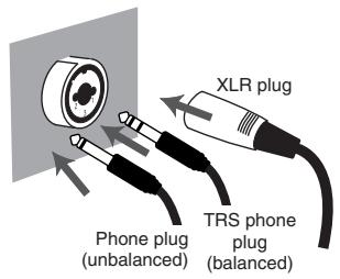


Balanced input is a method of transmitting a signal using three conductors, which are named "hot", "cold", and "ground". The plug is divided into three sections. Plugs used for stereo signals are divided into three sections in the same way, but are wired differently. Do not mix these two type of connections. Stereo signals cannot be input to mic input jack 1 or jack 2 (INPUT 1, 2).
Unbalanced input is the usual method of transmitting a signal using two conductors, a signal line and a ground. The plug is divided into two sections.
Types of mic
Mics can be broadly classified as either dynamic mics or condenser mics. The M-100FX can accept either type, and can also accept “plug-in powered mics”—the miniature condenser mics designed for connection to the mic jack of a computer or the recording jack of an MD (mini disc) recorder.
The plug-in powered mic jack accepts either monaural or stereo mics. If a stereo plug is connected to mic input jack 1 (INPUT 1), channel 1 will process the left/right signals in stereo. If a plug-in powered mic is connected, and you connect a mic to the XLR jack, no audio will be input from the mic connected to the XLR jack. Only the signal from the plug-in powered mic will be sent to the mixer.
If you are using the plug-in powered mic jack, the input level knob (GAIN) will not adjust the input level.

Only a plug-in powered mic can be connected to the plug-in powered mic jack. If a different type of mic, such a mic with a conventional stereo mini output plug is connected to this jack, the circuit may be damaged.
■ Adjusting the gain and level (volume)
After you have made connections, use the following procedure to adjust the volume appropriately.
-
Lower the input level knob (GAIN), master volume fader, monitor volume knob, and headphone volume knob to their minimum positions.
-
Adjust the gain.
While speaking/singing/performing into the mic, turn the input level knob toward the right for the channel to which your mic is connected. Adjust the input volume so it is as high as you can get it without causing the peak indicator to light.
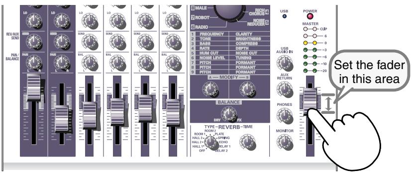
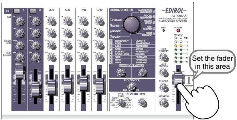
- Set the master volume fader to the center of the area shown in the panel illustration below.
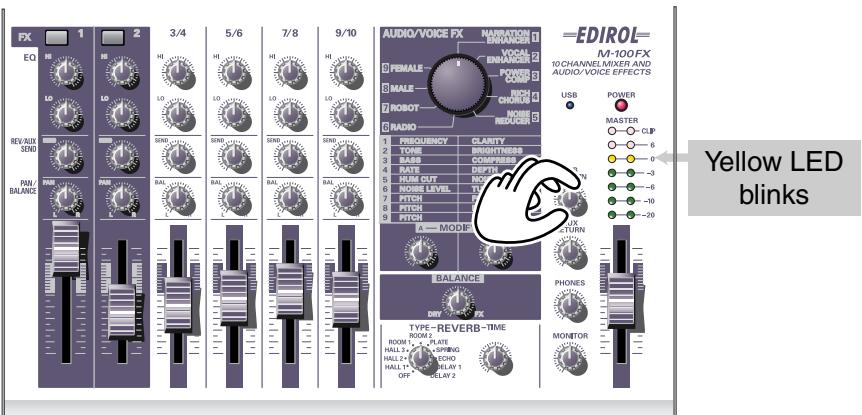
- Adjust the input level.
Adjust the input level fader so that the yellow LED (0 dB) of the master volume indicator lights occasionally.
If you are simultaneously recording with more than one mic, slowly raise the input level faders of all input channels to adjust their levels.
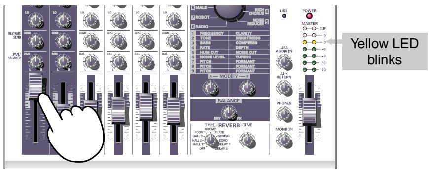

The peak indicator will light when the input signal level (volume) is excessive, indicating that the input signal is distorting. To obtain the best audio quality, you should set the input level as high as possible; i.e., raise the gain as high as possible without allowing the peak indicator to light.
Connecting audio devices
Here's how to make connections so you can sing along with a CD.
* For details on connecting a mic to input (record) your voice, refer to Connecting a mic (p. 20).
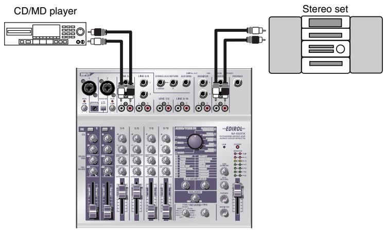
■ Connecting a stereo set or MD
The cables you connect to line input jacks 3/4 (LINE INPUT 3/4) and line input jacks 5/6 (LINE INPUT 5/6) can have either a phone plug or an RCA phono plug. If you connect both types simultaneously, only the sound from the phone plug connection will be sent to the mixer section.
■ Connecting the recording device
If you want to record the mixed signal, connect the M-100FX's master output jacks to the LINE IN or recording (REC) jacks of your cassette tape recorder or MD recorder.
The master output jacks provide both phone and RCA phono jacks. Both types output the same signal; use the type of jacks that match the cable connected to the recorder or other device you are using. If you connect both types simultaneously, only the sound from the phone plug connection will be sent to your recorder or other devices.
■ Adjusting the input level (volume)
After you have made connections, adjust the volume as follows
Set the input level faders and master volume fader to the minimum position. If you have connected monitor speakers or headphones, turn the monitor volume knob and headphone volume knob to the minimum position.
MEMO
Each of the line inputs 3/4, 5/6, 7/8, 9/10 (LINE INPUT 3/4, 5/6, 7/8, 9/10) have the very same circuitry. Use them as desired, according to the order of the devices you are connecting, or the location of the devices.
MEMO
The phone type and RCA phono type input jacks for the line inputs are connected to the same circuitry within the M-100FX. Use the connector that is appropriate for your cable.
NOTE
Before you connect an audio device to a jack, turn the master volume fader and input level fader to the minimum position in order to protect the circuitry.
MEMO
For details on adjusting the mic input level, refer to Connecting a mic (p. 20).
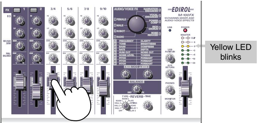
- Set the master volume fader to the position indicated by the black marking on the panel.
- Produce sound on the device connected to the line input jacks.
Slowly raise the input level fader to increase the level. Set the level so that the yellow indicator (0 dB) of the master volume indicator lights occasionally. If you have connected devices to more than one line input jack (channel) and want to record them, raise the input level faders for each input channel you are using, and adjust them as desired.
- If your recording device allows you to adjust the recording level, adjust the level so that the peak indicator of your recording device does not light, or so that the level meter stays within the appropriate recording level.
- If you have connected monitor speakers, raise the volume of your monitor speakers to an appropriate level.
- Turn the monitor volume knob or headphone volume knob to the desired volume.
Connecting the M-100FX to your computer
The M-100FX has a USB connector that lets you connect it to your personal computer. If the M-100FX is connected to your computer via a USB cable, the audio signal (sound) output from your computer can be mixed with the audio signals that are being input into the M-100FX, or the signals (sounds) mixed by the M-100FX can be sent to your computer.
The sounds mixed or processed by the M-100FX's effects can also be recorded into music production software or waveform editing software on your computer to create your own original audio data.
What is USB?
USB stands for Universal Serial Bus, and is an interface that lets you connect a variety of peripheral devices to your computer. A single USB cable can connect many different kinds of devices, and convey data at high speed.
You can also connect or disconnect peripheral devices without having to turn off the power first, and your computer will automatically detect the device that you connected. Some devices may require you to make settings or perform other procedures.
You computer will detect the M-100FX as a device used to transfer audio signals to and from the computer.
* The M-100FX supports USB Version 1.1.
In order to use the M-100FX via its USB connector, you must install a driver in your computer. For details on installing the driver, refer to Connecting the M-100FX to your computer (p. 124).
Install the driver as described in Connecting the M-100FX to your computer (p. 124).
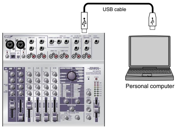
To record audio into your computer, make connections as shown in the diagram below.
Connect the USB cable to the USB connector on the back of the M-100FX. For details on connecting your monitor speakers or headphones, refer to Connecting monitor speakers or headphones (p. 19).
NOTE
If you are using Windows and want to send the playback of an audio CD to the M-100FX via USB, you will need to use Windows Media Player 7 or later. If you are using Advanced mode on Mac OS9, you cannot send the playback audio from a music CD to the M-100FX.
MEMO
For details on connecting a mic to input your voice, refer to Connecting a mic (p. 20).
■ Adjusting the input level (volume)
After you have made connections, here's how to adjust the volume appropriately for recording.
Set the input level faders, master volume fader, and USB input level knob to their minimum positions. If you have connected headphones, set the headphone volume knob to the minimum position.
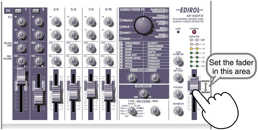
1. Set the master volume fader to the middle of the area indicated in black on the panel.
2. While playing back audio on your computer, slowly turn the USB input level knob toward the right to increase the level. Set the level so that the yellow LED (0 dB) of the master volume indicator lights occasionally.
If you have connected devices to more than one line input jack (channel) and want to record them, raise the input level faders of all these channels to adjust their levels.
3. If you are recording the audio signal on your computer, make adjustments in your software so that the recording level is appropriate.
The master volume fader adjusts the volume of the audio that is sent from the M-100FX's USB connector to your computer.
MEMO
For details on adjusting the mic input level, refer to Connecting a mic (p. 20).
MEMO
If you are inputting (recording) audio into your computer, it is a good idea to make a note of the position of the USB input level knob. You may need to turn down the USB input level knob while recording.
* Depending on your recording software, the signal that is being input for recording may be sent directly back to the USB audio output. In this case, a feedback loop will occur with the M-100FX's USB audio input, possibly producing a squealing noise or distortion. To prevent this, you can either set your recording software to stop outputting to USB, or turn the M-100FX's USB input level knob all the way to the left (the 0 position).
* The master volume fader controls the volume of the digital output and the level (volume) at which the mixed signal is sent to USB. If you want to adjust the volume of your monitor speakers independently of the recording level, connect your monitor speakers to the M-100FX's monitor output jacks (analog) and use the monitor output knob to adjust the volume.
Using the external input/output jacks (AUX)
The external output jack (AUX SEND) outputs the sound adjusted by the REVERB/AUX send level knobs of each channel. The signal sent from the external output jack (AUX SEND) is monaural.
The external input jacks (AUX RETURN) are supplementary inputs for sound from an external device. Use these jacks when you are using an external effects processing device to process the sound sent from the external output jack (AUX SEND) and return the processed sound back to the M-100FX. Alternatively, you can connect any external device to these jacks in the same way as to the line inputs.
The AUX input level knob adjusts the volume of the audio signal received at the external input jacks (AUX RETURN).
* Before you connect a device to the external input/output jacks, turn the reverb/AUX send level knobs (REV/AUX SEND) of each channel and the AUX input level knob all the way to the left (minimum) in order to protect the circuitry. When you are finished making connections, gradually turn the knobs toward the right. Here are some ways in which you can use these jacks.
- Send the external output jack (AUX SEND) output to an effects processing device, and send the processed signal back to the M-100FX's external input jacks (AUX RETURN).
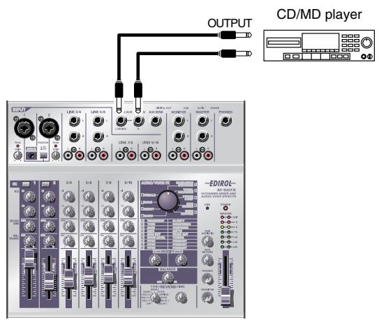
- Input sound from a CD player or other external device into the M-100FX's external input jacks (AUX RETURN).

If the input of each channel is stereo, the volume may be significantly different than the original signal. This is due to the conversion of the stereo signal into mono, and is not a malfunction.
- Independently listen to the sound of a specific channel.
Turn the reverb/AUX send level knob (REV/AUX SEND) of the channel that you want to hear toward the right, and turn the reverb/AUX send level knob (REV/AUX SEND) of the other channels all the way toward the left. This lets you listen only to the sound of the desired channel.
* If the reverb type select knob is not turned OFF, the same signal as sent from the external output jack (AUX SEND) will also be sent to the internal reverb. If you don't need to apply the internal reverb, turn the reverb type select knob to OFF.
* In order to connect a CD player or similar device to the external input jacks (AUX RETURN), you may need an adaptor to convert the RCA phono connection (typically found on a CD player) to a phone plug. If you have any unused line input jacks, we suggest that you connect your device to the line input jacks.
Using the digital output jacks
The M-100FX provides two types of digital output jack; OPTICAL and COAXIAL. These two jacks output the same signal (sound). Use the jack that is appropriate for the cable and device you are connecting.
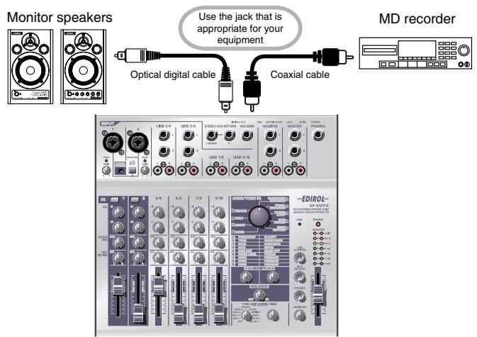
■ Connecting monitor speakers that have digital input jacks
If your monitor speaker system has a digital input jack, you can connect it to the digital output jack located on the rear panel of the M-100FX. Since the signal is sent in digital form to your monitor speakers, the signal will experience less degradation and noise.
Use the master volume fader to adjust the volume. This allows you to adjust the volume even if your monitor speakers cannot adjust the volume of a digital input signal.
■ Connecting an MD recorder
If you want to record the sound mixed by the M-100FX onto your MD or DAT recorder, connect your MD recorder to the M-100FX's digital output jack.
Use the master volume fader to adjust the volume.

The sampling frequency is 44.1 kHz.

Before you make connections, turn down the monitor level knob and headphone volume knob to the minimum position in order to protect the circuitry. If monitor speakers are connected, turn down the speaker volume as well.
What are the audio/voice effects?
You can apply audio/voice effects to mic input jacks 1 and 2 (CH 1, 2). These effects use an internal digital signal processor (DSP) to process the sound from your mic(s) in a variety of ways, such as boosting the low-frequency range, giving the sound greater clarity, or changing the pitch.
How to apply effects
For details on connecting mics or other devices, refer to the explanations in Basic operation (p. 19).
- For the channel to which your mic is connected, press the effect switch to turn it on. It will light in red.
- Use the audio/voice effect select knob to select an effect.
- Use effect modify knobs A/B to adjust the character (parameters) of the effect.
- Use the effect balance knob to adjust the depth of the effect, or the proportion of the original sound and processed sound.
Effect types
| 1 | NARRATION ENHANCER | (p. 33) | ||
| Makes narrations or announcements sound clearer. Removes unwanted noises. | A | FREQUENCY | ||
| B | CLARITY | |||
| 2 | VOCAL ENHANCER | (p. 33) | ||
| Adjusts the tonal character of the voice to give it range and brightness. Conversely, you can make the character more subdued. | A | TONE | ||
| B | BRIGHTNESS | |||
| 3 | POWER COMPRESSOR | (p. 34) | ||
| Adds power to a voice that lacks strength in the low-frequency region. Can also be used to boost a voice that tends to be drowned out by other sounds. | A | BASS | ||
| B | COMPRESS | |||
| 4 | RICH CHORUS | (p. 34) | ||
| Gives spaciousness and depth to the sound. Raising the Balance knob will add a sense of modulation, producing a mysterious effect. | A | RATE | ||
| B | DEPTH | |||
| 5 | NOISE REDUCER | (p. 35) | ||
| Reduces electronic hum and hiss noise. | A | HUM CUT | ||
| B | NOISE CUT | |||
| 6 | RADIO | (p. 35) | ||
| Simulates the noise that is often produced by a radio or analog record, creating the sensation of an old recording. | A | NOISE LEVEL | ||
| B | TUNING | |||
| 7 | ROBOT | (p. 36) | ||
| Gives the sound a robotic feel, with little change in pitch. | A | PITCH | ||
| B | FORMANT | |||
| 8 | MALE | (p. 36) | ||
| Transforms a female voice into a male voice. | A | PITCH | ||
| B | FORMANT | |||
| 9 | FEMALE | (p. 37) | ||
| Transforms a male voice into a female voice. | A | PITCH | ||
| B | FORMANT | |||
■ Effect parameters
1. NARRATION ENHANCER
This effect makes a voice sound clearer. It also reduces the unwanted sibilant noise from a mic input, making the sound easier to listen to. You can use this when adding announcements, narrations, or readings to the video you are editing.
A. FREQUENCY
Effect knob A specifies the frequency region in which the clarity of the voice will be adjusted by knob B. As you turn effect knob A toward the right, the effect will be applied to a broader region.
B. CLARITY
This adjusts the strength with which the voice will be clarified. As you turn effect knob B toward the right, a stronger effect will be applied. If you apply an excessive amount of this effect to a voice that is already clear, the sound will become harsh or distorted.
2. VOCAL ENHANCER
This effect boosts or reduces the components of a sound that produce its basic character. You can use this to emphasize or correct the character of a voice when recording dialog or a song.
A. TONE
Turning effect knob A toward the right will boost the frequency region that contains the fundamental portion of the voice, giving it greater richness. If you want to make the sound less resonant and rich, turn the knob toward the left.
B. BRIGHTNESS
Effect knob B boosts the frequency region that makes a voice distinctive. Turn the knob toward the right to emphasize breath noises and expression, or toward the left to tame a harsh-sounding voice.

Sibilant: the noise that can occur when words having an “s” or “sh” sound are pronounced.
3. POWER COMPRESSOR
This effect can boost a thin voice that has insufficient low range, giving it more power. It can also give consistency to a voice that varies widely in volume, or give more prominence to a voice that tends to be obscured by other sounds.
If the volume is already sufficient and there are no other sounds that obscure the voice, avoid applying this effect excessively. Doing so may increase the noise, or suppress loud sounds, making the sound muffled.
A. BASS
This boosts or suppresses the low-frequency region of the voice. Turning effect knob A toward the right will produce a stronger emphasis. You can use this to augment the low frequencies for a voice that was recorded at a distance away from the mic.
B. COMPRESS
This reduces the volume difference between loud and soft sounds, raising the overall volume. As you turn effect knob B toward the right, sounds will tend to be adjusted to a higher level. Unlike simply increasing the volume, this prevents high-volume sounds from distorting.
4. RICH CHORUS
This effect adds a “chorus” effect produced by adding a pitch-modulated sound to the original sound, creating a spacious sensation. It can be used to produce fantasy-like effects that have a reduced sense of direction, or to add the impression of a backing chorus to vocal harmony.
A. RATE
Adjusts the rate of modulation. Turning effect knob A toward the right will produce faster modulation.
B. DEPTH
Adjusts the depth of modulation. Turning effect knob B toward the right will produce deeper changes in the pitch and volume, creating a more intense modulation effect.
Generally, the modulation rate can be set to a fairly slow speed, and if you want to add the feeling of a backing chorus, set the modulation depth to a setting only slightly to the left of center. Use deeper settings if you want to create a spacious, fantasy-like effect.

If the input sound is too low in volume, the effect will not be strong. Make the input sound louder.
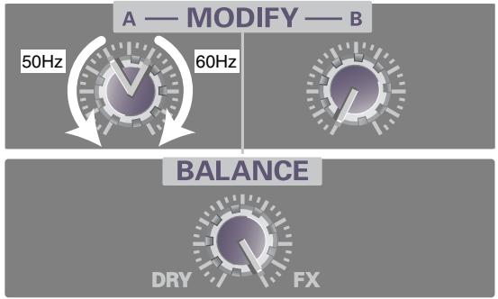
5. NOISE REDUCER
This reduces “hiss” noise and the buzzing “hum” that is sometimes produced by electronic equipment.
This is an effective way to remove noise that occurs at a specific frequency, or to remove noise that occurs at a lower level than the voice.
A. HUM CUT
This selects either 50 Hz or 60 Hz as the frequency of the hum that will be removed. Set this to match the frequency of the electrical power in your area.
Turning effect knob A toward the left of center will cut 50 Hz hum. Turning the knob toward the right of center will cut 60 Hz hum. Hum will be cut more deeply as you turn the knob further away from the center, but this will also affect the tone of the audio signal, and may cause other undesired effects such as distortion.
B. NOISE CUT
This cuts the background noise that is heard when the voice is silent. The noise will be cut more significantly as you turn effect knob B toward the right.
If this setting is excessive, the beginning and end of your vocal phrases will be cut off unnaturally, and it may become difficult to understand the voice.
6. RADIO
This effect adds the noises characteristic of AM radio to the voice, producing the impression of a radio broadcast or an old recording.
A. NOISE LEVEL
Adjusts the volume of the AM radio noise. Turning effect knob A toward the left will increase the volume of the noises produced when the radio is tuned inaccurately.
B. TUNING
Simulates the sounds that occur when you tune the frequency of a radio. The simulated tuning will be “correct” when effect knob B is in the center position. Turning the knob to left or right will make the simulated tuning drift, roughening the sound.
7. ROBOT
This effect fixes the frequency of the voice at a single pitch, giving the voice a robotic character. You can use this to give a mechanical character to spoken words.
A. PITCH
Robot Voice fixes the pitch of the voice at a specific frequency. Effect knob A sets the pitch level. Turning the knob toward the right will raise this fixed pitch.
B. FORMANT
"Formants" are features of a voice that determine its character. Effect knob B adjusts the formants. Turning the knob toward the left will produce a low, heavy voice (as if the vocal cords were larger), and turning the knob toward the right will produce a high, thin voice (as if the vocal cords were smaller).
8. MALE
By modifying the pitch and formants of the voice, this effect transforms a female voice into a male voice.
This is convenient when you are recording a dialog or dramatic presentation by yourself. By setting the effect balance knob near the center, you can mix the modified sound with the original sound, producing the impression of a duet.
By applying this effect to an actual male voice, you can produce an even deeper and bigger voice.
A. PITCH
Adjusts the amount by which the pitch will be shifted. As you turn effect knob A toward the left, the pitch of the voice will be lowered. If the knob is turned all the way toward the right, the voice will be at the original pitch.
B. FORMANT
"Formants" are features of a voice that determine its character. Effect knob B adjusts the formants. Turning the knob toward the left will produce a deeper voice (as if the vocal cords were larger). If the knob is turned all the way toward the right, the formants will be as in the original voice.

If you apply this effect excessively, the sound may crack or distort.

You should input the voice of only one person. The clearer the original voice, the better the effect will be. The effect will not be satisfactory if the voice being input is too soft, or if more than one person is speaking, or if there is excessive background noise.

Formants These are fixed frequency regions in which the sound of a voice is emphasized, thus determining its basic character. The location and size of the formants depends on the size of the vocal cords, and differs between men and women, adults and children.

If you apply this effect excessively, the sound may crack or distort.

You should input the voice of only one person. The clearer the original voice, the better the effect will be. The effect will not be satisfactory if the voice being input is too soft, or if more than one person is speaking, or if there is excessive background noise.
9. FEMALE
By modifying the pitch and formants of the voice, this effect transforms a male voice into a female voice.
This is convenient when you are recording a dialog or dramatic presentation by yourself. By setting the effect balance knob near the center, you can mix the modified sound with the original sound, producing the impression of a duet.
By applying this effect to an actual female voice, you can produce a thinner and more delicate voice.
A. PITCH
Adjusts the amount by which the pitch will be shifted. As you turn effect knob A toward the right, the pitch of the voice will be raised. If the knob is turned all the way toward the left, the voice will be at the original pitch.
B. FORMANT
"Formants" are features of a voice that determine its character. Effect knob B adjusts the formants. Turning the knob toward the right will produce a more shrill voice (as if the vocal cords were smaller). If the knob is turned all the way toward the left, the formants will be as in the original voice.

If you apply this effect excessively, the sound may crack or distort.

You should input the voice of only one person. The clearer the original voice, the better the effect will be. The effect will not be satisfactory if the voice being input is too soft, or if more than one person is speaking, or if there is excessive background noise.


When sound is produced in a building such as a concert hall or auditorium, the sound reflects from the walls and ceiling of the room and reaches the listener at a later time. This is called reverberation, usually abbreviated as “reverb”.
The character of reverb depends on the size of the space (hall, room, etc.), its shape, and the materials of the reflective surface (walls, etc.). The M-100FX can digitally simulate these aspects of reverb, and add the reverb to the original sound. This type of processing is referred to as “digital reverb”.
How to apply reverb
For details on connecting your mic and other equipment, refer to Basic operation (p. 19).
- Use the reverb type select knob to select the desired reverb type.
- Turn the reverb/AUX send level knob to adjust the reverb depth.
- Use the reverb time knob to adjust the length of the reverb.
HINT
Direct sound: Sound that reaches the listener directly from the sound source.
Early reflections: Sound that reaches the listener after being reflected once.
Late reverberation: Sound that reaches the listener after being reflected multiple times.
NOTE
Reverb is not applied to sound that is input from the computer via USB, nor to the sound that is input from the external input jacks (AUX RETURN).
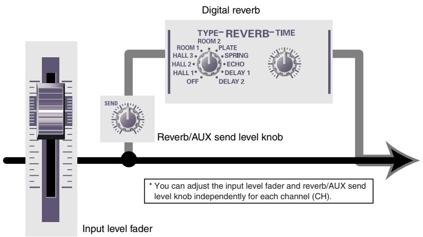
How digital reverb works
flowchart
graph LR
    A["Input level fader"] --> B["Reverb/AUX send level knob"]
    B --> C["TYPE-REVERB-TIME ROOM 2"]
    C --> D["Digital reverb"]
    D --> E["SEND"]
    E --> A
    note1["• You can adjust the input level fader and reverb/AUX send level knob independently for each channel (CH)."]
- The reverb/AUX send level knob of each channel adjusts the amount of sound that is sent to the digital reverb.
Turning a reverb/AUX send level knob toward the right will make the reverb deeper for that channel.
- The digital reverb processes the sound to produce the impression of a large hall or club.
You can use the reverb type select knob and reverb time knob to adjust the digital reverb. The reverb type select knob lets you choose one of ten types of reverberation. The reverb time knob adjusts the length of the reverb and the spacing of the early reflections. Turning the reverb time knob toward the right will lengthen the reverb time. If you switch the reverb type, the reverb time will be set to the default setting for that type, regardless of the actual position of the reverb time knob. The default setting for the reverb time is the center position of the reverb time knob.
■ Reverb types
| Type | Effect |
| OFF | No reverberation will be applied.Select this setting if you don’t want to apply an effect. |
| HALL 1, 2, 3 | Simulates the reverberation of a spacious room such as a concert hall or gymnasium. |
| ROOM 1, 2 | Simulates the reverberation of a room such as a club or disco. |
| PLATE | Simulates the artificial reverberation produced by a plate reverb (a reverb unit using a metal plate). It produces denser reverberation than HALL or ROOM. This is particularly suitable for vocals. |
| SPRING | Simulates the artificial reverberation produced by a spring reverb (a reverb unit using a metal spring). It produces a distinctive “sproing” effect. |
| ECHO | Produces individually identifiable echoes. Reducing the delay time will create the echo effect typical of karaoke mics. |
| DELAY 1, 2 | By adding a slightly delayed sound to the original sound, this produces a distinctive effect of greater depth. DELAY 2 is a special delay in which the sound alternates between left and right, and can be used to produce a disorienting sensation. This is effective when used with a stereo connection. |
■ Reverb time
Turning the reverb time knob toward the right will lengthen the reverberation.
The default value is the setting when the reverb time knob is at the center position.
Applications
“Mixing” is the process of adjusting the volume, tone, and pan of each channel to create the overall balance. In an actual recording studio, mixing consoles with many faders and knobs are used to adjust the volume balance of each channel and apply effects.
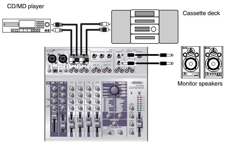
The basic function of the mixer is to mix together a variety of audio sources such as sound from the mics, audio from the video tape, CD, and cassette tape to combine them into a final mix.
As an example, here's how to mix the sounds from a music CD and a cassette tape.
- Turn the input level knobs (GAIN), master volume fader, monitor volume knob, and headphone volume knob to their minimum positions.
- Connect your CD player to line input jacks 3/4 (CH 3/4).
- Connect your cassette tape recorder to line input jacks 5/6 (CH 5/6).
Adjust the volume of the cassette tape recorder.
- Connect your monitor speakers to the monitor output jacks. Alternatively, connect your headphones to the headphone jack.
Now you can hear the sound you will be mixing.
Adjust the following volumes.
Headphones...... Headphone volume knob
Monitor speakers...... Monitor volume knob
- If you want to record the sound you are mixing, connect your recording device to the master output jacks or the digital output jack.
- Use the input level faders of each channel to adjust the volume.
Raising the input level fader will increase the volume, and lowering it will decrease the volume. Adjust the input level faders of each channel to create an appropriate balance.
You can slowly raise a fader upward from the minimum position to create a “fade-in”, or slowly lower a fader to the minimum position to create a “fade-out”.
You can create natural-sounding transitions between sounds by fading-in and fading-out.

In this example, you can create a gradual transition from the sound of the CD to the sound of the cassette tape by fading-in CH 3/4 while fading-out CH 5/6.
7. Use the equalizer (EQ) HI/LO knobs of each channel to adjust the tone.
Turning the equalizer (EQ) HI knob toward the right will emphasize the high-frequency portion of the sound, and turning it toward the left will de-emphasize this range.
Turning the equalizer (EQ) LO knob toward the right will emphasize the low-frequency portion of the sound, and turning it toward the left will de-emphasize this range.
| Effect | Operation |
| To make the CD sound more powerful | Turn the equalizer (EQ) LO knob toward the right |
| To make the CD sound more brilliant | Turn the equalizer (EQ) HI knob toward the right |
| To minimize the “hiss” noise of a cassette tape | Turn the equalizer (EQ) HI knob toward the left |
| To minimize the background noise entering a mic | Turn the equalizer (EQ) LO knob toward the left |
8. If you are recording, use the master volume fader to adjust the volume.
You can create a fade-in by slowly raising the fader upward from the minimum position, or a fade-out by slowly lowering the fader down to the minimum position.

It is effective to use a fade-in when you start recording, and a fade-out when you finish recording.
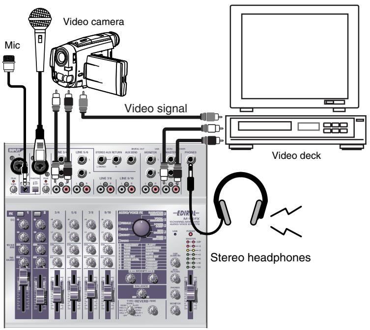
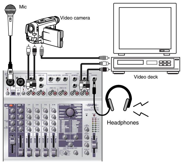
Using the NARRATION ENHANCER
Here's a typical example of how you can use a mic to add realtime commentary to video that you recorded, and re-record the video and sound on another video deck.
-
Turn all input level knobs and input level faders down to the minimum position, and connect your monitor speakers or headphones.
(→Connecting monitor speakers or headphones (p. 19)) -
Connect the audio output of your video camera to the M-100FX's line input jacks 3/4.
Audio output is usually the red and white plugs.
- Connect the video output of your video camera to the video input jack of your video deck.
Video is usually the yellow plug.
- Connect the M-100FX's master output jacks to the line input jacks of your video deck.
If you want to adjust the audio from your video camera, use the CH 3/4 input level fader to adjust the input level.
-
Connect your mic to mic input jack 1 (CH1), and adjust the gain and level. ( Connecting a mic (p. 20))
-
Make effect settings. In this example, we'll use the [1] NARRATION ENHANCER effect, which is particularly suitable for narrations.
-
Press the CH 1 effect switch to turn it on. It will light in red.
-
Turn the audio/voice effect knob to [1] NARRATION ENHANCER.
MEMO
If your cable has a different type of plug, you may need to obtain an adaptor plug or a different cable.
HINT
Equalizer LO knob
Turning this toward the left of center will reduce breath noise, making the sound more listenable.
Reverb/AUX send level knob
Turn this all the way to the left and no reverb will be applied, thus preserving the clarity of the voice.
Immediately after you have set the audio/voice effect knob to [1] NARRATION ENHANCER, the effect will have the default settings (see diagram below, or p. 113) regardless of the actual positions of effect knobs A and B and the effect balance knob.
Default settings for [1] NARRATION ENHANCER

Other effects can also be used to modify the character of the voice. For details on each effect, readEffect types (p. 32). You can also try out many other possibilities as described in Effect applications (p. 113).
- Set effect knobs A and B and the effect balance knob to the default positions shown in the diagram above.
- While you speak into the mic, slowly adjust effect knobs A and B to adjust the effect to your liking. You may wish to practice your narration while watching the actual video.
- Begin editing your video while you add the narration. You will probably want to use the following procedure.
Start recording on your video deck ↓
Start playback on your video camera ↓
Start recording your narration

The sound will become clearer as you turn effect knob A and effect knob B toward the right. For details on effects, refer to Effect types (p. 32).

For details on operating your video camera and video deck, refer to the owner's manual for your device.
Singing
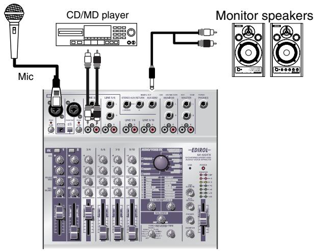
Here's how you can use two mics to sing along with a CD.
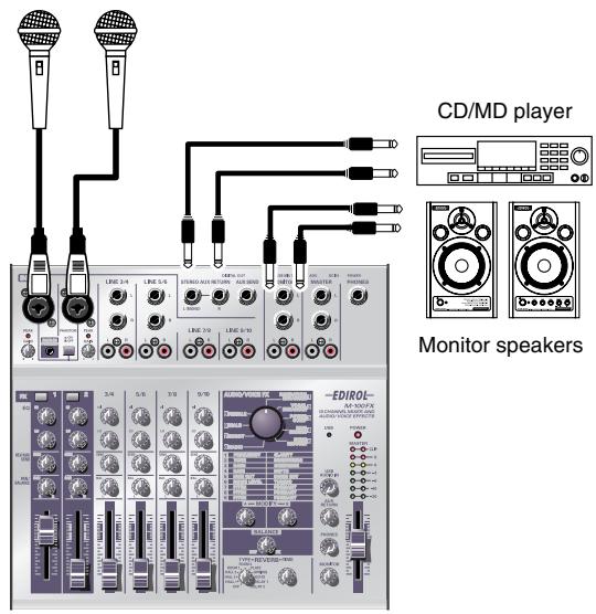
- Turn the AUX input level knobs to the minimum positions, and then connect your monitor speakers.
(→Connecting monitor speakers or headphones (p. 19)) - As shown in the diagram, connect your CD player to the external input jacks (AUX RETURN).
The external input jacks (AUX RETURN) accept phone plugs. If your cable has a different type of plug, you will need an adaptor. - While playing back the CD, slowly turn the AUX input level knob toward the right to adjust the sound from your monitor speakers to an appropriate volume.
- Connect a mic to mic input jack 1 (CH 1) and adjust the gain and level. (→Connecting a mic (p. 20))
-
Adjust the reverb. Applying reverb to a karaoke vocal will create a pleasing effect. In this example, we'll use HALL 1 to give a spacious presence to the vocal.
-
Set the reverb type select knob to HALL 1.
-
Use the reverb/AUX send level knobs of CH1 and CH2 to adjust the amount of reverb applied to each mic.
-
Use the pan/balance knobs to adjust the pan of each mic.
For a duet, it is effective to set CH1 to the left and CH2 to the right.
- Play back the CD, and sing into the mics.

The effect will depend on the type of reverb you select. Refer to Reverb types (p. 103) and try out various types of reverb.

If you are inputting a sound that does not require processing, such as that from a CD, you may find it convenient to connect it to the external input jacks (AUX RETURN) so that you can adjust the input volume simply by turning the AUX input level knob. Of course you can also connect it to the line input jacks and use the input level fader and knobs to adjust the volume.

Equalizer LO knob
Turning this toward the left of center will reduce breath noise, making the sound easier to listen to.
Reverb/AUX send level knob
Rather than turning the knob all the way to the left, setting it to a position of approximately the first mark will add a small amount of reverb, giving a nice amount of luster to the sound.
Removing noise
Sound that was recorded outdoors may contain unwanted noises. Here's how you can minimize such unwanted noises.
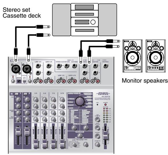
-
Turn the input level knob and all input level faders to the minimum position, and connect your monitor speakers and headphones.
(→Connecting monitor speakers or headphones (p. 19)) -
As shown in the diagram, connect your cassette deck to the CH1 and CH2 mic input jacks (INPUT 1, 2). Connect the left channel of the cassette deck to CH1, and the right channel to CH2.
-
Adjust the gain and level. (→Adjusting the gain and level (volume) (p. 22))
-
Simultaneously press the effect switches of CH1 and CH2 to select Stereo Control.
Stereo Control
Simultaneously pressing the CH1 and CH2 effect switches will select Stereo Control. In this state, the CH1 and CH2 effect switches will both light in red.

If you have selected Stereo Control, operating the CH1 input level fader or knobs will control both the left channel (CH1) and right channel (CH2) simultaneously. Nothing will happen when you operate the CH2 input level fader or knobs.
If you want to make additional adjustments to the sound, use the CH1 input level fader or knobs.
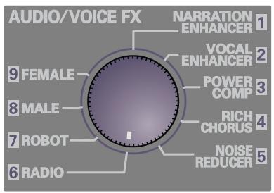
-
Set the audio/voice effect knob to [5] NOISE REDUCER.
-
Set effect knob A to the center position.
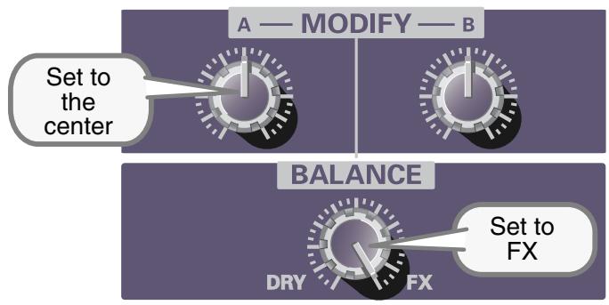
- Turn the effect balance knob all the way toward FX (right).
- Play back your cassette tape, and move effect knob B. Set effect knob B to the point at which the noise is removed from silent portions of the program material.

Be aware that if you turn effect knob B too far toward the right, even desired sounds may disappear.
Effect applications
This section describes various ways in which you can set effect knobs A and B and the effect balance knob for different applications.
For details on the effect types and what they do, refer to Audio/Voice effects (p. 31).
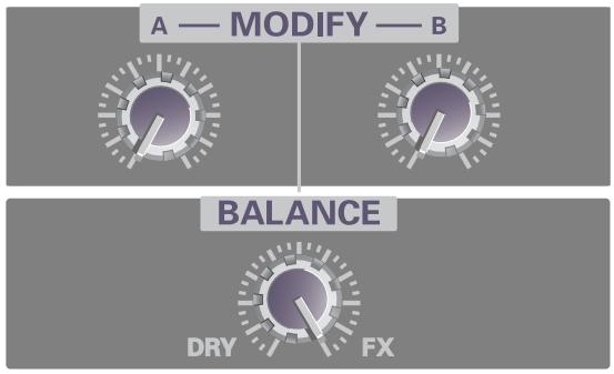
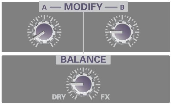
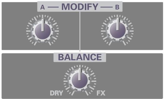
1. NARRATION ENHANCER
■ Default settings
These settings clarify a narration or announcement, making it more listenable, while removing unpleasant noises.
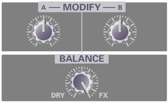
flowchart
graph TD
    A["A — MODIFY — B"] --> B["Balance"]
    B --> C["DRY"]
    B --> D["FX"]
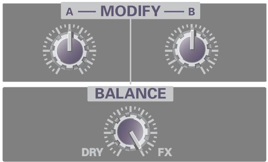
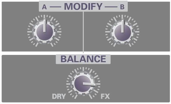
■ Removing only unpleasant noises
With these settings, the clarity of the voice will not be affected; only unpleasant sibilants and other noises will be removed.
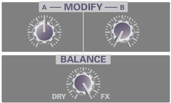
flowchart
graph TD
    A["A — MODIFY — B"] --> B["BALANCE"]
    B --> C["DRY"]
    B --> D["FX"]
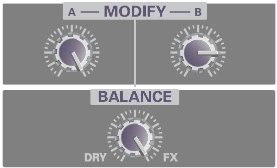
2. VOCAL ENHANCER
■ Default settings
These settings emphasize the fundamental portion of a voice and its distinctive attributes, giving the sound brightness and depth.
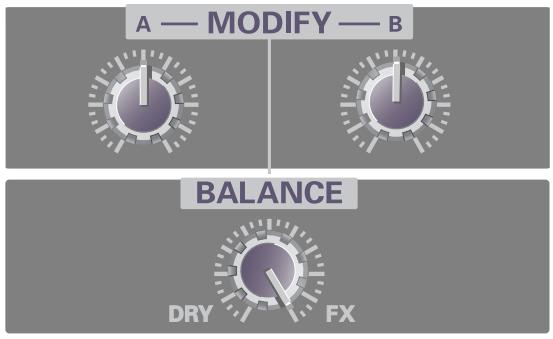
flowchart
graph TD
    A["MODIFY"] --> B["BALANCE"]
    B --> C["DRY"]
    B --> D["FX"]
■ Reducing the obtrusiveness of the voice
These settings restrain the fundamental portion of a voice and its distinctive attributes, making the sound less obtrusive.
flowchart
graph TD
    A["A — MODIFY — B"] --> D1["DRY"]
    A --> D2["FX"]
3. POWER COMP
■ Default settings
These settings boost a voice that is weak in the low range, and smooth out variations in volume to make the level more consistent and powerful.
flowchart
graph TD
    A["A — MODIFY — B"] --> B["Balance"]
    B --> C["DRY"]
    B --> D["FX"]
■ Creating a more powerful voice
These settings give more power to the low-frequency region, creating a more powerful sound. Applying these settings to music that already has a substantial low-frequency component can give the sound chest-thumping impact.
flowchart
graph TD
    A["A — MODIFY — B"] --> B["Balance"]
    B --> C["DRY"]
    B --> D["FX"]
4. RICH CHORUS
■ Default settings
These settings give the sound more spaciousness and depth.
flowchart
graph TD
    A["A — MODIFY — B"] --> B["Balance"]
    style A fill:#f9f,stroke:#333
    style B fill:#bbf,stroke:#333
    note1["DRY"] --> B
    note2["FX"] --> B
■ Adding light spacious to the sound
These settings lightly apply a slow chorus sound to create a subtle spaciousness. This is effective on backing chorus or scat singing.
flowchart
graph TD
    A["MODIFY"] --> B["BALANCE"]
    B --> C["DRY"]
    B --> D["FX"]
■ Creating a distinctive modulation effect
These settings add a greater sense of modulation to the chorus effect, producing a dramatic effect. This is effective with jingles.
flowchart
graph TD
    A["A — MODIFY — B"] --> B["BALANCE"]
    B --> C["DRY"]
    B --> D["FX"]
5. NOISE REDUCER
■ Default settings
These settings cut the noise during silent portions of the program. If you want to cut the noise to a greater extent, turn effect knob B toward the right. If a portion of the desired sound is being cut, turn effect knob B toward the left.
flowchart
graph TD
    A["A — MODIFY — B"] --> B["Balance"]
    B --> C["DRY"]
    B --> D["FX"]
■ Removing hum noise
These settings cut the buzzing hum noise produced by electronic devices. If the electrical power in your area is 50 Hz, turn the knob toward the left to cut the hum. If your electrical power is 60 Hz, turn the knob toward the right.
6. RADIO
■ Default settings
These settings simulate the muffled sound produced by a radio.
flowchart
graph TD
    A["A — MODIFY — B"] --> B1["Control knob 1"]
    A --> B2["Control knob 2"]
    A --> B3["Control knob 3"]
    B1 --> C1["DRY"]
    B2 --> C2["FX"]
    B3 --> C3["DRY + FX"]
■ Simulating the sound of an old radio
These settings simulate the effect of speech heard through an old radio that is mistuned.
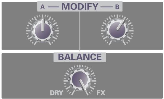
flowchart
graph TD
    A["A — MODIFY — B"] --> B1["Black Circle"]
    B1 --> C1["White Circle"]
    C1 --> D1["Gray Circle"]
    D1 --> E1["White Circle"]
    E1 --> F1["Gray Circle"]
    F1 --> G1["White Circle"]
    G1 --> H1["Gray Circle"]
    H1 --> I1["White Circle"]
    I1 --> J1["Gray Circle"]
    J1 --> K1["White Circle"]
    K1 --> L1["Gray Circle"]
    L1 --> M1["White Circle"]
    M1 --> N1["Gray Circle"]
    N1 --> O1["White Circle"]
    O1 --> P1["Gray Circle"]
    P1 --> Q1["White Circle"]
    Q1 --> R1["Gray Circle"]
    R1 --> S1["White Circle"]
    S1 --> T1["Gray Circle"]
    T1 --> U1["White Circle"]
    U1 --> V1["White Circle"]
    V1 --> W1["Gray Circle"]
    W1 --> X1["White Circle"]
    X1 --> Y1["Gray Circle"]
    Y1 --> Z1["White Circle"]
    Z1 --> AA1["Gray Circle"]
    AA1 --> AB1["White Circle"]
    AB1 --> AC1["Gray Circle"]
    AC1 --> AD1["White Circle"]
    AD1 --> AE1["Gray Circle"]
    AE1 --> AF1["White Circle"]
    AF1 --> AG1["Gray Circle"]
    AG1 --> AH1["White Circle"]
    AH1 --> AI1["Gray Circle"]
    AI1 --> AJ1["White Circle"]
    AJ1 --> AK1["Gray Circle"]
    AK1 --> AL1["White Circle"]
    AL1 --> AM1["Gray Circle"]
    AM1 --> AN1["White Circle"]
    AN1 --> AO1["Gray Circle"]
    AO1 --> AP1["Gray Circle"]
    AP1 --> AQ1["White Circle"]
    AQ1 --> AR1["White Circle"]
    AR1 --> AS1["Gray Circle"]
    AS1 --> AT1["White Circle"]
    AT1 --> AU["Gray Circle"]
    AU --> AV["White Circle"]
    AV --> AW1["Gray Circle"]
    AW1 --> AX1["White Circle"]
    AX1 --> AY1["White Circle"]
    AY1 --> AZ1["Gray Circle"]
    AZ1 --> BA1["White Circle"]
    BA1 --> BB1["Gray Circle"]
    BB1 --> BC1["White Circle"]
    BC1 --> BD1["Gray Circle"]
    BD1 --> BE1["White Circle"]
    BE1 --> BF1["Gray Circle"]
    BF1 --> BG1["Gray Circle"]
    BG1 --> BH1["White Circle"]
    BH1 --> BI1["Gray Circle"]
    BI1 --> BJ1["White Circle"]
    BJ1 --> BK1["Gray Circle"]
    BK1 --> BL1["White Circle"]
    BL1 --> BM1["Gray Circle"]
    BM1 --> BN1["Gray Circle"]
    BN1 --> BO1["Gray Circle"]
    BO1 --> BP1["White Circle"]
    BP1 --> BQ1["White Circle"]
    BQ1 --> BR1["Gray Circle"]
    BR1 --> BS1["White Circle"]
    BS1 --> BT1["Gray Circle"]
    BT1 --> BU1["White Circle"]
    BU1 --> BV1["Gray Circle"]
    BV1 --> BW1["White Circle"]
■ Simulating the sound of a megaphone
These settings add distortion and noise to simulate the effect of speaking through a megaphone.
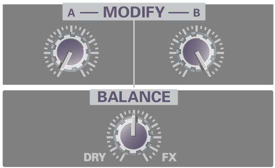
flowchart
graph TD
    A["A — MODIFY — B"] --> B["Balance"]
    B --> C["DRY"]
    B --> D["FX"]
7. ROBOT
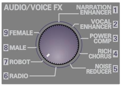
■ Default settings
These settings simulate a robotic, unpitched voice.

flowchart
graph TD
    A["A — MODIFY — B"] --> B["Balance"]
    B --> C["DRY"]
    B --> D["FX"]
■ Space invader
These settings produce the sound of an alien voice that might be heard in an SF movie.
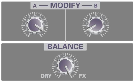
flowchart
graph TD
    A["A — MODIFY — B"] --> B["Balance"]
    B --> C["DRY"]
    B --> D["FX"]
■ Big robot
These settings produce the impression of a large robot.
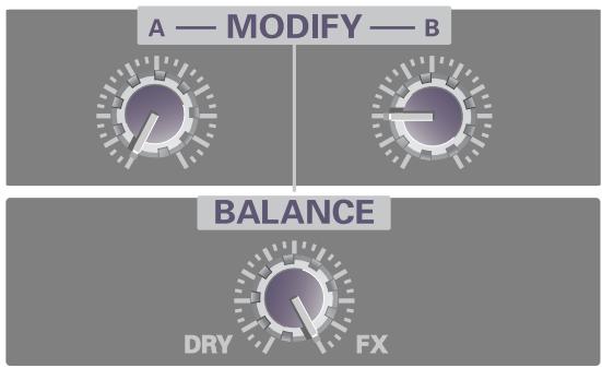
flowchart
graph TD
    A["A — MODIFY — B"] --> B["Balance"]
    B --> C["DRY"]
    B --> D["FX"]
8. MALE
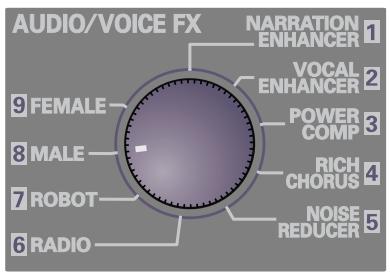
■ Default settings
These settings transform a female voice into a male voice.
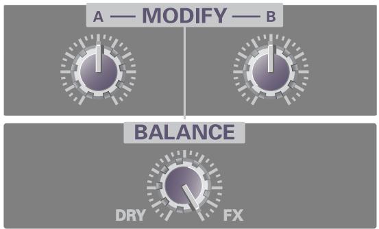
flowchart
graph TD
    A["A — MODIFY — B"] --> B["Balance"]
    B --> C["DRY"]
    B --> D["FX"]
■ Anonymous interview
These settings modify the voice in a way that makes it difficult to identify.
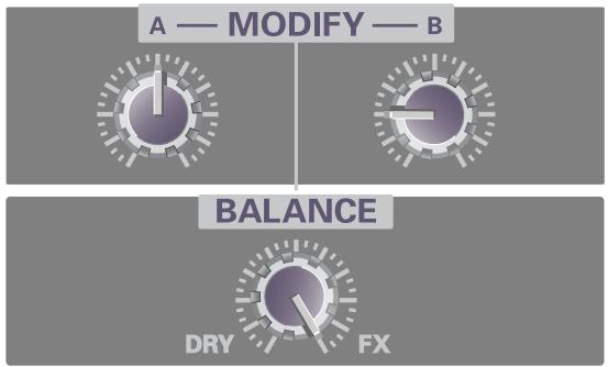
flowchart
graph TD
    A["A — MODIFY — B"] --> B1["Process Step 1"]
    A --> B2["Process Step 2"]
    B1 --> C1["DRY"]
    B2 --> C2["FX"]
■ Duet
These settings transform a solo into a duet.
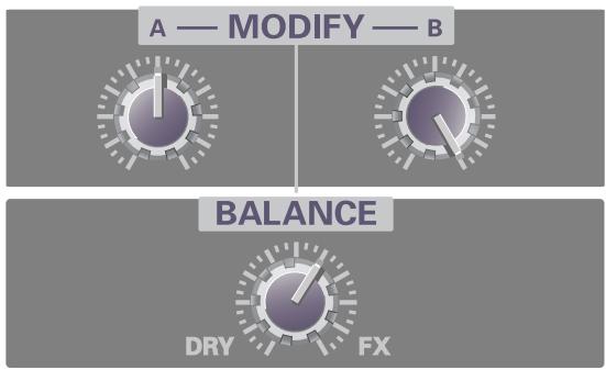
flowchart
graph TD
    A["A — MODIFY — B"] --> B["Balance"]
    B --> C["DRY"]
    B --> D["FX"]
9. FEMALE
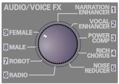
■ Default settings
These settings transform a male voice into a female voice.
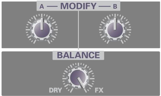
flowchart
graph TD
    A["MODIFY"] --> B["Balance"]
    B --> C["DRY FX"]
Child's voice
These settings produce a child-like voice.
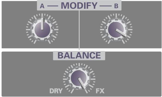
■ Duet
These settings transform a solo into a duet.
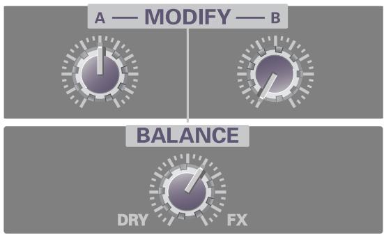
flowchart
graph TD
    A["A — MODIFY — B"] --> B["Balance"]
    B --> C["DRY"]
    B --> D["FX"]
MEMO
Supplementary information
Connecting the M-100FX to your computer
■ What is a driver?
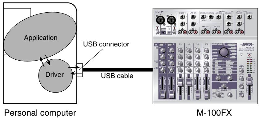
The “driver” is software that transfers data between your computer application and the M-100FX when your computer and the M-100FX are connected via a USB cable.
The driver passes data from your application software to the M-100FX, and from the M-100FX to your application.
The procedure for installation and settings will depend on your system.
Proceed to the page for the system you are using.
- Windows XP/2000 users....(p. 125)
- Windows Me users....(p. 126)
- Windows 98 users....(p. 128)
• Macintosh users....(p. 135)
Windows XP/2000 users
- With the M-100FX disconnected, start up Windows.
Disconnect all USB cables except for a USB keyboard and USB mouse (if used).
- Exit all currently running software (applications).
If you are using a virus checker or similar software, be sure to exit it as well.
- Place the M-100FX's ADVANCE (mode select) switch in the OFF position.
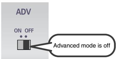
-
Use the USB cable to connect the M-100FX to your computer.
-
With the power switch turned OFF, connect the AC adaptor to the M-100FX.
- Connect the AC adaptor to an electrical outlet.
-
Use the USB cable to connect the M-100FX to your computer.
-
Lower the M-100FX's master fader to the minimum position, and turn ON the power switch.
The M-100FX will be detected automatically, and the driver will be installed.
- When installation is complete, restart Windows.
Next, you will need to make the driver settings.
(→Settings and checking (p. 131))

Once the connections have been completed, turn on power to your various devices in the order specified. By turning on devices in the wrong order, you risk causing malfunction and/or damage to speakers and other devices.

Always make sure to have the volume level turned down before switching on power. Even with the volume all the way down, you may still hear some sound when the power is switched on, but this is normal, and does not indicate a malfunction.

If you are using Windows XP, the installation has been completed when the message near the taskbar saying that “Found New Hardware” has disappeared.
Windows Me users
- With the M-100FX disconnected, start up Windows.
Disconnect all USB cables except for a USB keyboard and USB mouse (if used).
- Exit all currently running software (applications).
If you are using a virus checker or similar software, be sure to exit it as well.
- Place the M-100FX's ADVANCE (mode select) switch in the OFF position.

-
Use the USB cable to connect the M-100FX to your computer.
-
With the power switch turned OFF, connect the AC adaptor to the M-100FX.
- Connect the AC adaptor to an electrical outlet.
-
Use the USB cable to connect the M-100FX to your computer.
-
Set the M-100FX's power switch to the ON position.
- Windows will detect the M-100FX, and the "Add New Hardware Wizard" dialog box will appear.
Make sure that Automatic search for a better driver (Recommended) is selected, and click [Next].
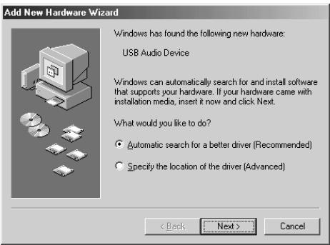
- Driver detection will begin.

Once the connections have been completed, turn on power to your various devices in the order specified. By turning on devices in the wrong order, you risk causing malfunction and/or damage to speakers and other devices.

Always make sure to have the volume level turned down before switching on power. Even with the volume all the way down, you may still hear some sound when the power is switched on, but this is normal, and does not indicate a malfunction.
8. When the driver has been found, driver installation will begin.
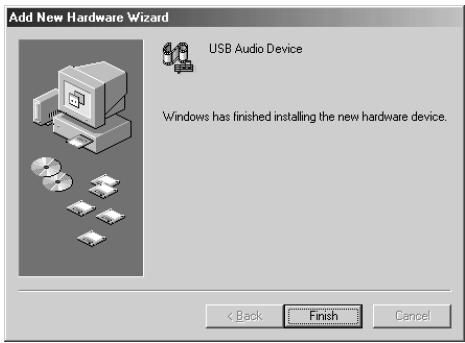
9. Once the driver has been installed, a dialog box will inform you of this. Click [Finish].
10. Restart Windows.
Next, you will need to make the driver settings.
(→Settings and checking (p. 131))

Depending on your system, a certain amount of time may be required for the device to be detected after the driver has been installed.
Windows 98 users
The USB composite device driver is installed first, then the USB audio device driver is installed. Use the following procedure to install the drivers.
- With the M-100FX disconnected, start up Windows.
Disconnect all USB cables except for a USB keyboard and USB mouse (if used).
- Exit all currently running software (applications).
If you are using a virus checker or similar software, be sure to exit it as well.
- Place the M-100FX's ADVANCE (mode select) switch in the OFF position.
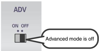
-
Use the USB cable to connect the M-100FX to your computer.
-
With the power switch turned OFF, connect the AC adaptor to the M-100FX.
- Connect the AC adaptor to an electrical outlet.
-
Use the USB cable to connect the M-100FX to your computer.
-
Set the M-100FX's power switch to the ON position.
- USB composite device will be detected automatically, and the "Add New Hardware Wizard" dialog box will appear.
Click [Next].


Once the connections have been completed, turn on power to your various devices in the order specified. By turning on devices in the wrong order, you risk causing malfunction and/or damage to speakers and other devices.

Always make sure to have the volume level turned down before switching on power. Even with the volume all the way down, you may still hear some sound when the power is switched on, but this is normal, and does not indicate a malfunction.

If this dialog box does not appear, refer to “Find new hardware wizard” does not execute automatically (p. 173).
- When “What do you want Windows to do?” appears, select “Search for the best driver for your device (Recommended)”, and click [Next].
![Add New Hardware Wizard What do you want Windows to do? • Search for the best driver for your device. [Recommended]. • Display a list of all the drivers in a specific location, so you can select the driver you want. < Back Next > Cancel](/content/2020/04/130961/images/f2f91c9cad8ff4f657678b6739499fea2120ea0dc7ff77f58b711173d72e7492.jpg)
- A dialog box like the one shown will appear. Check CD-ROM drive, and click [Next].
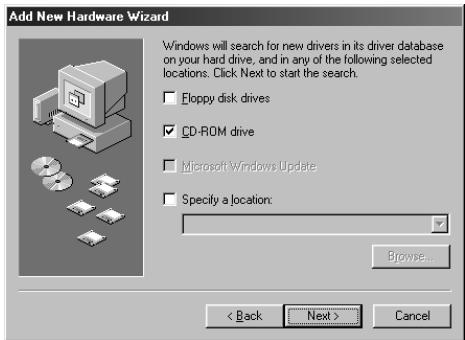
- A dialog box like the one shown will appear. Click [Next].
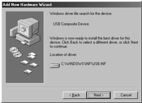
- File (driver) copying will begin.
If the Windows CD-ROM is not inserted in the CD-ROM drive, a “Insert Disk” dialog box may appear. In this case, insert the Windows CD-ROM into the CD-ROM drive and click [OK].
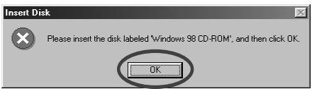
- When installation of the USB Composite Device driver is completed, a dialog box like the one shown here will appear.
Click [Finish].
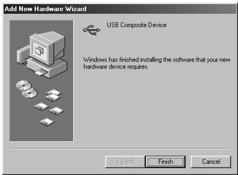
- Next, the USB audio device will be detected automatically, and the "Add New Hardware Wizard" dialog box will appear.
Click [Next], and proceed with the installation in the same way as in steps 8–11 (p. 129).
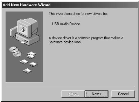
- When installation of the USB audio device driver is complete, a dialog box like the one shown here will appear.
Click [Finish].
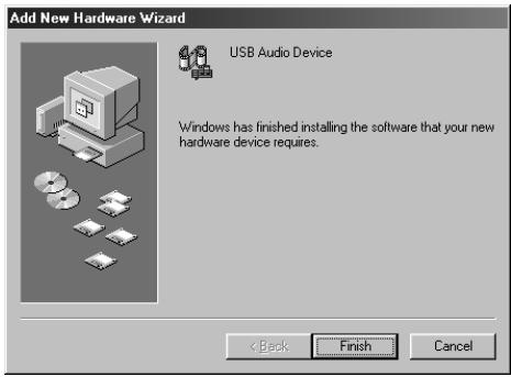
- Installation of the USB composite device driver and USB audio device driver has been completed.
Restart Windows.
Next, you will need to make the driver settings.
(→Settings and checking (p. 131))
Settings and checking
■ Specifying the audio input/output destination
Windows XP/2000/Me users
1. Open Control Panel.
Windows XP
Click the Windows Start button, and from the menu that appears, select Control Panel.
Windows 2000/Me
Click the Windows Start button, and from the menu that appears, select Settings | Control Panel.
2. Open the Sounds and Audio Devices Properties dialog box (or in Windows 2000/Me, Sounds and Multimedia Properties).
Windows XP
In “Pick a category”, click “Sound, Speech, and Audio Devices”. Next, in “or pick a Control Panel icon”, click the Sounds and Audio Devices icon.
Windows 2000/Me
In Control Panel, double-click the Sounds and Multimedia icon to open the “Sounds and Multimedia Properties” dialog box.
3. Click the Audio tab.
4. For MIDI music playback, click the t located at the right of [Default device] (or in Windows 2000/Me, [Preferred device]), and select the following from the list that appears.
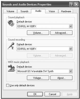
| Sound playback | Windows XP |
| EDIROL M-100FX | |
| Windows 2000/Me | |
| USB Audio Device | |
| Sound recording | Windows XP |
| EDIROL M-100FX | |
| Windows 2000/Me | |
| USB Audio Device |
5. Close the Sounds and Audio Devices Properties dialog box.
Click [OK] to complete the settings.
This completes driver settings.
Next, you will need to make the Volume Control setting.
(→Volume Control setting (p. 133))
MEMO
Depending on how your system is set up, the
Sounds and Audio
Devices icon may be displayed directly in the
Control Panel (the Classic view). In this case, double-click the Sounds and
Audio Devices icon.
MEMO
If the Sound and
Multimedia icon is not displayed, click “Show all control panel options” in the frame at the left.
MEMO
For MIDI music playback, you can leave these settings as they are.
Windows 98 users
1. Open Control Panel.
Click the Windows Start button, and from the menu that appears, select Settings | Control Panel.
2. Open the Multimedia Properties dialog box.
In Control Panel, double-click the Multimedia icon to open the “Multimedia Properties” dialog box.
3. Click the Audio tab.

4. In the playback and recording areas, click ▼ beside Preferred Device, and select the USB Audio Device from the list that appears.
5. Close the Multimedia Properties dialog box. Click [OK] to complete the settings.
This completes driver settings.
Next, you will need to make the Volume Control setting.
(→Volume Control setting (p. 133))
■ Volume Control setting
1. Open the Volume Control.
Click the Windows Start button, and choose Programs (in Windows XP, All Programs) | Accessories | Entertainment | Volume Control.
Example: Windows XP
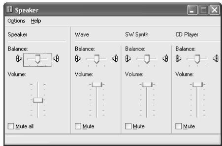
2. Raise or lower the slider to adjust the volume of the M-100FX.
The M-100FX can use the Windows volume control to adjust the output volume.
You will be able to use the M-100FX at the best audio quality if you set the Volume Control volume to the maximum setting.
Items that can be set
| CD Player(CD Audio) | Controls the volume of “audio CDs” on the internal CD-ROM drive of the computer. (*1) |
| WAVE | Controls the volume of sound output from the “EDIROL M-100FX” audio output device. Digital output and analog output will change. |
| Synthesizer(SW Synth) | Controls the volume of the software synthesizer built into Windows. |
*1:
If the CD playback volume does not change when you adjust this control, then change the WAVE volume.
If you are using Windows 2000 and the CD Player is not displayed, check “Enable digital music CDs for this CD playback device” in Digital CD Playback.
(→When playing audio CDs from the computer's internal CD-ROM drive, or using the M-100FX to play game music (p. 134))
MEMO
If the Volume Control is not installed on your computer, use the Control Panel icon Add or Remove Programs to install it. For details on installation, refer to the Windows manual or Help.
NOTE
If Mute is checked or if the slider is lowered all the way, no sound will be output from the M-100FX.
When playing audio CDs from the computer's internal CD-ROM drive, or using the M-100FX to play game music
Windows XP/2000 users:
- Open the System Properties dialog box.
Select Start | Settings | Control Panel, and in the Control Panel, double-click the System icon.
(Windows XP- Click the Windows Start button, and from the menu that appears, select Control Panel.) - Open the Device Manager.
Click the Hardware tab, and click the Device Manager button. - Open the CD-ROM drive's Properties.
In CD-ROM drive, double-click the CD-ROM drive that you are using. In Digital CD Playback, check the “Enable digital CD audio for this CD-ROM device” item.
Windows Me users:
- Open System Properties.
Select Start | Settings | Control Panel, and in Control Panel, double-click the System icon. - Open the CD-ROM drive's Properties.
Double-click the CD-ROM icon, and then double-click the CD-ROM drive that you are using. - Click the Properties tab, and in Digital CD Playback, check the “Enable digital CD audio for this CD-ROM device” item.
Windows 98 users:
- Open the Multimedia Properties dialog box.
Select Start | Settings | Control Panel, and in Control Panel, double-click the Multimedia icon. - Click the Music CD tab, and check the “Enable digital CD audio for this CD-ROM device” item.
* Depending on your system, playback may still not be possible. For details, please contact the manufacturer of your computer. If you are using a PC-card (PCMCIA) type CD-ROM drive, playing back WAVE data from a CD-ROM or playing an audio CD may cause interrupted sound, or possibly no sound at all.
Macintosh users
- With the M-100FX disconnected, start up Macintosh.
Disconnect all USB cables except for a USB keyboard and USB mouse (if used).
- Exit all currently running software (applications).
If you are using a virus checker or similar software, be sure to exit it as well.
- After starting up Mac OS, select Apple System Profiler from the Apple menu.
The “Apple System Profiler” dialog box will appear.
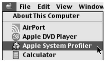
-
Click the Devices and Volumes tab.
-
Place the M-100FX's ADVANCE (mode select) switch in the OFF position.
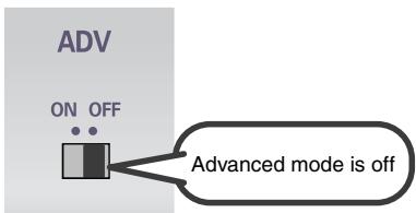
-
Use the USB cable to connect the M-100FX to your computer.
-
With the power switch turned OFF, connect the AC adaptor to the M-100FX.
- Connect the AC adaptor to an electrical outlet.
-
Use the USB cable to connect the M-100FX to your computer.
-
Set the M-100FX's power switch to the ON position.
- Wait for approximately five seconds.
The M-100FX will use the driver included with Mac OS.
While you are waiting, the screen display will not change, but the M-100FX is being detected. Do not touch the mouse or keyboard.

Once the connections have been completed, turn on power to your various devices in the order specified. By turning on devices in the wrong order, you risk causing malfunction and/or damage to speakers and other devices.

Always make sure to have the volume level turned down before switching on power. Even with the volume all the way down, you may still hear some sound when the power is switched on, but this is normal, and does not indicate a malfunction.
9.
In order to check that detection has been completed, once again go to “Apple System Profiler”, and select “Update all information” from the Commands menu.
In the USB area, three audio devices will be displayed.
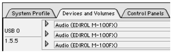
If these are displayed correctly, driver installation has succeeded.
10.
In the File menu, click Quit to close “Apple System Profiler”.
If they are not displayed correctly, disconnect the M-100FX, wait for about ten seconds, and then repeat the procedure from step 2.
Next, you will need to make the driver settings.
(→Settings the sound input/output (p. 137))
■ Settings the sound input/output
1. From the Apple menu, select Control Panel - Sound.
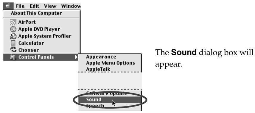
2. Click the Speakers tab or Speaker Settings.
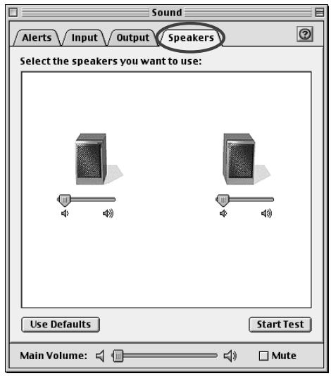
3. With the volume turned down on the M-100FX and on your peripheral audio equipment, click [Start Test].
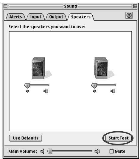
Test signals will be output from the M-100FX; left first, then right, as indicated in the screen.
![ROLAND M-100FX - With the volume turned down on the M-100FX and on your peripheral audio equipment, click [Start Test]. - 2](/content/2020/04/130961/images/1faf20a01f094bd9e3a528c904ad3e372a2646698dcd6c4a2a9cef91b5fe9d7c.jpg)
The main volume slider will not move.
- In the Sound dialog box, click the Input tab. In Choose a source for sound input (Device), select USB audio.
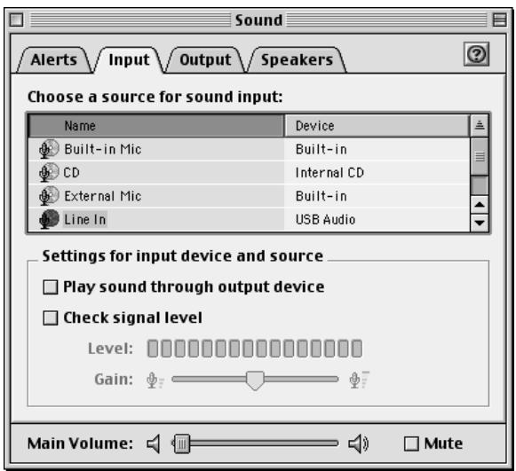
- When you are finished making settings, close the Sound dialog box. From the File menu, select Quit.
This completes driver settings.
![ROLAND M-100FX - With the volume turned down on the M-100FX and on your peripheral audio equipment, click [Start Test]. - 4](/content/2020/04/130961/images/d4661a8b8899be96a816f4514561b30a40f3e210f0df4a20e17cc6e311d72b95.jpg)
Do not check “Play sound through output device”.
Connecting the M-100FX to your computer
Windows XP/2000-Anwender
(→Volume Control setting (S. 133))
MEMO
Connecting the M-100FX to your computer
Windows XP/2000
| Lecture audio | Windows XP |
| EDIROL M-100FX | |
| Windows 2000/Me | |
| Périphérique audio USB | |
| Enregistrement audio | Windows XP |
| EDIROL M-100FX | |
| Windows 2000/Me | |
| Périphérique audio USB |
(→Volume Control setting (p. 133))
MEMO
Connecting the M-100FX to your computer
2. Fare clic sulla scheda Speakers o Speaker Settings.
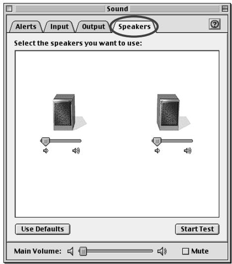
Connecting the M-100FX to your computer
If you want to use the M-100FX with ASIO-compatible software or an application that supports 24-bit audio, you must use Advance mode. This requires that you install a special driver.
- ASIO (Steinberg Audio Stream In/Out Interface) This is an audio interface protocol promoted by the Steinberg Corporation. If the M-100FX is used with ASIO-compatible software, the audio synchronization will be more accurate, allowing you to utilize a more sophisticated music production environment.
Advanced mode
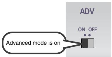
In this position, Advanced mode is on.

In order for the setting of the ADV (Advanced mode select) switch to take effect, you must exit all sequence software or other applications that are using the M-100FX, and turn the power of the M-100FX off, then on again.
The special driver included on the CD-ROM lets you record/play/edit audio at higher quality and more stable timing. In Advanced mode, the M-100FX is able to exchange audio data with your computer at a 24-bit depth and 44.1 kHz sampling frequency. Use Advanced mode if you are using the M-100FX with high-quality audio recording/playback/editing software such as applications that support 24-bit audio such as the Cakewalk series and Cool Edit, or ASIO-compatible applications such as Cubase VST, Logic Audio, or Singer Songwriter.
The procedure for installation and settings will depend on your system.
Proceed to the page for the system you are using.
- Windows XP users......(p. 163)
- Windows 2000 users......(p. 164)
- Windows Me/98 users......(p. 165)
• Macintosh users .....(p. 168)
Installing the special driver (Windows)
■ Windows XP users
- With the M-100FX disconnected, start up Windows. Disconnect all USB cables except for a USB keyboard and USB mouse (if used).
* If you are using Windows XP Professional, you must log on using a user name with an administrative account type (e.g., Administrator).
- Click the Windows Start button, and from the menu that appears, select Control Panel. In Control Panel, double-click the System icon.
* If you are using Windows XP and cannot find System, click "Switch to classic view" to select the Classic view.
-
Click the Hardware tab, and then click [Driver Signing].
-
In the Driver Signing Options dialog box, select "Ignore" and click [OK].
* If the current setting is "Warn" or "Block", set it to "Ignore" here, then change it back to the original setting after you have finished installing the driver.
-
Click [OK] to close the System Properties dialog box.
-
Exit all currently running software (applications). Also close any open windows. If you are using virus checking or similar software, be sure to exit it as well.
-
Insert the CD-ROM into the CD-ROM drive of your computer.
-
Click the Windows Start button. From the menu that appears, select "Run...".
-
In the "Run..." dialog box, input the following into the "Open" field, and click [OK]. D:\DRIVER\USB_XP2K\SETUPINF.EXE
* The drive name “D:” may be different for your system. Specify the drive name of your CD-ROM drive.
-
The SetupInf dialog box will appear. You are now ready to install the driver.
-
Place the M-100FX's ADVANCE (mode select) switch in the ON position.
-
With the power switch turned OFF, connect the AC adaptor to the M-100FX.
-
Connect the AC adaptor to an electrical outlet.
-
Use the USB cable to connect the M-100FX to your computer.
-
Set the M-100FX's power switch to the ON position.
-
The Found New Hardware Wizard will appear. Make sure that the screen indicates "EDIROL M-100FX", select "Install from a list or specific location (Advanced)", and click [Next].
- Select "Don't search. I will choose the driver to install," and click [Next].
- Make sure that the “Model” field indicates “EDIROL M-100FX”, and click [Next].
* If the "Driver Signing Options" setting is not set to "Ignore" in step 4, the Install Hardware dialog box will appear. If the [Continue Anyway] button is displayed, click [Continue Anyway] to continue the installation. If you are unable to continue, click [STOP Installation] or [OK], and try the driver installation once again from step 1.
- The Insert Disk dialog box will appear. Click [OK].
- The Files Needed dialog box will appear. Input the following into the “Copy files from” field, and click [OK].
D:\DRIVER\USB_XP2K
* If the "Driver Signing Options" setting is not set to "Ignore" in step 4, the Install Hardware dialog box will appear. Click [Continue Anyway] to continue the installation.
- The Found New Hardware Wizard will appear. Verify that “EDIROL M-100FX” is displayed, and click [Finish]. Wait until “Found New Hardware” appears near the taskbar.
- When driver installation has been completed, the System Settings Change dialog box will appear. Click [Yes].
Windows will restart automatically.
Next, you will need to make the driver settings.
(→ Driver settings (p. 166))
■ Windows 2000 users
- With the M-100FX disconnected, start up Windows. Disconnect all USB cables except for a USB keyboard and USB mouse (if used).
* You must log on using a user name with an administrative account type (e.g., Administrator). - Click the Windows Start button, and from the menu that appears, select Settings | Control Panel. In Control Panel, double-click the System icon.
- Click the Hardware tab, and then click [Driver Signature].
- In the Driver Signing Options dialog box, select "Ignore" and click [OK].
* If the current setting is "Warn" or "Block", set it to "Ignore" here, then change it back to the original setting after you have finished installing the driver.
- Click [OK] to close the System Properties dialog box.
- Exit all currently running software (applications). Also close any open windows. If you are using virus checking or similar software, be sure to exit it as well.
- Insert the CD-ROM into the CD-ROM drive of your computer.
- Click the Windows Start button. From the menu that appears, select "Run...".
- In the “Run...” dialog box, input the following into the “Open” field, and click [OK].
D:\DRIVER\USB\_XP2K\SETUPINF.EXE
* The drive name “D:” may be different for your system. Specify the drive name of your CD-ROM drive.
-
The SetupInf dialog box will appear. You are now ready to install the driver.
-
Place the M-100FX's ADVANCE (mode select) switch in the ON position.
- With the power switch turned OFF, connect the AC adaptor to the M-100FX.
- Connect the AC adaptor to an electrical outlet.
- Use the USB cable to connect the M-100FX to your computer.
- Set the M-100FX's power switch to the ON position.
* If the "Driver Signing Options" setting was not set to "Ignore" in step 4, a dialog box will inform you that the digital signature was not found. If the [Yes] button is displayed, click [Yes] to continue installation. If you are unable to continue, click [No] or [OK], and try the driver installation once again from step 1.
- The Insert Disk dialog box will appear. Click [OK].
- The Files Needed dialog box will appear. Input the following into the "Copy files from" field, and click [OK].
D:\DRIVER\USB\_XP2K
* If the "Driver Signing Options" setting was not set to "Ignore" in step 4, a dialog box will inform you that the digital signature was not found. Click [Yes] to continue installation.
- The Found New Hardware Wizard will appear. Verify that “EDIROL M-100FX” is displayed, and click [Finish].
- When driver installation has been completed, the System Settings Change dialog box will appear. Click [Yes].
Windows will restart automatically.
Next, you will need to make the driver settings.
(→ Driver settings (p. 166))
■ Windows Me/98 users
- With the M-100FX disconnected, start up Windows. Disconnect all USB cables except for a USB keyboard and USB mouse (if used).
- Exit all currently running software (applications). Also close any open windows. If you are using virus checking or similar software, be sure to exit it as well.
- Insert the CD-ROM into the CD-ROM drive of your computer.
- Click the Windows Start button. From the menu that appears, select "Run...".
- In the "Run..." dialog box, input the following into the "Open" field, and click [OK]. D:\DRIVER\USB_ME98\SETUPINF.EXE
* The drive name “D:” may be different for your system. Specify the drive name of your CD-ROM drive.
- The SetupInf dialog box will appear.
You are now ready to install the driver.
* If a message recommends that you restart Windows, restart Windows as directed, and then proceed to the next step. - Place the M-100FX's ADVANCE (mode select) switch in the ON position.
- With the power switch turned OFF, connect the AC adaptor to the M-100FX.
-
Connect the AC adaptor to an electrical outlet.
-
Use the USB cable to connect the M-100FX to your computer.
- Set the M-100FX's power switch to the ON position.
- The driver will be installed automatically.
- In the SetupInf dialog box, click [OK].
* If a message recommends that you restart Windows, restart Windows as directed.
Next, you will need to make the driver settings.
(→ Driver settings (p. 166))
Driver settings
Windows XP/2000/Me
Set the Default Device for Sound Recording and Playback (in Windows 2000/Me, [Default Device]) as follows.
| Sound recording | EDIROL M-100FX Out |
| Sound playback | EDIROL M-100FX In |
→ For details on how to make this setting, refer to Specifying the audio input/output destination (p. 131).
Windows 98
Set the [Default Device] for playback and recording as follows.
| Playback | EDIROL M-100FX Out |
| Recording | EDIROL M-100FX In |
→ For details on how to make this setting, refer to Specifying the audio input/output destination (p. 131).
■ About the input/output devices
| Output devices |
| EDIROL M-100FX OutThis sends audio data from the computer to the M-100FX. This is the setting you will normally use, such as when using the M-100FX with Media Player. You will also select this setting when using an application such as SONAR in WDM driver mode, or when using a Direct Sound application. |
| MME Out EDIROL M-100FXThis sends audio data from the computer to the M-100FX. Use this setting if you are using the M-100FX with an application that does not have a WDM driver mode, or if you want to use 24-bit audio with an application does not support ASIO (such as Cool Edit).* Windows XP/2000 only |
| Input devices |
| EDIROL M-100FX InThis receives audio data sent by the M-100FX to the computer. This is the setting you will normally use, such as when using the M-100FX with Media Player. You will also select this setting when using an application such as SONAR in WDM driver mode. |
| MME In EDIROL M-100FXThis receives audio data sent by the M-100FX to the computer. Use this setting if you want to use 24-bit audio with an application that does not have a WDM driver mode or does not support ASIO (such as Cool Edit).* Windows XP/2000 only |
| ASIO device |
| If you are using the M-100FX with an ASIO-compatible application such as Cubase, select “EDIROL M-100FX” as the ASIO setting on your application.* To prevent an audio oscillation loop or double monitoring, turn monitoring Off in your application, or use ASIO Direct Monitor. |

ASIO Direct Monitor
Sine the M-100FX's INPUT is always monitored, the M-100FX does not support ASIO Direct Monitor. Support is simulated in order to improve usability.
■ Adjusting the audio latency
When using the M-100FX in Advanced mode, you can change the driver settings to adjust the latency of the audio. To adjust the latency, change the Buffer Size in the driver settings dialog box.
- As described in Opening the special driver settings dialog box (p. 167), open the "Driver Settings" dialog box.
- Adjust the driver buffer size.
The following setting will produce the shortest latency.
Windows:
Set "Audio Buffer Size" to the far left (Min).
Macintosh:
Set "Buffer Size" to the far left (Min).
- Click [OK] to close the driver settings dialog box.
- Restart the application that is using the M-100FX.
If you are using an application that has a function for testing audio devices, get it to perform its tests.
- Play back audio data on your application.
If interruptions occur in the sound, repeat this procedure, and gradually increase the buffer size specified in step 2 until interruptions no longer occur.
* Depending on the application you are using, there may be a buffer size or latency adjustment function among the audio settings of the application as well. For details, refer to the operation manual for your application.
Opening the special driver settings dialog box
If using Windows:
- Open the "Control Panel" and double-click "EDIROL M-100FX".
- The “EDIROL M-100FX Driver Settings” dialog box will appear.
* In Windows XP, click “Switch to classic view” to switch the display to the classic view. EDIROL M-100FX will not be displayed unless the classic view is selected.
* In Windows Me, click "View all Control Panel options".
If using Macintosh:
Open the ASIO Control Panel from the Audio Settings dialog box of your ASIO-compatible application. The name of the Audio Settings dialog box and the procedure for opening the ASIO Control Panel will differ depending on your application. For details, refer to the operation manual for your application.
Installing the special driver (Macintosh)

This driver cannot be used in Mac OS X. If you are using a Macintosh in which Mac OS X is installed, you must start up using Mac OS 9, install the driver, and use it in Mac OS 9. You cannot use this driver in the Classic environment.
■ Installing the audio driver
- With the M-100FX disconnected, start up Macintosh. Disconnect all USB cables except for a USB keyboard and USB mouse (if used).
- Exit all currently running software (applications). Also close any open windows. If you are using virus checking or similar software, be sure to exit it as well.
- Insert the CD-ROM into the CD-ROM drive of your Macintosh.
- Double-click the M-100FX Driver-E Installer icon (found in the Driver E (Mac OS 9) folder of the CD-ROM).
- Verify the installation location, and click [Install]. The location for installation will depend on your system. Make sure that the startup disk for the system you are currently using is selected.
- If a message like "This installation requires your computer to restart after installing this software —". is displayed, click [Continue].
The other currently running applications will exit, and installation will continue.
- A dialog box will indicate Installation completed. Click [Restart] to restart your Macintosh.
- Place the M-100FX's ADVANCE (mode select) switch in the ON position.
- With the power switch turned OFF, connect the AC adaptor to the M-100FX.
- Connect the AC adaptor to an electrical outlet.
- Use the USB cable to connect the M-100FX to your computer.
- Set the M-100FX's power switch to the ON position.
■ Installing the ASIO driver
The M-100FX supports ASIO 1.0 24-bit audio.
The ASIO driver of the M-100FX supports the following audio input/output channels.
• Audio input .....24/16 bit 1 stereo ch. (2 monaural chs.)
• Audio output.....24/16 bit 1 stereo ch. (2 monaural chs.)

In Advanced mode, the M-100FX cannot play back audio data from the Macintosh's sound manager (such as audio CDs and alert sounds).
This section explains how to install the ASIO driver that allows the M-100FX to be used by your sequencer software or audio editing software.
- From the Driver E (Mac OS 9) - ASIO folder of the CD-ROM, copy M-100FX ASIO1.0 24bit to the ASIO Drivers folder within the folder of the ASIO-compatible software you are using (e.g., Cubase VST, Logic Audio, Digital Performer, Metro, or SPARK LE).
- Start up your ASIO-compatible software (e.g., Cubase VST, Logic Audio, Digital Performer, Metro, or SPARK LE).
- Open the Audio setting dialog box of your ASIO-compatible software, and select M-100FX ASIO1.0 24bit as the ASIO Device.
The Audio setting dialog box will be named differently depending on your software. For details refer to the manual of your software.

An M-100FX ASIO 1.0 16-bit driver is also included. If you are using software that does not support 24-bit audio, use M-100FX ASIO 1.0 16-bit.
Settings for your software
If your software is set to monitor audio data during recording, the audio data will loop, and will not be recorded correctly. Monitoring of audio data during recording must be turned off. For details on this setting, refer to the manual of the software you are using.
■ Settings for Cubase VST users
The explanation in this manual is based on the English version of Cubase VST 5.0. Please be aware that some menu items may be named differently in other versions of the software.
- In Cubase VST, execute Options - AudioSetup - System....
- As the ASIO Device, select M-100FX ASIO 24bit.
- For the Monitoring setting, select Global Disable.
- Click [OK] to close the dialog box.
■ Settings for Logic users
- In Logic, choose Audio - Audio Hardware & Drivers....
- In the “Preferences” dialog box, open the “ASIO” item.
- Make sure that "Software Monitoring" is unchecked.

Roland cannot guarantee operation of or provide support regarding sequencer software and audio editing software produced by another manufacturer. Please contact the manufacturer of the software you are using.
If you experience problems, read this chapter first. It contains tips for solving most problems.
Problems with the M-100FX
Sound contains crackles or distortion
• Could the input volume be excessive?
If the input volume (level) is excessive, the sound may be distorted. If you are inputting audio from the input jacks, adjust the input volume (level) of the M-100FX.
- Are you mixing multiple channels?
Even if the input volume (level) of one channel is appropriate, mixing two or more channels together may make the sound loud enough to produce distortion. Re-adjust the input level of each channel.
- Are the EQ levels appropriate?
If the equalizer knobs (HI/LO) are turned too far toward the right (+15 dB), the sound may distort. Use the equalizer knobs (HI/LO) to re-adjust the EQ levels of each channel.
- Is there a problem with the level indication shown by the master volume indicator?
If the sound is distorted even though there is no problem with the indication of the master volume indicator, the output volume is appropriate, but the input volume is excessive. Please adjust the input volume (level) of the M-100FX.
Noise is heard in the sound
- Are you applying the audio/voice effect MALE or FEMALE?
The mic is picking up unwanted sound from the background. Make the necessary changes in your location so that unwanted sound is not present while you speak into the mic.
Loud whining, howling, or squealing sounds are produced
• Is a mic connected?
Howling could be produced depending on the location of microphones relative to speakers. This can be remedied by:
- Changing the orientation of the microphone(s).
- Relocating microphone(s) at a greater distance from speakers.
- Lowering volume levels.
- Are audio devices connected to the M-100FX?
If the inputs and outputs of your audio device are both connected to the M-100FX, the signal may create a loop. Check your connections.
Hum noise is heard even when the volume is low
• Is another device connected?
This is hum noise. This type of noise may be produced because the M-100FX and connected device are picking up electromagnetic waves. This type of noise can also be produced by the AC power supply frequency (50/60 Hz) or a large motor. Try moving motorized devices farther away from the M-100FX, or connect the M-100FX to a different AC outlet. You can also try connecting your device to a different input jack.
Reverb effect is not applied
• Could the reverb send level be too low?
The reverb send level may be too low for you to hear the effect. Turn the reverb/AUX send level knob toward the right to increase the level.
• Could the reverb type select knob be set to OFF?
There will be no effect if the reverb type select knob is set to OFF. Turn the reverb type select knob to a position other than OFF.
Soft voices or sounds disappear
• Could you be applying audio/voice effect 5. NOISE REDUCER?
If a mic is connected to mic input jacks 1 or 2 and the audio/voice effect NOISE REDUCER is applied, sound that is softer than a certain level may disappear. In this case, adjust the input level knob (GAIN) to raise the input level, or turn effect knob B toward the left.
If a device is connected to mic input jacks 1/2 to input sound, try increasing the volume of the connected device.
Can't hear the audio/voice effect
- Could the effect balance knob be set to the DRY (left) position?
There will be no effect if the knob is set to the DRY position. If you want a stronger effect, turn the knob toward FX (right).
ROBOT/MALE/FEMALE audio/voice effect is not satisfactory, or is unstable
These effects are applied by detecting the frequency of the input audio. The effect will not be satisfactory if the input audio level is too low, or if there is a large amount of background noise, or if more than one person is speaking. Input the voice of one person at an appropriate level.
Too much (or too little) reverb
To adjust the reverb depth, use the reverb/AUX send level knob of each channel to adjust the amount of signal that is sent to the reverb.
The volume level of the device connected to the mic input jacks, line input jacks, or external input jacks is too low.
• Could you be using a connection cable that contains a resistor?
Use a connection cable that does not contain a resistor.
• Is the device connected to the mic input jack?
Turn the input level knob toward the right to adjust the input level.
Can't hear sound from a mic connected to mic output jacks 1/2 (channels 1/2)
• Could you have connected a condenser mic that requires phantom power?
Lower the input level fader to the minimum position, and then turn the phantom power switch ON.
• Could a plug-in powered mic be connected?
The input from the plug-in powered mic jack takes priority. Input from a mic connected to the XLR/phone jack of mic input 1 will be ignored.
Input sound is all the way to left or right
• Could the pan/balance knob be set all the way to left or right?
Set the pan/balance knob to the center position.
Can't hear sound that is input to the RCA phono jacks of line inputs 3/4
- Could a phone plug be connected to line input jacks 3/4–5/6?
Both phone jacks and RCA phono jacks are provided for these inputs. If something is connected to both types of jacks, only the sound from the phone jacks will be input; the sound from the RCA phono jacks will be ignored.
The L and R channels are independent, so if a phone plug is connected to L and an RCA phono plug is connected to R, you will hear the audio from the phone plug input for the L channel, and the audio from the RCA phono plug input for the R channel.
Knobs and sliders of channels 1/2 feel different than those of channels 3/4–9/10
This is not a malfunction.
Problems related to the special driver

Problems common to Windows and Macintosh

Problems occurring only in Windows

Cannot install the driver correctly
- Is the CD-ROM correctly inserted into your CD-ROM drive?
Installation is not possible unless the CD-ROM included with the M-100FX is inserted in your CD-ROM drive. Make sure that the CD-ROM is correctly inserted into your CD-ROM drive.
- Is the CD-ROM or the lens of the CD-ROM dirty?
If the CD-ROM or the lens of the CD-ROM drive is dirty, the installer may not work correctly. Clean the disc and/or lens using a commercially-available CD cleaner or lens cleaner.
- Are you installing the software from a networked CD-ROM drive?
The software cannot be installed from a networked CD-ROM drive.
• Is there sufficient free space on your hard disk?
Delete unneeded files to increase the amount of free space. After deleting the unneeded files, empty the recycling bin.
• Is the power of the M-100FX turned on?
Make sure that the power switch of the M-100FX is set to the ON position.

• Is the M-100FX connected correctly?
Make sure that the USB connector of your computer is connected to the M-100FX by a USB cable. Check this, and if you are using Windows, close the Sounds and Audio Devices Properties dialog box (Sounds and Multimedia Properties in Windows 2000/Me, and Multimedia Properties in Windows 98), re-open the same dialog box once again, and specify the audio input/output destinations.
(→Specifying the audio input/output destination (p. 131))

"Find new hardware wizard" does not execute automatically

The “Insert Disk” dialog box does not appear

"Find new hardware wizard" ends before the process is completed
It may take about 15 seconds (or more) after the USB cable is connected for the M-100FX to be detected.
It has been found that in some cases, not all of the Windows 98 files required to support audio via USB are installed when a computer is shipped. Please contact the manufacturer of your computer.
• Is the USB cable connected correctly?
Make sure that the M-100FX and your computer are correctly connected via a USB cable.
• Is USB enabled on your computer?
Refer to the operation manual for your computer, and make sure that USB is enabled.
- Does your computer meet the USB specifications?
If you are using a computer that does not fulfill the electrical requirements of the USB specifications, operation may be unstable. In this case, you may be able to solve the problem by connecting a USB hub.
If the above actions do not solve the problem, it is possible that the M-100FX has been incorrectly detected by the computer. Re-install the driver.
(→Installing the special driver (Windows) (p. 163))

"Found unknown device" appears even though you installed the driver
- If your computer or USB hub has two or more USB connectors, and you connect the M-100FX to a USB connector to which the M-100FX has never been connected before, the “Unknown device” dialog box may appear even on a computer onto which you have already installed the driver.
Refer to Installing the special driver (Windows) (p. 163), and install the driver once again. This is not a malfunction.
If the “Found unknown device” dialog box appears even though the M-100FX is connected to the same USB connector as before, it is possible that the computer has detected the M-100FX incorrectly. Re-install the driver.
(→Installing the special driver (Windows) (p. 163))

An “Unknown driver found” dialog box appears, and you are unable to install the driver

Device Manager shows “?”, “!”, or “USB Composite Device”

Driver is not installed correctly
It is possible that the computer has detected the M-100FX incorrectly.
Re-install the driver.
(→Installing the special driver (Windows) (p. 163))
* If the problem still occurs after you have taken the above measures, please refer also to the Readme file for the USB driver. The Readme file is on the CD-ROM.

Can't install/delete/use the driver in Windows XP/2000
- Did you log on to Windows as a user with administrative privileges?
In order to install/delete/re-install the driver in Windows XP/2000, you must be logged into Windows as a user with administrative privileges, such as Administrator. For details, please contact the system administrator for your computer system.
- Did you make "Driver Signing Options"?
In order to install/re-install the driver, you must make “Driver Signing Options”.
(→Installing the special driver (Windows) (p. 163))
Deleting the special driver
■ Windows users
Here's how to uninstall the dedicated driver.
- Start up Windows with the M-100FX disconnected.
Disconnect all USB cables other than a USB keyboard or USB mouse.
* If you are using Windows XP Professional/2000, log on as a user that has administrative privileges (e.g., Administrator).
- Insert the CD-ROM into the CD-ROM drive of your computer.
- From the Windows Start menu, choose "Run...".
In the Run dialog box, input the following into the Open field, and click [OK].
Windows XP/2000 users:
D:\DRIVER\USB_XP2K\Uninstal.EXE
Windows Me/98 users:
D:\DRIVER\USB_ME98\Uninstal.EXE
* The drive name D: may be different on your system. Use the drive name for your CD-ROM drive.
- Follow the on-screen instructions to uninstall the driver.
■ Macintosh users
- Turn off the power of the M-100FX.
Also disconnect the USB cable (by which the M-100FX is connected) from your Macintosh. - From the system extensions folder, drag "USB M-100FX Driver" into the trash to delete it.
- Drag the ASIO driver you installed in Installing the ASIO driver (p. 168) into the Recycle Bin to delete it.
- Restart the Macintosh.
M-100FX:10-channel Mixer and Audio/Voice Effects
MIXER PART
■ Input
Connectors
Channel 1:
XLR type (phantom power), 1/4 inch TRS phone type (balanced / unbalanced)
Miniature phone type (plug-in powered mic)
Channel 2:
XLR Type (phantom power), 1/4 inch TRS phone type (balanced / unbalanced)
Channel 3/4, 5/6:
1/4 inch phone type, RCA phono type
Channel 7/8, 9/10:
RCA phono type
Frequency Response:
20 Hz to 20 kHz (0 dB/-2 dB)
Nominal Input Level
Channel 1, 2: -60 to +6 dBu (variable)
Channel 3/4 to 9/10: +4 dBu
Input Impedance
Channel 1, 2: 50 k ohms
Channel 3/4 to 9/10: 50 k ohms
Equalizer
HI: +/- 15dB (10 kHz shelving type)
LO: +/- 15dB (100 kHz shelving type)
Control:
GAIN knobs (Channel 1, 2)
Equalizer HI knobs
Equalizer LO knobs
Reverb/AUX send level knobs (Channel 1, 2, 3/4 to 9/10)
Pan/balance knobs (Channel 1, 2, 3/4 to 9/10)
Input level faders (Channel 1, 2, 3/4 to 9/10)
Output
Connectors
Master output jacks, Monitor output jacks
1/4 inch phone type (L, R), RCA phono type (L, R)
Nominal Output Level: 0 dBu
Output Impedance: 1 k ohms
Residual Noise Level: -84 dBu (input terminated with 150 ohms, IHF-A, CH1/2 GAIN = -10 dB)
Headphones jack
Stereo 1/4 inch phone type
Nominal Output Level: +12 dBu
Output Impedance: 200 ohms
■ External Input/Output
Connectors
AUX Send
1/4 inch phone type
Nominal Output Level: 0 dBu
Output Impedance: 1 k ohms
STEREO AUX RETURN
1/4 inch phone type (L/MONO, R)
Nominal Input Level: -10 dBu
Input Impedance: 33 k ohms
■ Digital Output
Connectors
Digital output jacks
Optical type, Coaxial type (conform to S/P DIF)
■ Other connectors
USB connector
EFFECT PART
Audio/Voice Effect (for Channel 1, 2)
Types: 9
Audio/Voice effect knob, Effect adjustment knobs
Reverb Unit
Types: 10
Reverb type select knob, Reverb time adjustment knob
Signal Processing
Bit Depth
AD/DA conversion: 24 bits
PC interface: 24 bits (Advance Mode: ON)
16 bits (Advance Mode: OFF)
Sample Rate
Digital output: 44.1 kHz
AD/DA conversion: 44.1 kHz
Others
Power Supply
DC 9 V (AC adaptor)
Current Draw
800 mA
Dimensions
287 (W) × 269.4 (D) × 72.3 (H) mm
11-5/16 (W) x 10-5/8 (D) x 2-7/8 (H) inches
Weight
2.1 kg / 4 lbs 11 oz
Accessories
USB Cable
AC adaptor
Owner's manual
CD-ROM
* In the interest of product improvement, the specifications and/or appearance of this unit are subject to change without prior notice.
Numerics
24-bit 163, 168
A
AC adaptor 10
AC adaptor jack 17
ADV (Advanced mode select) switch 163
ADVANCE switch ..... 17, 125–126, 128, 135, 163–165
ADVANCE, interruttore .... 151, 153
Advanced mode 163, 167
ADVANCE-Schalter 139, 141
ASIO 124, 163
ASIO device 166
ASIO Direct Monitor 166–167
ASIO driver 168
Asymétrique 56
Audio/voice effect 14, 170–171
Audio/voice effect knob 15, 108–109, 111
AUDIO/VOICE FX 15
Auriculares 86
AUX input level knob 16, 110
AUX RETURN 13,110
AUX SEND 13
B
BALANCE 15
Balanced 12, 21
Base 88
BASS 32, 34, 48, 50, 64, 66, 80, 82
BASS (Bajos) 96, 98
Bilanciato 72
Block diagram 18
Condenser mic 12, 20–21
DEPTH 32, 34, 48, 50, 64, 66, 80, 82
DEPTH (Profundidad) 96, 98
Digital output jack 17, 106
Digital reverb 103
Effect adjustment knob 15
Effect balance knob .... 15, 112–113, 171
Effect knob 112-113
Effect switch 14, 108, 111
FORMANT ... 32, 36–37, 48, 52–53, 64, 68–69, 80, 84–85
FORMANT (Formantes) 96, 100–101
FORMANT (Modulador) 96
Formanten 52
Formantes 100
Formanti 84
Formants 36, 68
Frecuencia 97
Freddo 72
FREQUENCY .... 32–33, 48–49, 64–65, 80–81
Frequency 33,65
GAIN 12, 22, 41, 57, 73, 89, 106, 171
Gain 22, 57, 111
Ganancia 89
Ground 21,56
Ground terminal 18
Guadagno 73
H
HALL 103
Headphone jack 13
Headphone volume knob 16, 22, 106
Headphones 19
Heiß 40
HI 14,107,170
Hot 21,56
Hum 35,67,171
HUM CUT ...... 32, 35, 48, 51, 64, 67, 80, 83
Master Volume Fader 41
Master volume fader 16, 22, 106
Master volume indicator 16, 170
Mic 20
Mic input jack 12, 20, 110–111
Monitor volume knob 16, 22, 106
Monitores 86
NARRATION ENHANCER ...... 32–33, 48–49, 64–65, 80–81, 108–109, 113
PITCH ...... 32, 36–37, 48, 52–53, 64, 68–69, 80, 84–85
PITCH (Tono) 96, 100–101
PLATE 103
Plug-in powered input 12
Plug-in powered mic 21
Plugin-Mikrofon 40
POWER COMP 115
POWER COMPRESSOR ..... 32, 34, 48, 50, 64, 66, 80, 82
POWER COMPRESSOR (Compresor
de potencia) 96, 98
Power indicator 16
Power switch 17
Reverb send level 171
Reverb time 104
Reverb time adjustment knob 15
Reverb time knob 102–103
Reverb type select knob .... 15, 102–103, 110, 171
Reverb types 103
Reverb/AUX send level knob 14, 102–103, 108, 110, 171
RICH CHORUS 32, 34, 48, 50, 64, 66, 80, 82, 96, 98, 116
ROBOT .... 32, 36, 48, 52, 64, 68, 80, 84, 119
ROBOT (Robot) 96,100
Ronzio 83
ROOM 103
S
Sbilanciato 72
Security Slot 18
Sibilant 33
Sibilant (sibilante) 81
Sifflement 65
Silbido 97
Sin balance 88
SPRING 103
Stereo Control 14,111
Symétrique 56
Symmetrisch 40
T
Tierra 88
TONE 32-33, 48-49, 64-65, 80-81
TONE (Tono) 96–97
TUNING 32, 35, 48, 51, 64, 67, 80, 83
VOCAL ENHANCER . 32–33, 48–49, 64–65, 80–81, 114
IMPORTANT: THE WIRES IN THIS MAINS LEAD ARE COLOURED IN ACCORDANCE WITH THE FOLLOWING CODE.
BLUE: NEUTRAL
BROWN: LIVE
As the colours of the wires in the mains lead of this apparatus may not correspond with the coloured markings identifying the terminals in your plug, proceed as follows:
The wire which is coloured BLUE must be connected to the terminal which is marked with the letter N or coloured BLACK. The wire which is coloured BROWN must be connected to the terminal which is marked with the letter L or coloured RED. Under no circumstances must either of the above wires be connected to the earth terminal of a three pin plug.

For EU Countries
This product complies with the requirements of European Directive 89/336/EEC.
For the USA
FEDERAL COMMUNICATIONS COMMISSION RADIO FREQUENCY INTERFERENCE STATEMENT
This equipment has been tested and found to comply with the limits for a Class B digital device, pursuant to Part 15 of the FCC Rules. These limits are designed to provide reasonable protection against harmful interference in a residential installation. This equipment generates, uses, and can radiate radio frequency energy and, if not installed and used in accordance with the instructions, may cause harmful interference to radio communications. However, there is no guarantee that interference will not occur in a particular installation. If this equipment does cause harmful interference to radio or television reception, which can be determined by turning the equipment off and on, the user is encouraged to try to correct the interference by one or more of the following measures:
– Reorient or relocate the receiving antenna.
– Increase the separation between the equipment and receiver.
- Connect the equipment into an outlet on a circuit different from that to which the receiver is connected.
- Consult the dealer or an experienced radio/TV technician for help.
This device complies with Part 15 of the FCC Rules. Operation is subject to the following two conditions:
(1) This device may not cause harmful interference, and
(2) This device must accept any interference received, including interference that may cause undesired operation.
Tested To Comply With FCC Standards
FOR HOME OR OFFICE USE
Unauthorized changes or modification to this system can void the users authority to operate this equipment. This equipment requires shielded interface cables in order to meet FCC class B Limit.
For Canada
NOTICE
This Class B digital apparatus meets all requirements of the Canadian Interference-Causing Equipment Regulations.
AVIS
DECLARATION OF CONFORMITY Compliance Information Statement
Model Name : M-100FX Type of Equipment : 10-channel Mixer and Audio/Voice Effects Responsible Party : Edirol Corporation North America Address : 425 Sequoia Drive, Suite 114, Bellingham, WA 98226 Telephone : (360) 594-4276
Information
When you need repair service, call your nearest EDIROL/Roland Service Center or authorized EDIROL/Roland distributor in your country as shown below.
EDIROL
EUROPE
EDIROL (Europe) Ltd.
Studio 3.4 114 Power Road
London W4 5PY
U.K.
TEL: +44 (0)20 8747 5949
FAX:+44 (0)20 8747 5948
http://www.edirol.com/europe
Deutschland
TEL: 0700 33 47 65 20
France
TEL: 0810 000 371
Italia
TEL: 02 93778329
U. S. A. / CANADA
EDIROL Corporation North
America
425 Sequoia Drive, Suite 114
Bellingham, WA 98226
U.S.A.
TEL: (360) 594-4276
FAX: (360) 594-4271
http://www.edirol.com/
Roland
AFRICA
EGYPT
Al Fanny Trading Office
9, EBN Hagar A1 Askalany Street,
ARD E1 Golf, Heliopolis,
Cairo 11341, EGYPI
TEL: 20-2-417-1828
REUNION
That Other Music Shop
(PTY) Ltd.
11 Melle St., Braamfontein,
Johannesbourg, SOUTH AFRICA
P.O.Box 32918, Braamfontein 2017 Johannesbourg, SOUTH AFRICA
TEL: (011) 403 4105
Paul Bothner (PTY) Ltd.
17 Werdemuller Centre,
Main Road, Claremont 7708
SOUTH AFRICA
P.O.BOX 23032, Claremont 7735,
SOUTH AFRICA
TEL: (021) 674 4030
ASIA
CHINA
Roland Shanghai Electronics
Co., Ltd.
5F. No.1500 Pingliang Road
Shanghai, CHINA
TEL: (021) 5580-0800
Roland Shanghai Electronics
Co., Ltd.
(BEIJING OFFICE)
10F. No.18 Anhuaxili
Chaoyang District, Beijing,
CHINA
TEL: (010) 6426-5050
HONG KONG
Tom Lee Music Co., Ltd.
Service Division
22-32 Pun Shan Street, Tsuen
Wan, New Territories,
HONG KONG
TEL: 2415 0911
INDIA
Rivera Digitec (India) Pvt. Ltd.
409, Nirman Kendra Mahalaxm
Flats Compound Off. Dr. Edwin
Moses Road, Mumbai-400011,
INDIA
TEL: (022) 2493 9051
INDONESIA
PT Citra IntiRama
J1. Cideng Timur No. 15J-150
Jakarta Pusat
INDONESIA
TEL:(021)6324170
KOREA
Cosmos Corporation
1461-9, Seocho-Dong,
Seocho Ku, Seoul, KOREA
TEL: (02) 3486-8855
MALAYSIA
G.A. Yupangco & Co. Inc.
339 Gil J. Puyat Avenue
Makati, Metro Manila 1200,
PHILIPPINES
TEL:(02) 899 9801
SINGAPORE
CRISTOFORI MUSIC PTE
LTD
Blk 3014, Bedok Industrial Park E,
02-2148, SINGAPORE 489980
TEL: 6243-9555
TAIWAN
ROLAND TAIWAN
ENTERPRISE CO., LTD.
Room 5, 9fl. No. 112 Chung Shan
N.Road Sec.2, Taipei, TAIWAN,
R.O.C.
TEL: (02) 2561 3339
THAILAND
Theera Music Co., Ltd.
330 Verng NakornKasem, Soi 2,
Bangkok 10100, THAILAND
TEL: (02) 2248
VIETNAM
Saigon Music
138 Tran Quang Khai St.,
District 1
Ho Chi Minh City
VIETNAM
TEL: (08) 844-4068
AUSTRALIA/
NEW ZEALAND
AUSTRALIA
Roland Corporation
Australia Pty., Ltd.
38 Campbell Avenue
Dee Why West. NSW 2099
AUSTRALIA
TEL: (02) 9982 8266
NEW ZEALAND
Roland Corporation Ltd.
32 Shaddock Street, Mount Eden,
Auckland, NEW ZEALAND
TEL: (09) 3098 715
CENTRAL/LATIN
AMERICA
ARGENTINA
Instrumentos Musicales S.A.
Av.Santa Fe 2055
(1123) Buenos Aires
ARGENTINA
TEL: (011) 4508-2700
BRAZIL
Roland Brasil Ltda
Rua San Jose, 780 Sala B
Parque Industrial San Jose
Cotia - Sao Paulo - SP, BRAZIL
TEL: (011) 4615 5666
CHILE
Comercial Fancy II S.A.
Rut.: 96.919.420-1
Nataniel Cox #739, 4th Floor
Santiago - Centro, CHILE
TEL: (02) 688-9540
MEXICO
Casa Veerkamp, s.a. de c.v.
Av. Toluca No. 323, Col. Olivar
155, New National Road
Patras 26442, GREECE
TEL: 2610 435400
HUNGARY
Roland East Europe Ltd.
Warehouse Area 'DEPO' Pf.83
H-2046 Torokbalint, HUNGARY
TEL: (23) 511011
IRELAND
Roland Ireland
Audio House, Belmont Court,
Donnybrook, Dublin 4.
Republic of IRELAND
TEL: (01) 2603501
ITALY
Roland Italy S. p. A.
Danvik Center 28, 2 tr
S-131 30 Nacka SWEDEN
TEL:(0)8 702 00 20
SWITZERLAND
Roland (Switzerland) AG
Atlantic Close, Swansea
Enterprise Park, SWANSEA
SA7 9FJ,
UNITED KINGDOM
TEL:(01792) 700139
MIDDLE EAST
BAHRAIN
Moon Stores
No.16, Bab Al Bahrain Avenue,
P.O.Box 247, Manama 304,
State of BAHRAIN