VK-8 - Numeric keypad ROLAND - Free user manual and instructions
Find the device manual for free VK-8 ROLAND in PDF.

| Brand | Roland |
| Model | VK-8 |
| Category | Digital Keyboard (Combo Organ) |
| Product Type | Digital organ with tone wheel simulation |
| Sound Parts | Upper, Lower, Pedal, Other Tones, Drums, Spring Shock |
| Maximum Polyphony | 128 voices (estimated) |
| Drawbars (Harmonic Bars) | 9 for Upper, 9 for Lower, 2 for Pedal (16', 8') |
| Percussion | 2nd/3rd, Soft/Norm, Fast/Slow, adjustable |
| Built-in Effects | Rotary speaker (simulation), Vibrato/Chorus (V-1 to C-3), Reverb (Room, Hall, Church, Spring), Overdrive, Ring Modulator |
| Equalizer | Bass, Middle, Treble (±5) |
| Amplifier and Speaker | 3 types (Type I/II/III) |
| Controllers | D-Beam (assignable), Expression Pedal, Hold Pedal, Foot Switch (rotary, brake, etc.) |
| Preset Memory | 64 user presets + temporary presets |
| MIDI Connectivity | MIDI IN (Keyboard, Pedal), MIDI OUT, MIDI THRU |
| Configurable MIDI Channels | Control, Upper, Lower, Pedal, Other Tones, Drums, Spring Shock |
| Received MIDI Messages | Note On/Off, Control Change (volume, expression, harmonic bars, etc.), Program Change, Pitch Bend, System Exclusive |
| Advanced MIDI Functions | RPN (Pitch Bend Sensitivity, Master Tuning), NRPN, Data Set (DT1), Data Request (RQ1) |
| Power Supply | AC adapter (DC 9V, estimated) |
| Dimensions (approximate) | 940 x 350 x 130 mm |
| Weight (approximate) | 12 kg |
| Cleaning | Use a soft, dry cloth. Do not use solvents. |
| Safety | Use only the recommended adapter. Avoid moisture and shocks. |
Frequently Asked Questions - VK-8 ROLAND
User questions about VK-8 ROLAND
0 question about this device. Answer the ones you know or ask your own.
Ask a new question about this device
Download the instructions for your Numeric keypad in PDF format for free! Find your manual VK-8 - ROLAND and take your electronic device back in hand. On this page are published all the documents necessary for the use of your device. VK-8 by ROLAND.
USER MANUAL VK-8 ROLAND
* The VK-8 has two MIDI IN connectors: KEYBOARD IN and PEDAL IN. If the SUB KEYBOARD FUNCTION (p. 58) is ON, messages input to KEYBOARD IN will be received as messages for the Lower part, regardless of their channel number. Messages input to PEDAL IN will be received as messages for the Pedal part, regardless of their channel number (Omni On).
* When the SUB KEYBOARD FUNCTION (p. 58) is OFF, MIDI messages will control each part according to their MIDI channel number (Omni Off). At the factory settings, each part is set to the following transmit/receive channels.
| CONTROL | 1ch |
| UPPER ORGAN | 1ch |
| LOWER ORGAN | 3ch |
| PEDAL ORGAN | 2ch |
| OTHER TONES | 4ch |
| DRUMS | 10ch |
| SPRING SHOCK | 9ch |
■Channel Voice Messages
●Note off
| Status | 2nd byte | 3rd byte |
| 8nH | kkH | vvH |
| 9nH | kkH | 00H |
| n = MIDI channel number : | 0H - FH (ch.1 - ch.16) | |
| kk = note number : | 00H - 7FH (0 - 127) | |
| vv = note off velocity : | 00H - 7FH (0 - 127) | |
* When the SUB KEYBOARD FUNCTION (p. 58) is ON, the input to the KEYBOARD IN will be handled as messages for the LOWER PART, and the input to PEDAL IN will be handled as messages for the PEDAL PART.
●Note on
| Status | 2nd byte | 3rd byte |
| 9nH | kkH | vvH |
| n = MIDI channel number: | 0H - FH (ch.1 - ch.16) | |
| kk = note number : | 00H - 7FH (0 - 127) | |
| vv = note on velocity : | 00H - 7FH (0 - 127) | |
* When the SUB KEYBOARD FUNCTION (p. 58) is ON, the input to the KEYBOARD IN will be handled as messages for the LOWER PART, and the input to PEDAL IN will be handled as messages for the PEDAL PART.
●Control Change
○Modulation (Controller number 1)
| Status | 2nd byte | 3rd byte |
| BnH | 01H | vvH |
| n = MIDI channel number : | 0H - FH (ch.1 - ch.16) | |
| vv = modulation depth : | 00H - 7FH (0 - 127) | |
| * Received only for the Other Tones Part. | ||
○Data Entry (Controller Number 6, 38)
| Status | 2nd byte | 3rd byte |
| BnH | 06H | mmH |
| BnH | 26H | llH |
| n = MIDI channel number : | 0H - FH (ch.1 - ch.16) | |
| mm,ll = the value of the parameter specified by RPN/NRPN | ||
| mm = upper byte (MSB), ll = lower byte (LSB) | ||
○Volume (Controller number 7)
| Status | 2nd byte | 3rd byte |
| BnH | 07H | vvH |
| n = MIDI channel number : | 0H - FH (ch.1 - ch.16) | |
| vv = volume : | 00H - 7FH (0 - 127) | |
| * Received only for the Other Tones Part. | ||
○Panpot (Controller number 10)
| Status | 2nd byte | 3rd byte |
| BnH | 0AH | vvH |
| n = MIDI channel number: | 0H-FH (ch.1-ch.16) | |
| vv = panpot: | 00H-40H-7FH (Left-Center-Right) | |
* Received only for the Other Tones Part.
○Expression (Controller number 11)
| Status | 2nd byte | 3rd byte |
| BnH | 0BH | vvH |
| n = MIDI channel number : | 0H - FH (ch.1 - ch.16) | |
| vv = expression : | 00H - 7FH (0 - 127) | |
* If you want to control all of the Organ Parts, transmit data on the channel specified by the CONTROL MIDI CH. setting (factory setting: channel 1). It is not possible to separately control each part of the Organ Part.
* When the SUB KEYBOARD FUNCTION (p. 58) is ON, this has the same function as an expression pedal connected to the VK-8's EXPRESSION PEDAL jack.
○General Purpose Controller 1 (Controller number 16) (Other tones glide)
| Status | 2nd byte | 3rd byte |
| BnH | 10H | vvH |
| n = MIDI channel number: | 0H - FH (ch.1 - ch.16) | |
| vv = control value : | 00H - 7FH (0 - 127) 0-63 = OFF, 64-127 = ON | |
* Received only for the Other Tones Part.
* Not received when MIDI GENERAL CONTROLLERS SWITCH (p. 53) is OFF.
○General Purpose Controller 2 (Controller number 17) (Wheel Brake)
| Status | 2nd byte | 3rd byte |
| BnH | 11H | vvH |
| n = MIDI channel number: | 0H - FH (ch.1 - ch.16) | |
| vv = control value : | 00H - 7FH (0 - 127) 0-63 = OFF, 64-127 = ON | |
* When SUB KEYBOARD FUNCTION (p. 58) is OFF, this is received on the channel specified for CONTROL MIDI CH. (p. 54) (factory setting: channel 1).
* Not received by the Other Tones part.
* Not received when MIDI GENERAL CONTROLLERS SWITCH (p. 53) is OFF.
○Hold 1 (Controller number 64)
| Status | 2nd byte | 3rd byte |
| BnH | 40H | vvH |
| n = MIDI channel number : | 0H - FH (ch.1 - ch.16) | |
| vv = control value : | 00H - 7FH (0 - 127) 0-63 = OFF, 64-127 = ON | |
* When the SUB KEYBOARD FUNCTION (p. 58) is ON, this has same function as a hold pedal connected to the VK-8's HOLD PEDAL jack.
○Sound Controller 1-9 (Controller number 70-78) (Harmonic Bars)
| Status | 2nd byte | 3rd byte |
| BnH | ccH | vvH |
| n = MIDI channel number : | 0H - FH (ch.1 - ch.16) | |
| cc = control change number : | 46H - 4EH (70-78) | |
| vv = control value : | 00H - 7FH (0 - 127) | |
* Receives harmonic bar values.
* Not received by the Other Tones part.
* When the SUB KEYBOARD FUNCTION (p. 58) is ON, the input to the KEYBOARD IN will be handled as messages for the LOWER PART, and the input to PEDAL IN will be handled as messages for the PEDAL PART.
* Not received when MIDI SOUND CONTROLLERS SWITCH (p. 53) is OFF.
| cc | H.Bar Feet |
| 46H | 16' |
| 47H | 5 1/3' |
| 48H | 8' |
| 49H | 4' |
| 4AH | 2 1/3' |
| 4BH | 2' |
| 4CH | 1 3/5' |
| 4DH | 1 1/3' |
| 4EH | 1' |
* Control values and harmonic bars are related as follows.
| vv | H.Bar Level |
| 00H - 0EH | 0 |
| 0FH - 1CH | 1 |
| 1DH - 2AH | 2 |
| 2BH - 38H | 3 |
| 39H - 47H | 4 |
| 48H - 55H | 5 |
| 56H - 63H | 6 |
| 64H - 71H | 7 |
| 72H - 7FH | 8 |
○RPN MSB/LSB (Controller number 100, 101)
Control Changes include RPN (Registered Parameter Numbers), which are extended. When using RPNs, first RPN (Controller numbers 100 and 101; they can be sent in any order) should be sent in order to select the parameter, then Data Entry (Controller numbers 6 and 38) should be sent to set the value. Once RPN messages are received, Data Entry messages that is received at the same MIDI channel after that are recognized as changing toward the value of the RPN messages. In order not to make any mistakes, transmitting RPN Null is recommended after setting parameters you need.
This device receives the following RPNs.
| RPN | Data entry | |
| MSB, LSB | MSB, LSB | Notes |
| 00H, 00H | mmH, llH | Pitch Bend Sensitivitymm: 00H - 18H (0 - 24 semitones)ll: ignored (processed as 00H)Up to 2 octave can be specified in semitone steps.* Not received by the Organ part. |
| 00H, 01H | mmH, llH | Master Fine Tuningmm, ll: 20 00H - 40 00H - 60 00H (-8192 x 50 / 8192 - 0 - +8192 x 50 / 8192 cent)* Not received by the Organ part. |
| 00H, 02H | mmH, llH | Master Coarse Tuningmm: 10H - 40H - 70H (-48 - 0 - +48 semitones)ll: ignored (processed as 00H)* Not received by the Organ part. |
| 7FH, 7FH | ---, --- | RPN nullRPN and NRPN will be set as “unspecified.”Once this setting has been made, subsequent Parameter values that were previously set will not change.mm, ll: ignored |
●Program Change
| Status | 2nd byte | |
| CnH | ppH | |
| n = MIDI channel number : | 0H - FH (ch.1 - ch.16) | |
| pp = program number : | 00H - 3FH (prog.1 - prog.64) (Preset) | |
| 00H - 07H (prog.1 - prog.8) (Other Tones) | ||
* Not received when MIDI PROGRAM CHANGE SWITCH is OFF (p. 53) (factory setting: ON).
* Presets are received on the channel specified by CONTROL MIDI CH. (p. 54) (factory setting: channel 1). The Other Tones part is received on the channel specified by OTHER TONES MIDI CH. (p. 54) (factory setting: channel 4).
* Preset numbers will be switched when SUB KEYBOARD FUNCTION (p. 58) is ON.
●Pitch Bend Change
| Status | 2nd byte | 3rd byte |
| EnH | llH | mmH |
| n = MIDI channel number : | 0H - FH (ch.1 - ch.16) | |
| mm,ll=Pitch Bend value : | 00 00H - 40 00H - 7F 7FH (-8192 - 0 - +8191) | |
| * Received only for the Other Tones Part. | ||
■Channel Mode messages
●All Sound Off (Controller number 120)
| Status | 2nd byte | 3rd byte |
| BnH | 78H | 00H |
| n = MIDI channel number : | 0H - FH (ch.1 - ch.16) | |
| * When this message is received, all notes currently sounding on the corresponding channel will be turned off. | ||
●Reset All Controllers (Controller number 121)
| Status | 2nd byte | 3rd byte |
| BnH | 79H | 00H |
| n = MIDI channel number : | 0H - FH (ch.1 - ch.16) | |
| * When this message is received, the following controllers will be set to their reset values. | ||
| Controller | Reset value | |
| Pitch Bend Change | ± 0 (center) | |
| Modulation | 0 (off) | |
| Hold 1 | 0 (off) | |
●All Note Off (Controller number 123)
| Status | 2nd byte | 3rd byte |
| BnH | 7BH | 00H |
| n = MIDI channel number : | 0H - FH (ch.1 - ch.16) | |
| * When All Note Off is received, all currently sounding notes of the corresponding channel will be turned off. However if Hold 1 is on, the sound will be held until these are turned off. | ||
■System Realtime Messages
●Active Sensing
Status
FEH
* When an Active Sensing message is received, the unit will begin monitoring the interval at which MIDI messages are received. During monitoring, if more than 420 ms passes without a message being received, the same processing will be done as when All Sound Off, All Note Off, and Reset All Controllers messages are received. Then monitoring will be halted.
■System Exclusive Messages
| Status | data byte | Status |
| F0H | iiH, ddH, ......, eeH | F7H |
| F0H : | System Exclusive message status | |
| ii = ID number : | This is the ID number (manufacturer ID) that specifies the manufacturer whose exclusive message this is. Roland's manufacturer ID is 41H.ID numbers 7EH and 7FH are defined in an expansion of the MIDI standard as Universal Non-realtime messages (7EH) and Universal Realtime Messages (7FH). | |
dd,..., ee = data : 00H - 7FH (0 - 127)
F7H : EOX (End Of Exclusive) This is the last status of system exclusive message.
The System Exclusive Messages received by VK-8 are; messages related to mode settings, Universal Realtime System Exclusive messages, Data Requests (RQ1), and Data Set (DT1).
●Universal Realtime System Exclusive Messages ○Identity Request Message
| Status | Data byte | Status |
| F0H | 7FH, dev, 06H, 01H | F7H |
| Byte | Explanation | |
| FOH | Exclusive status | |
| 7FH | ID number (universal realtime message) | |
| dev | Device ID (dev: 10H (17) fixed) | |
| 06H | Sub ID#1 (General Information) | |
| 01H | Sub ID#2 (Identity Request) | |
| F7H | EOX (End Of Exclusive) |
* The “dev” is own device number or 7FH (Broadcast)
●Data Request 1 RQ1
This message requests the other device to transmit data. The address and size indicate the type and amount of data that is requested. When a Data Request message is received, if the device is in a state in which it is able to transmit data, and if the address and size are appropriate, the requested data is transmitted as a Data Set 1 (DT1) message. If the conditions are not met, nothing is transmitted. The model ID of the exclusive messages used by this instrument is 00 4DH.
| Status | data byte |
| F0H | 41H, dev, 00H, 4DH, 11H, aaH, bbH, ccH, ddH, ssH, ttH, uuH, vvH, sum |
Status
F7H
| Byte | Remarks |
| F0H | Exclusive status |
| 41H | ID number (Roland) |
| dev | device ID (dev: 10H fixed) |
| 00H | model ID |
| 4DH | model ID (VK-8) |
| 11H | command ID (RQ1) |
| aaH | address MSB |
| bbH | address |
| ccH | address |
| ddH | address LSB |
| ssH | size MSB |
| ttH | size |
| uuH | size |
| vvH | size LSB |
| sum | checksum |
| F7H | EOX (End Of Exclusive) |
* The amount of data can be transmitted at one time depends on the type of data, and data will be transmitted from the specified starting address and size. Refer to the address and size given in “Parameter Address Map” (p. 4).
* For the address, size, and checksum, refer to “Examples of system exclusive messages and calculating the checksum” (p. 6).
* Regarding the checksum, please refer to page 6.
●Data Set 1 DT1
This message transmits the actual data, and is used when you wish to set the data of the receiving device.
Status data byte
F0H 41H, dev, 00H, 4DH, 12H, aaH, bbH, ccH, ddH, eeH, ... ffH, sum
Status
F7H
Byte Remarks
F0H Exclusive status
41H ID number (Roland)
dev device ID (dev: 10H fixed)
00H model ID
4DH model ID (VK-8)
12H command ID (DT1)
aaH address MSB
bbH address
ccH address
ddH address LSB
eeH data : The actual data to be transmitted. Multi-byte data is transmitted in the order of the address.
: :
ffH data
sum checksum
F7H EOX (End Of Exclusive)
* For the address, size, and checksum, refer to “Examples of System Exclusive Messages and Calculating the Checksum” (p. 6).
* Data whose size is greater than 128 bytes should be divided into packets of 128 bytes or less and transmitted. Successive “Data Set 1” messages should have at least 40 ms of time interval between them.
* Regarding the checksum, please refer to page 6.
2. Transmitted Data
* Messages that affect the system or the entire organ part are transmitted on the channel specified by CONTROL MIDI CH. (p. 54).
* Messages related to individual Organ parts are transmitted on the channels specified by UPPER/LOWER/PEDAL ORGAN MIDI CH. (p. 54).
* Messages related to the Other Tones part are transmitted on the channel specified by OTHER TONES MIDI CH. (p. 54).
■Channel Voice Messages
●Note off
| Status | 2nd byte | 3rd byte |
| 8nH | kkH | vvH |
| n = MIDI channel number: | 0H-FH (ch.1-ch.16) | |
| kk = note number: | 1EH-65H (30-101) (Organ Part) | |
| 00H-7FH (0-127) (Other Tones Part) | ||
| vv = note off velocity: | 40H (64) (Organ Part) | |
| 00H-7FH (0-127) (Other Tones Part) | ||
●Note on
| Status | 2nd byte | 3rd byte |
| 9nH | kkH | vvH |
| n = MIDI channel number: | 0H-FH (ch.1-ch.16) | |
| kk = note number: | 1EH-65H (30-101) (Organ Part) | |
| 00H-7FH (0-127) (Other Tones Part) | ||
| vv = note on velocity: | 64H (100) (Organ Part) | |
| 01H-7FH (1-127) (Other Tones Part) | ||
●Control Change
○Volume (Controller number 7)
| Status | 2nd byte | 3rd byte |
| BnH | 07H | vvH |
| n = MIDI channel number : | 0H - FH (ch.1 - ch.16) | |
| vv = volume : | 00H - 7FH (0 - 127) | |
* Transmitted in accord with movement of the panel's [OTHER TONES LEVEL] knob on the channel specified by OTHER TONES MIDI CH. (p. 54).
○Expression (Controller number 11)
| Status | 2nd byte | 3rd byte |
| BnH | 0BH | vvH |
| n = MIDI channel number : | 0H - FH (ch.1 - ch.16) | |
| vv = expression : | 10H - 7FH (10 - 127) (Organ Part) | |
| 00H - 7FH (0 - 127) (Other Tones Part) | ||
* Transmitted when the expression pedal is operated, on the channel specified by CONTROL MIDI CH. (p. 54) and OTHER TONES MIDI CH. (p. 54).
○General Purpose Controller 1 (Controller number 16) (Other Tones Glide)
| Status | 2nd byte | 3rd byte |
| BnH | 10H | vvH |
| n = MIDI channel number : | 0H - FH (ch.1 - ch.16) | |
| vv = control value : | 00H - 7FH (0 - 127) 0-63 = OFF, 64-127 = ON | |
| * Not received when MIDI GENERAL CONTROLLERS SWITCH (p. 53) is OFF. | ||
○General Purpose Controller 2 (Controller number 17) (Wheel Brake)
| Status | 2nd byte | 3rd byte |
| BnH | 11H | vvH |
| n = MIDI channel number : | 0H - FH (ch.1 - ch.16) | |
| vv = control value : | 00H - 7FH (0 - 127) 0-63 = OFF, 64-127 = ON | |
| * Not received when MIDI GENERAL CONTROLLERS SWITCH (p. 53) is OFF. | ||
○Hold 1 (Controller number 64)
| Status | 2nd byte | 3rd byte |
| BnH | 40H | vvH |
| n = MIDI channel number : | 0H - FH (ch.1 - ch.16) | |
| vv = control value : | 00H - 7FH (0 - 127) 0-63 = OFF, 64-127 = ON | |
●Program Change
| Status | 2nd byte | |
| CnH | ppH | |
| n = MIDI channel number : | 0H - FH (ch.1 - ch.16) | |
| pp = program number : | 00H - 3FH (prog.1 - prog.64) (Preset) | |
| 00H - 07H (prog.1 - prog.8) (Other Tones) | ||
* Not received when MIDI PROGRAM CHANGE SWITCH is OFF (p. 53) (factory setting: ON).
■System Realtime Message
●Active sensing
Status
FEH
* This will be transmitted constantly at intervals of approximately 250 ms.
■System Exclusive Messages
"Identity Reply" and "Data Set 1 (DT1)" are the only System Exclusive messages transmitted by VK-8.
When an appropriate “Identity Request Message” and “Data Request 1 (RQ1)” message are received, the requested internal data will be transmitted.
●Identity Reply
| Status | Data byte |
| F0H | 7EH, dev, 06H, 02H, 41H, 4DH, 01H, 00H, 00H, 00H, 01H, 00H, 00H |
| Status | |
| F7H | |
| Byte | Explanation |
| FOH | Exclusive status |
| 7EH | ID number (universal non-realtime message) |
| dev | Device ID (use the same as the device ID of Roland) |
| 06H | Sub ID#1 (General Information) |
| 02H | Sub ID#2 (Identity Reply) |
| 41H | ID number (Roland) |
| 4DH | Device family code (LSB) |
| 01H | Device family code (MSB) |
| 00H | Device family number code (LSB) |
| 00H | Device family number code (MSB) |
| 00H | Software revision level |
| 01H | Software revision level |
| 00H | Software revision level |
| 00H | Software revision level |
| F7H | EOX (End of Exclusive) |
* Reply the message by the unique device ID (dev) when the device has received the "Identity Request Message" in the Broadcast.
●Data Set1 DT1
| Status | data byte |
| F0H | 41H, dev, 00H, 4DH, 12H, aaH, bbH, ccH, ddH, eeH... eeH, sum |
| Status | |
| F7H | |
| Byte | Remarks |
| F0H | Exclusive status |
| 41H | ID number (Roland) |
| dev | device ID (dev: 10H fixed) |
| 00H | model ID |
| 4DH | model ID (VK-8) |
| 12H | command ID (DT1) |
| aaH | address MSB |
| bbH | address |
| ccH | address |
| ddH | address LSB |
| eeH | data: The actual data to be transmitted. Multi-byte data is transr in the address order. |
: :
ffH data
sum checksum
F7H EOX (End Of Exclusive)
* For the address, size, and checksum, refer to “Examples of System Exclusive Messages and Calculating the Checksum” (p. 6).
* Large amounts of data must be divided into packets of 128 bytes or less, and transmitted at intervals of approximately 40 ms.
* Regarding the checksum, please refer to page 6.
3. Parameter address map (MODEL ID = 004DH)
Transmission of “#” marked address is divided to some packets. For example, ABH in hexadecimal notation will be divided to 0AH and 0BH, and is sent/received in this order.
| StartAddress | Description |
| 00 00 00 00 | System |
| 10 00 00 00: | Temporary Preset |
| 20 00 00 00 | User Preset (01) |
| 20 01 00 00: | User Preset (02) |
| 20 3F 00 00 | User Preset (64) |
- System
| OffsetAddress | Description |
| 00 00 00 | System Common |
| 00 01 00 | System MIDI |
| 00 02 00 | System Organ |
| 00 03 00 | System FX |
- Preset
| OffsetAddress | Description |
| 00 00 00 | Preset Common |
| 00 10 00 | Preset Organ |
| 00 20 00 | Preset FX |
- System Common
| OffsetAddress | Description | ||
| # | 00 00 | 0000 aaaa | |
| 0000 bbbb | |||
| 0000 cccc | |||
| 0000 dddd | Master Tune (24 - 2024) | ||
| -100.0 - 100.0 [cent] | |||
| 00 04 | 0000 aaaa | Key Transpose (58 - 69) | |
| -6 - +5 | |||
| 00 05 | 0000 aaaa | Foot Control Assign (0 - 10) | |
| ROTARY SLOW/FAST, ROTARY SPEED, | |||
| ROTARY BRAKE ON/OFF, OTHER TONES | |||
| GLIDE, PRESET UP, OVERDRIVE, | |||
| OTHER TONES EXPRESSION, D BEAM SYNC, | |||
| CRESCENDO, RING MODULATION, | |||
| TONE WHEEL BRAKE, SPRING SHOCK | |||
| 00 06 | 0000 000a | Foot Control Polarity (0 - 1) | |
| STANDARD, REVERSE | |||
| 00 07 | 0000 000a | Hold Pedal Polarity (0 - 1) | |
| STANDARD, REVERSE | |||
| 00 00 00 08 | Total Size | ||
- System MIDI
| OffsetAddress | Description | ||
| 00 00 | 0000 aaaa | Control Channel | (0 - 15)1 - 16 |
| 00 01 | 0000 aaaa | Upper Channel | (0 - 15)1 - 16 |
| 00 02 | 0000 aaaa | Lower Channel | (0 - 15)1 - 16 |
| 00 03 | 0000 aaaa | Pedal Channel | (0 - 15)1 - 16 |
| 00 04 | 0000 aaaa | Other Tones Channel | (0 - 15)1 - 16 |
| 00 05 | 0000 aaaa | Drums Channel | (0 - 15)1 - 16 |
| 00 06 | 0000 aaaa | Spring Shock Channel | (0 - 15)1 - 16 |
| 00 07 | 0000 000a | Sound Controllers Switch | (0 - 1)OFF, ON |
| 00 08 | 0000 000a | General Controllers Switch | (0 - 1)OFF, ON |
| 00 09 | 0000 000a | Program Change Switch | (0 - 1)OFF, ON |
| 00 00 00 0A | Total Size | ||
- System Organ
| OffsetAddress | Description | ||
| 00 00 | 000a aaaa | On Click Level | (0 - 31) |
| 00 01 | 000a aaaa | Off Click Level | (0 - 31) |
| 00 02 | 0000 aaaa | Percussion Soft Level | (0 - 15) |
| 00 03 | 0000 aaaa | Percussion Norm Level | (0 - 15) |
| 00 04 | 0aaa aaaa | Percussion Slow Time | (0 - 127) |
| 00 05 | 0aaa aaaa | Percussion Fast Time | (0 - 127) |
| 00 06 | 0000 aaaa | Percussion Recharge Time | (0 - 10) |
| 00 07 | 0aaa aaaa | Percussion H.Bar Level | (0 - 127) |
| 00 08 | 0aaa aaaa | D-Beam Crescendo | (0 - 127) |
| 00 09 | 0aaa aaaa | Organ Crescendo | (0 - 127) |
| 00 00 00 0A | Total Size | ||
- System FX
| OffsetAddress | Description | ||
| 00 00 | 0aaa aaaa | Rotary Woofer Level | (0 - 127) |
| 00 01 | 0aaa aaaa | Rotary Tweeter Level | (0 - 127) |
| 00 02 | 0aaa aaaa | Rotary Woofer Rise Time | (0 - 127) |
| 00 03 | 0aaa aaaa | Rotary Tweeter Rise Time | (0 - 127) |
| 00 04 | 0aaa aaaa | Rotary Woofer Fall Time | (0 - 127) |
| 00 05 | 0aaa aaaa | Rotary Tweeter Fall Time | (0 - 127) |
| 00 06 | 0aaa aaaa | Rotary Woofer Speed Fast | (0 - 127) |
| 00 07 | 0aaa aaaa | Rotary Tweeter Speed Fast | (0 - 127) |
| 00 08 | 0aaa aaaa | Rotary Woofer Speed Slow | (0 - 127) |
| 00 09 | 0aaa aaaa | Rotary Tweeter Speed Slow | (0 - 127) |
| 00 0A | 0000 aaaa | Rotary Woofer Spread | (0 - 10) |
| 00 0B | 0000 aaaa | Rotary Tweeter Spread | (0 - 10) |
| 00 0C | 0000 aaaa | Rotary Mic Distance | (0 - 10) |
| 00 0D | 0000 aaaa | Rotary Randomize | (0 - 10) |
| 00 0E | 0000 aaaa | EQ Bass | (59 - 69) |
| -5 - +5 | |||
| 00 0F | 0000 aaaa | EQ Middle | (59 - 69) |
| -5 - +5 | |||
| 00 10 | 0000 aaaa | EQ Treble | (59 - 69) |
| -5 - +5 | |||
| 00 00 00 11 | Total Size | ||
- Preset Common
| OffsetAddress | Description | |
| 00 00 | 0000 000a | Keyboard Split Switch (0 - 1)OFF, ON |
| 00 01 | 0aaa aaaa | Keyboard Split Point (0 - 127)C-1 - G9 |
| 00 02 | 0000 000a | Hold Pedal Assign (0 - 1)ORGAN & OTHER TONES, OTHER TONES |
| 00 03 | 0000 000a | D-Beam Switch (0 - 1)OFF, ON |
| 00 04 | 0000 0aaa | D-Beam Assign (0 - 4)CRESCENDO, ROTARY SPEED, RINGMODULATION, TONE WHEEL BRAKE, SPRING SHOCK |
| 00 05 | 0000 000a | D-Beam Rotary Speed Mode (0 - 1)SLOW/FAST, COTINUOUS |
| 00 06 | 0000 000a | Rotary Fast/Slow Status (0 - 1)SLOW, FAST |
| 00 07 | 0000 00aa | Expression Mode (0 - 2)NORMAL, OTHER TONES CRESCENDO, ORGAN CRESCENDO |
| 00 08 | 0000 000a | Other Tones Switch (0 - 1)OFF, ON |
| 00 09 | 0000 0aaa | Other Tones PC Number (0 - 7)1 - 8 |
| 00 0A | 0aaa aaaa | Other Tones Level (0 - 127) |
| 00 0B | 0000 0aaa | Other Tones Octave Shift (61 - 67)-3 - +3 |
| 00 0C | 0000 00aa | Other Tones Assign (0 - 2)UPPER, LOWER, PEDAL |
| 00 00 00 0D | Total Size | |
- Preset Organ
| OffsetAddress | Description | ||
| 00 00 | 0000 aaaa | Upper Harmonic Bar 16' | (0 - 8) |
| 00 01 | 0000 aaaa | Upper Harmonic Bar 5-1/3' | (0 - 8) |
| 00 02 | 0000 aaaa | Upper Harmonic Bar 8' | (0 - 8) |
| 00 03 | 0000 aaaa | Upper Harmonic Bar 4' | (0 - 8) |
| 00 04 | 0000 aaaa | Upper Harmonic Bar 2-2/3' | (0 - 8) |
| 00 05 | 0000 aaaa | Upper Harmonic Bar 2' | (0 - 8) |
| 00 06 | 0000 aaaa | Upper Harmonic Bar 1-3/5' | (0 - 8) |
| 00 07 | 0000 aaaa | Upper Harmonic Bar 1-1/3' | (0 - 8) |
| 00 08 | 0000 aaaa | Upper Harmonic Bar 1' | (0 - 8) |
| 00 09 | 0000 aaaa | Lower Harmonic Bar 16' | (0 - 8) |
| 00 0A | 0000 aaaa | Lower Harmonic Bar 5-1/3' | (0 - 8) |
| 00 0B | 0000 aaaa | Lower Harmonic Bar 8' | (0 - 8) |
| 00 0C | 0000 aaaa | Lower Harmonic Bar 4' | (0 - 8) |
| 00 0D | 0000 aaaa | Lower Harmonic Bar 2-2/3' | (0 - 8) |
| 00 0E | 0000 aaaa | Lower Harmonic Bar 2' | (0 - 8) |
| 00 0F | 0000 aaaa | Lower Harmonic Bar 1-3/5' | (0 - 8) |
| 00 10 | 0000 aaaa | Lower Harmonic Bar 1-1/3' | (0 - 8) |
| 00 11 | 0000 aaaa | Lower Harmonic Bar 1' | (0 - 8) |
| 00 12 | 0000 aaaa | Pedal Harmonic Bar 16' | (0 - 8) |
| 00 13 | 0000 aaaa | Pedal Harmonic Bar 8' | (0 - 8) |
| 00 14 | 0000 000a | Percussion Switch | (0 - 1)OFF, ON |
| 00 15 | 0000 000a | Percussion Harmonic | (0 - 1)2ND, 3RD |
| 00 16 | 0000 000a | Percussion Soft | (0 - 1)NORM, SOFT |
| 00 17 | 0000 000a | Percussion Slow | (0 - 1)FAST, SLOW |
| 00 18 | 0000 00aa | Wheel Type VINTAGE 1, VINTAGE 2, CLEAN | |
| 00 19 | 0aaa aaaa | Leakage Level | (0 - 127) |
| 00 00 00 1A | Total Size | ||
- Preset FX
| OffsetAddress | Description | ||
| 00 00 | 0000 000a | Vibrato Chorus Switch | (0 - 1)OFF, ON |
| 00 01 | 0000 0aaa | Vibrato Chorus Type V-1, V-2, V-3, C-1, C-2, C-3 | (0 - 5) |
| 00 02 | 0000 00aa | Vibrato Chorus Vintage | (0 - 2)'50, '60, '70 |
| 00 03 | 0aaa aaaa | Rotary Speed | (0 - 127) |
| 00 04 | 0000 000a | Rotary Brake | (0 - 1)OFF, ON |
| 00 05 | 0000 000a | Rotary Bypass | (0 - 1)OFF, ON |
| 00 06 | 0000 00aa | Amp & Speaker | (0 - 2)TYPE I, TYPE II, TYPE III, |
| 00 07 | 0aaa aaaa | Overdrive | (0 - 127)OFF, 1 - 127 |
| 00 08 | 0aaa aaaa | Tone | (1 - 127)-63 - +63 |
| 00 09 | 0000 000a | Ring Modulator Switch | (0 - 1)OFF, ON |
| 00 0A | 0aaa aaaa | Ring Modulator Frequency | (0 - 127) |
| 00 0B | 0000 00aa | Reverb Type ROOM, HALL, CHURCH, SPRING | (0 - 3) |
| 00 0C | 0aaa aaaa | Reverb Level | (0 - 127) |
| 00 0D | 0aaa aaaa | Reverb Time | (0 - 127) |
| 00 0E | 0aaa aaaa | Chorus Level | (0 - 127) |
| 00 00 00 0F | Total Size | ||
4. Supplementary material
■Decimal/Hexadecimal Table
MIDI uses 7-bit hexadecimal values to indicate data values and the address and size of exclusive messages. The following table shows
the correspondence between decimal and hexadecimal numbers.
* Hexadecimal values are indicated by a following ‘H.’
| D | H | D | H | D | H | D | H |
| 0 | 00H | 32 | 20H | 64 | 40H | 96 | 60H |
| 1 | 01H | 33 | 21H | 65 | 41H | 97 | 61H |
| 2 | 02H | 34 | 22H | 66 | 42H | 98 | 62H |
| 3 | 03H | 35 | 23H | 67 | 43H | 99 | 63H |
| 4 | 04H | 36 | 24H | 68 | 44H | 100 | 64H |
| 5 | 05H | 37 | 25H | 69 | 45H | 101 | 65H |
| 6 | 06H | 38 | 26H | 70 | 46H | 102 | 66H |
| 7 | 07H | 39 | 27H | 71 | 47H | 103 | 67H |
| 8 | 08H | 40 | 28H | 72 | 48H | 104 | 68H |
| 9 | 09H | 41 | 29H | 73 | 49H | 105 | 69H |
| 10 | 0AH | 42 | 2AH | 74 | 4AH | 106 | 6AH |
| 11 | 0BH | 43 | 2BH | 75 | 4BH | 107 | 6BH |
| 12 | 0CH | 44 | 2CH | 76 | 4CH | 108 | 6CH |
| 13 | 0DH | 45 | 2DH | 77 | 4DH | 109 | 6DH |
| 14 | 0EH | 46 | 2EH | 78 | 4EH | 110 | 6EH |
| 15 | 0FH | 47 | 2FH | 79 | 4FH | 111 | 6FH |
| 16 | 10H | 48 | 30H | 80 | 50H | 112 | 70H |
| 17 | 11H | 49 | 31H | 81 | 51H | 113 | 71H |
| 18 | 12H | 50 | 32H | 82 | 52H | 114 | 72H |
| 19 | 13H | 51 | 33H | 83 | 53H | 115 | 73H |
| 20 | 14H | 52 | 34H | 84 | 54H | 116 | 74H |
| 21 | 15H | 53 | 35H | 85 | 55H | 117 | 75H |
| 22 | 16H | 54 | 36H | 86 | 56H | 118 | 76H |
| 23 | 17H | 55 | 37H | 87 | 57H | 119 | 77H |
| 24 | 18H | 56 | 38H | 88 | 58H | 120 | 78H |
| 25 | 19H | 57 | 39H | 89 | 59H | 121 | 79H |
| 26 | 1AH | 58 | 3AH | 90 | 5AH | 122 | 7AH |
| 27 | 1BH | 59 | 3BH | 91 | 5BH | 123 | 7BH |
| 28 | 1CH | 60 | 3CH | 92 | 5CH | 124 | 7CH |
| 29 | 1DH | 61 | 3DH | 93 | 5DH | 125 | 7DH |
| 30 | 1EH | 62 | 3EH | 94 | 5EH | 126 | 7EH |
| 31 | 1FH | 63 | 3FH | 95 | 5FH | 127 | 7FH |
D: decimal
H: hexadecimal
* Decimal expressions such as used for MIDI channel, Bank Select, and Program Change will be the value 1 greater than the decimal value given in the above table.
* Since each MIDI byte carries 7 significant data bits, each byte can express a maximum of 128 different values. Data for which higher resolution is required must be transmitted using two or more bytes. For example a value indicated as a two-byte value of aa bbH would have a value of aa x 128 + bb.
* For a signed number (±) , 00H = -64 , 40H = ± 0 , and 7FH = +63 . I.e., the decimal equivalent will be 64 less than the decimal value given in the above table. For a two-byte signed number, 0000H = -8192 , 4000H = ± 0 , and 7F7FH = +8191 . For example the decimal expression of aa bbH would be aa bbH - 4000H = aa× 128 + bb - 64× 128 .
Hexadecimal notation in two 4-bit units is used for data indicated as “nibbled.” The nibbled two-byte value of 0a 0b H would be a x 16 + b.
What is the decimal equivalent of 5AH?
From the above table, 5AH = 90.
What is the decimal equivalent of the 7-bit hexadecimal values 12 34H?
From the above table, 12H = 18 and 34H = 52
Thus, 18 × 128 + 52 = 2356
■Examples of Actual MIDI Messages
93 3E 5F
9n is the Note On status and 'n' is the MIDI channel number. Since 3H = 3, 3EH = 62, and 5FH = 95, this is a Note On message of MIDI CH = 4, note number 62 (note name D4) and velocity 95.
C0 25
CnH is the Program Change status and 'n' is the MIDI channel number. Since 0H = 0, and 25H = 37, this is a Program Change message of MIDI CH = 1, Program number 38
■Examples of System Exclusive Messages and Calculating the Checksum
Roland exclusive messages (RQ1, DT1) are transmitted with a checksum at the end of the data (before F7) to check that the data was received correctly. The value of the checksum is determined by the address and data (or size) of the exclusive message.
●How to calculate the checksum
The checksum consists of a value whose lower 7 bits are 0 when the address, size and checksum itself are added. The following formula shows how to calculate the checksum when the exclusive message to be transmitted has an address of aa bb cc ddH, and data or size of ee ffH.
aa + bb + cc + dd + ee + ff = total
total ÷ 128 = quotient ... remainder
128 - remainder = checksum
Turn the Temporary Preset Organ percussion switch ON (DT1).
The “Parameter address map” indicates that the starting address of the Temporary Preset is 10 00 00 00H, that the Preset Organ Parameter offset address is 10 00H, and that the “PERCUSSION SWITCH” address is 00 14H. Thus, the address is:
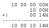
Since "ON" is parameter value 01H,
| F0 | 41 | 10 | 00 4D | 12 | 10 00 10 14 | 01 | ?? | F7 |
| (1) | (2) | (3) | (4) | (5) | address | data | checksum | (6) |
| (1) Exclusive status | (2) ID number (Roland) | (3) device ID(17) |
| (4) model ID (VK-8) | (5) command ID (DT1) | (6) EOX |
Next we calculate the checksum.
10H + 00H + 10H + 14H + 01H = 16 + 0 + 16 + 20 + 1 = 53 (sum)
53 (total) ÷ 128 = 0 (quotient)... 53 (remainder)
checksum = 128 - 53 (quotient) = 75 = 4BH
This means that the message transmitted will be F0 41 10 00 4D 12 10 00 10 14 01 4B F7.
Obtain preset organ parameter data for User Preset: 02 (RQ1).
The “Parameter address map” indicates that the starting address of USER: 02 is 20 01 00 00H, and that the offset address of Organ Parameter is 10 00H. Thus, the address is:
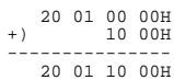
Since the size of the Performance Part is 00 00 00 1AH,
| F0 | 41 | 10 | 00 4D | 11 | 20 01 10 00 | 00 00 00 1A | ?? | F7 |
| (1) | (2) | (3) | (4) | (5) | address | data | checksum | (6) |
| (1) Exclusive status | (2) ID number (Roland) | (3) Device ID (17) |
| (4) Model ID (VK-8) | (5) Command ID (RQ1) | (6) EOX |
Next we calculate the checksum.
20H + 01H + 10H + 00H + 00H + 00H + 00H + 1AH =
32 + 1 + 16 + 0 + 0 + 0 + 0 + 26 = 75 (sum)
75 (total) ÷ 128 = 0 (product)... 75 (remainder)
checksum = 128 - 75 (remainder) = 53 = 35H
Thus, a message of F0 41 10 00 4D 11 20 01 10 00 00 00 00 1A 35 F7 would be transmitted.
MIDI Implementation Chart
Version : 1.00
| Function... | Transmitted | Recognized | Remarks | |||
| SEQUENCER MODE | KEYBOARD MODE | |||||
| Basic Channel | Default Changed | 1-161-16 | 1-161-16 | 1-16X | ||
| Mode | Default Messages Altered | Mode 3X********** | Mode 3X | Mode 1X | ||
| Note Number : True Voice | 30-101********** | 0-12736-96 (UPPER/LOWER)36-61 (PEDAL)0-127 (Other Tones) | 0-127*136-96 (UPPER/LOWER)36-61 (PEDAL)0-127 (Other Tones) | |||
| Velocity | Note On Note Off | O O | O O | O *1O | ||
| After Touch | Key's Channel's | X X | X X | X X | ||
| Pitch Bend | X | O *2 | X *3 | |||
| Control Change | 16, 3871011161770-7864100, 101 | X X *2X *4 *6 *7 *8 | O *2O *2O *2O *4O *6O *7 *8O *8 *9O | O *2O *2O *2O *2O *4O *6O *7 *8O *8 *9O | ModulationData entryVolumePanpotExpressionGeneral purpose controller 1General purpose controller 2Sound controllerHold 1RPN LSB, MSB | |
| Program Change | 0-63********** | O O *110-63 (Other Tones: 0-7) | Program No. 1-64 | |||
| System Exclusive | True Number | O | O | O | ||
| System Common | : Song Position: Song Select: Tune Request | X X X | X X X X | X X X | Processed as 0 | |
| System Real Time : Commands | X X | X X X | X X X | |||
| Aux Messages : All Sound Off: Reset All Controllers: Local On/Off: All Notes Off: Active Sensing: System Reset | O X X X X O X | O X O X X O X O X | X X X X | |||
| Notes | *1 The messages will be received as messages for sub keyboard part, regardless of their channel number.*2 Only OTHER TONES part*3 When OTHER TONES is assigned to KEYBOARD IN or PEDAL IN jack, the message of the OTHER TONES will be received.*4 The Messages will be received on the channel specified by Control MIDI Channel and Other Tones MIDI Channel.*5 Received Data will be handled in the same way as the EXPRESSION PEDAL jack of the VK-8 itself.*6 OTHER TONES Glide*7 Wheel Brake*8 The Messages will be received on the channel specified by Control MIDI Channel.*9 Harmonic Bar*10 Received Data will be handled in the same way as the HOLD PEDAL jack of the VK-8 itself.*11 Preset will be switched by received MIDI message. | |||||