
GI-20 - MIDI Controller ROLAND - Free user manual and instructions
Find the device manual for free GI-20 ROLAND in PDF.

| Product Type | MIDI Controller |
| Brand | Roland |
| Model | GI-20 |
| Dimensions (approx.) | 300 x 200 x 50 mm |
| Weight (approx.) | 1.5 kg |
| Power Supply | USB bus power or 9 V DC AC adapter |
| Power Consumption | 250 mA maximum |
| MIDI Connectors | 1 MIDI input, 1 MIDI output (5-pin DIN) |
| USB Interface | USB Type B for connection to a computer |
| Expression Pedal Input | 1 x 6.35 mm TRS jack |
| Main Functions | MIDI-USB interface, MIDI routing, filtering, message transformation |
| Compatibility | Windows, macOS, iOS via adapter |
| Included USB Cable Length | 1.5 m |
| Operating Temperature | 0 °C to 40 °C |
| Operating Humidity | 30% to 80% (non-condensing) |
| Case Material | ABS plastic |
| Maintenance and Cleaning | Wipe with a soft, dry cloth. Do not use solvents. |
| Safety | Do not expose to moisture, do not open the case. |
| Spare Parts | AC adapter, USB cable, user manual available on the Roland website |
| Repairability | No user-serviceable parts. Contact an authorized center. |
| Warranty | 2 years (parts and labor) |
| Country of Origin | China |
| FCC Model Number | GI-20 |
Frequently Asked Questions - GI-20 ROLAND
User questions about GI-20 ROLAND
0 question about this device. Answer the ones you know or ask your own.
Ask a new question about this device
Download the instructions for your MIDI Controller in PDF format for free! Find your manual GI-20 - ROLAND and take your electronic device back in hand. On this page are published all the documents necessary for the use of your device. GI-20 by ROLAND.
USER MANUAL GI-20 ROLAND
Thank you, and congratulations on your choice of the Roland GI-20 GK-MIDI Interface.
Before using this unit, carefully read the sections entitled:
"USING THE UNIT SAFELY" (page 2–3) and "IMPORTANT NOTES" (page 4).
These sections provide important information concerning the proper operation of the unit. Additionally, in order to feel assured that you have gained a good grasp of every feature provided by your new unit, owner's manual should be read in its entirety. The manual should be saved and kept on hand as a convenient reference.
Main Features
The GI-20 is a multifunction GK-MIDI interface.
It takes the signals from the individual strings of the guitar or bass equipped with a divided pickup, analyzes each string's pitch and volume, and outputs the information as MIDI data. You can combine the GI-20 with a MIDI sound module and use the setup as a guitar synthesizer, or connect it to a computer and use it as an input tool for sequencers or similar applications.
● Compatible with guitars and basses.
● Features internal patch memory, allowing you to store a variety of different settings.
- You can connect an expression pedal (the optional EV-5) or foot switch to (the optional FS-5U) adjust volume and pitch, hold notes, and control other aspects of performances.
- The GI-20 comes equipped with a USB connector. Using a single cable, you can connect the unit to a computer to easily input data and play performances.
* USB, short for Universal Serial Bus, is a type of interface for connecting computers to a wide variety of peripheral devices.
● The GI-20 also features a built-in chromatic tuner for fast, accurate tuning.
- The unit supports the use of a variety of playing techniques, including finger picking and tapping. And it gives you the most natural expression, matching your playing technique.
Copyright © 2003 ROLAND CORPORATION
All rights reserved. No part of this publication may be reproduced in any form without the written permission of ROLAND CORPORATION.

USING THE UNIT SAFELY
INSTRUCTIONS FOR THE PREVENTION OF FIRE, ELECTRIC SHOCK, OR INJURY TO PERSONS
About ⚠️ WARNING and ⚠️ CAUTION Notices
| ⚠ WARNING | Used for instructions intended to alert the user to the risk of death or severe injury should the unit be used improperly. |
| ⚠ CAUTION | Used for instructions intended to alert the user to the risk of injury or material damage should the unit be used improperly.* Material damage refers to damage or other adverse effects caused with respect to the home and all its furnishings, as well to domestic animals or pets. |
About the Symbols
| The △ symbol alerts the user to important instructions or warnings. The specific meaning of the symbol is determined by the design contained within the triangle. In the case of the symbol at left, it is used for general cautions, warnings, or alerts to danger. | |
| The ⊙ symbol alerts the user to items that must never be carried out (are forbidden). The specific thing that must not be done is indicated by the design contained within the circle. In the case of the symbol at left, it means that the unit must never be disassembled. | |
| The ● symbol alerts the user to things that must be carried out. The specific thing that must be done is indicated by the design contained within the circle. In the case of the symbol at left, it means that the power-cord plug must be unplugged from the outlet. |
ALWAYS OBSERVE THE FOLLOWING
WARNING
- Before using this unit, make sure to read the instructions below, and the Owner's Manual.
- Do not open (or modify in any way) the unit or its AC adaptor.
- Do not attempt to repair the unit, or replace parts within it (except when this manual provides specific instructions directing you to do so). Refer all servicing to your retailer, the nearest Roland Service Center, or an authorized Roland distributor, as listed on the “Information” page.
- Never use or store the unit in places that are:
- Subject to temperature extremes (e.g., direct sunlight in an enclosed vehicle, near a heating duct, on top of heat-generating equipment); or are
- Damp (e.g., baths, washrooms, on wet floors); or are
- Humid; or are
- Exposed to rain; or are
- Dusty; or are
- Subject to high levels of vibration.
- Make sure you always have the unit placed so it is level and sure to remain stable. Never place it on stands that could wobble, or on inclined surfaces.
- Be sure to use only the AC adaptor supplied with the unit. Also, make sure the line voltage at the installation matches the input voltage specified on the AC adaptor's body. Other AC adaptors may use a different polarity, or be designed for a different voltage, so their use could result in damage, malfunction, or electric shock.


WARNING
- Do not excessively twist or bend the power cord, nor place heavy objects on it. Doing so can damage the cord, producing severed elements and short circuits. Damaged cords are fire and shock hazards!

- Do not allow any objects (e.g., flammable material, coins, pins); or liquids of any kind (water, soft drinks, etc.) to penetrate the unit.

- Immediately turn the power off, remove the AC adaptor from the outlet, and request servicing by your retailer, the nearest Roland Service Center, or an authorized Roland distributor, as listed on the "Information" page when:

- The AC adaptor or the power-supply cord has been damaged; or
- If smoke or unusual odor occurs
- Objects have fallen into, or liquid has been spilled onto the unit; or
- The unit has been exposed to rain (or otherwise has become wet); or
- The unit does not appear to operate normally or exhibits a marked change in performance.
- In households with small children, an adult should provide supervision until the child is capable of following all the rules essential for the safe operation of the unit.

- Protect the unit from strong impact. (Do not drop it!)

WARNING
- Do not force the unit's power-supply cord to share an outlet with an unreasonable number of other devices. Be especially careful when using extension cords—the total power used by all devices you have connected to the extension cord's outlet must never exceed the power rating (watts/amperes) for the extension cord. Excessive loads can cause the insulation on the cord to heat up and eventually melt through.

- Before using the unit in a foreign country, consult with your retailer, the nearest Roland Service Center, or an authorized Roland distributor, as listed on the “Information” page.

- DO NOT play a CD-ROM disc on a conventional audio CD player. The resulting sound may be of a level that could cause permanent hearing loss. Damage to speakers or other system components may result.

CAUTION
- The unit and the AC adaptor should be located so their location or position does not interfere with their proper ventilation.

- Always grasp only the output plug or the body of the AC adaptor when plugging into, or unplugging from, this unit or an outlet.

- Any accumulation of dust between the AC adaptor and the power outlet can result in poor insulation and lead to fire. Periodically wipe away such dust with a dry cloth. Also, disconnect the power plug from the power outlet whenever the unit is to remain unused for an extended period of time.

- Try to prevent cords and cables from becoming entangled. Also, all cords and cables should be placed so they are out of the reach of children.

- Never climb on top of, nor place heavy objects on the unit.

- Never handle the AC adaptor body, or its output plugs, with wet hands when plugging into, or unplugging from, an outlet or this unit.

- Before moving the unit, disconnect the AC adaptor and all cords coming from external devices.

- Before cleaning the unit, turn off the power and unplug the AC adaptor from the outlet.

- Whenever you suspect the possibility of lightning in your area, disconnect the AC adaptor from the outlet.

- Should you remove the rubber feet, make sure to put them in a safe place out of children's reach, so there is no chance of them being swallowed accidentally.

For the U.K.
IMPORTANT: THE WIRES IN THIS MAINS LEAD ARE COLOURED IN ACCORDANCE WITH THE FOLLOWING CODE.
BLUE: NEUTRAL
BROWN: LIVE
As the colours of the wires in the mains lead of this apparatus may not correspond with the coloured markings identifying the terminals in your plug, proceed as follows:
The wire which is coloured BLUE must be connected to the terminal which is marked with the letter N or coloured BLACK. The wire which is coloured BROWN must be connected to the terminal which is marked with the letter L or coloured RED. Under no circumstances must either of the above wires be connected to the earth terminal of a three pin plug.
In addition to the items listed under “USING THE UNIT SAFELY” on page 2–3, please read and observe the following:
Power Supply
- Do not use this unit on the same power circuit with any device that will generate line noise (such as an electric motor or variable lighting system).
- The AC adaptor will begin to generate heat after long hours of consecutive use. This is normal, and is not a cause for concern.
- Before connecting this unit to other devices, turn off the power to all units. This will help prevent malfunctions and/or damage to speakers or other devices.
Placement
- Using the unit near power amplifiers (or other equipment containing large power transformers) may induce hum. To alleviate the problem, change the orientation of this unit; or move it farther away from the source of interference.
- This device may interfere with radio and television reception. Do not use this device in the vicinity of such receivers.
- Noise may be produced if wireless communications devices, such as cell phones, are operated in the vicinity of this unit. Such noise could occur when receiving or initiating a call, or while conversing. Should you experience such problems, you should relocate such wireless devices so they are at a greater distance from this unit, or switch them off.
- When moved from one location to another where the temperature and/or humidity is very different, water droplets (condensation) may form inside the unit. Damage or malfunction may result if you attempt to use the unit in this condition. Therefore, before using the unit, you must allow it to stand for several hours, until the condensation has completely evaporated.
Maintenance
- For everyday cleaning wipe the unit with a soft, dry cloth or one that has been slightly dampened with water. To remove stubborn dirt, use a cloth impregnated with a mild, non-abrasive detergent. Afterwards, be sure to wipe the unit thoroughly with a soft, dry cloth.
- Never use benzine, thinners, alcohol or solvents of any kind, to avoid the possibility of discoloration and/or deformation.
Additional Precautions
- Use a reasonable amount of care when using the unit's buttons, sliders, or other controls; and when using its jacks and connectors. Rough handling can lead to malfunctions.
- Never strike or apply strong pressure to the display.
- When connecting / disconnecting all cables, grasp the connector itself—never pull on the cable. This way you will avoid causing shorts, or damage to the cable's internal elements.
- To avoid disturbing your neighbors, try to keep the unit's volume at reasonable levels (especially when it is late at night).
- When you need to transport the unit, package it in the box (including padding) that it came in, if possible. Otherwise, you will need to use equivalent packaging materials.
- Use only the specified expression pedal (EV-5; sold separately). By connecting any other expression pedals, you risk causing malfunction and/or damage to the unit.
Handling CD-ROMs
- Avoid touching or scratching the shiny underside (encoded surface) of the disc. Damaged or dirty CD-ROM discs may not be read properly. Keep your discs clean using a commercially available CD cleaner.
* Microsoft and Windows are registered trademarks of Microsoft Corporation.
* Windows® 98 is known officially as: "Microsoft® Windows® 98 operating system."
* Screen shots in this documents are reprinted with permission from Microsoft Corporation.
* Windows® 2000 is known officially as: "Microsoft® Windows® 2000 operating system."
* Windows® Me is known officially as: "Microsoft® Windows® Millennium Edition operating system."
* Windows® XP is known officially as: "Microsoft® Windows® XP operating system."
* Apple and Macintosh are registered trademark of Apple Computer, Inc.
* MacOS is a trademark of Apple Computer, Inc.
* All product names mentioned in this document are trademarks or registered trademarks of their respective owners.
* OMS is a registered trademark of Opcode Systems, Inc.
* FreeMIDI is a trademark of Mark of the Unicorn, Inc.
USING THE UNIT SAFELY ...... 2
IMPORTANT NOTES ...... 4
Panel Descriptions ...... 6
Front Panel....6
Rear Panel....7
Signal Flow 8
Preparations to Make Before Performing ... 9
Items to Have On Hand....9
Installing the Divided Pickup on the Guitar or Bass......9
About MIDI....9
Connection Examples ....10
Selecting the Guitar or Bass ....10
Chapter 1 Try Playing Some Sounds ..... 11
Playing Sounds from a Sound Module....11
Connections....11
Turning On the Power....11
Adjusting the Input Sensitivity (SENSITIVITY)......11
Selecting Patches ...... 12
Setting the MIDI Channel (MIDI CHANNEL)....14
Setting the Control Channel (CTL CH)....15
Performing on the Guitar....16
Connecting to a Computer....17
Setting the MIDI Port....17
Setting the MIDI Data Path (MIDI PLAYBACK) ......17
Chapter 2 Creating Your Own Settings (Patches)... 18
Calling Up the Input Sensitivity Settings....18
Setting the Feeling of the Performance (PLAY FEEL)......18
Setting the Pedal and Switch Functions (ASSIGN) ......19
Shifting the Pitch of the Sound (TRANSPOSE) ......23
Setting the Range in Which Pitches Are Changed (BEND RANGE) 23
Switching Sounds on External Devices (PRG CHANGE) 25
Muting Specific Strings (STRING MUTE) ......26
Storing the Settings (WRITE) 26
Copying Patches 27
Chapter 3 Convenient Functions Featured by the GI-20.... 28
Tuning (TUNER) 28
Preventing Transmission of Program Change Messages (PC MASK) 29
Saving the Patches and System Parameters to an External Device (BULK DUMP)....29
Receiving Saved Data Using MIDI (BULK LOAD (MIDI))......30
Receive Saved Data Through USB (BULK LOAD (USB))......31
Reducing the Size of a MIDI Pitch Bend Message (BEND DATA THIN) 31
Reducing the Amount of Control Change Data Transmitted (RECEIVE CONTROL CHANGE DATA THIN)....32
Limiting the Extent of the Bend Range (BEND RANGE MAX)....32
Selecting the Type of USB Driver....33
Chapter 4 Other Functions...... 34
Reset to Default Factory Settings (Factory Reset) ......34
Installing the Rack Mount Adaptor....34
Attaching the Rubber Feet....34
Chapter 5 Appendices ...... 35
Troubleshooting 35
Error Messages....37
Roland Exclusive Messages....38
MIDI Implementation......40
MIDI Implementation Chart......43
Specifications 44
Installing & Setup the Driver...... 45
Installing & Setting Up the Driver (Windows)......46
Installing & Setting Up the Driver (Macintosh).....59
Troubleshooting....65
Index 69
Conversions Used in This Manual
- Words in square brackets [ ] indicate panel buttons or knobs. (Example)
[WRITE]: WRITE button
● (p. **) indicates a reference page.
Panel Descriptions
Front Panel
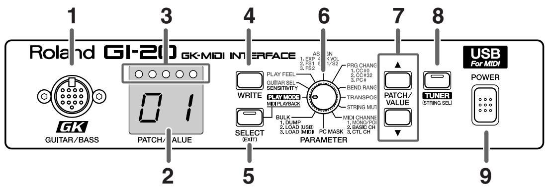
1. GK IN connector
Connect to the divided pickup using the GK cable included with the GI-20.
* Any questions you have regarding connections to the various GK-compatible guitars available on the market should be directed to the relevant guitar manufacturer or dealer.
2. LED display
This displays patch numbers, parameter values, and other information.
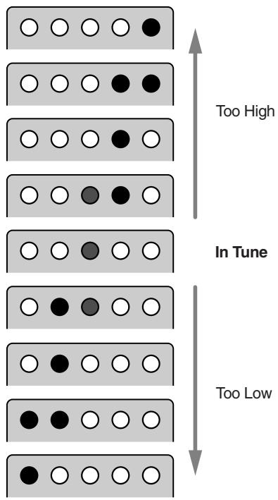
3. Tuner indicator
This indicates the tuning when the GI-20 is in Tuner mode.
When setting the sensitivity, this indicates the level.
4. WRITE button
Use this for writing patches (Write procedure; p. 26).
This is also used as the button to execute Factory Reset (p. 34) and Bulk Dump (p. 29).
5. SELECT (EXIT) button
Use this button to undo the Write procedure (p. 26) and select functions and parameters.
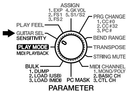
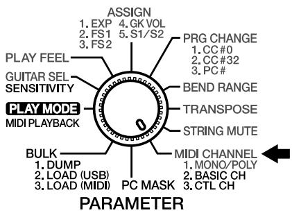
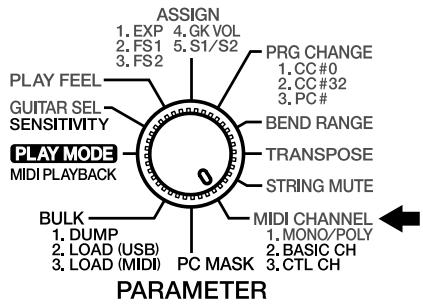
6. PARAMETER knob
This is used to select the parameter to be set.
7. PATCH/VALUE buttons
Use this to switch patches and change parameter values.
8. TUNER (STRING SEL) button
Press this when using the tuner function. Use this to select the strings when determining the parameter to set for each individual string.
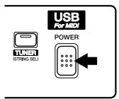
9. POWER switch
This turns the GI-20's power on and off.
Rear Panel
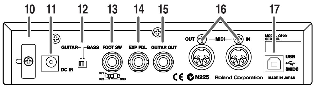
10.Cord Hook
Anchor the AC adaptor power cord here to prevent the adaptor from being disconnected accidentally.
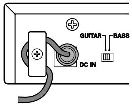
* To prevent the inadvertent disruption of power to your unit (should the plug be pulled out accidentally), and to avoid applying undue stress to the AC adaptor jack, anchor the power cord using the cord hook, as shown in the illustration.
11.AC Adaptor jack
The AC adaptor is connected here.

Never use any AC adaptor other than the one provided. Connecting any other adaptor may result in damage to the equipment.
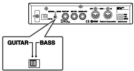
12.GUITAR/BASS switch
Switch this according to the instrument you are using. Switch to GUITAR if you are using a guitar; if using a bass, switch this to BASS.
* Note that the GI-20 may not operate properly if this setting is not correct.
13.FOOT SW jack
Connect an optional foot switch (such as the BOSS FS-5U) here.
14. EXP PDL (expression pedal) jack
Connect an optional expression pedal (such as the EV-5) here.
15.GUITAR OUT jack
This outputs the sound from the guitar or bass's normal pickup.
Connect this to a guitar amp or bass amp, or to an effects processor.
16. MIDI connector (IN/OUT)
This connector is used to connect an external MIDI device, allowing MIDI data to be transmitted and received.
17.USB connector
This connector is for connecting to a computer using a USB cable.

No USB cable is included with the GI-20. You will need to purchase a third-party USB cable separately.
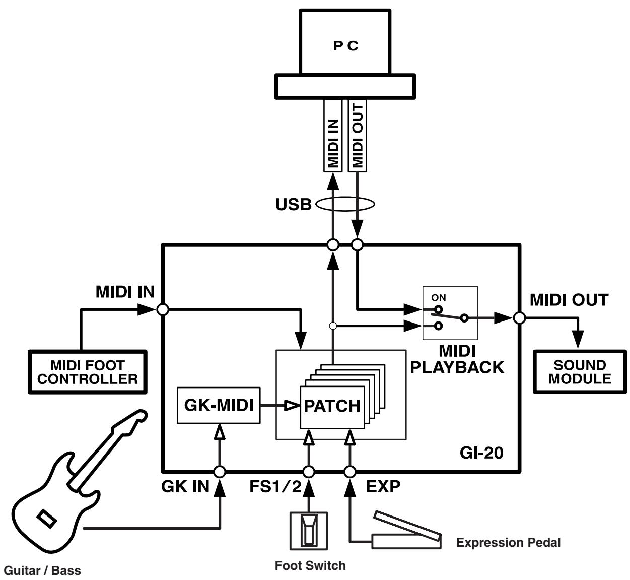
Signal Flow
flowchart
graph TD
    A["Guitar / Bass"] --> B["MIDI FOOT CONTROLLER"]
    B --> C["MIDI IN"]
    C --> D["USB"]
    D --> E["MIDI OUT"]
    E --> F["PCI"]
    F --> G["MIDI IN"]
    G --> H["USB"]
    H --> I["Multi-Channel"]
    I --> J["ON"]
    J --> K["MIDI PLAYBACK"]
    K --> L["MIDI OUT"]
    L --> M["SOUND MODULE"]
    M --> N["GI-20"]
    N --> O["EXPIRE"]
    O --> P["Foot Switch"]
    P --> Q["FS1/2"]
    Q --> R["GK-MIDI"]
    R --> S["PATCH"]
    S --> T["Gi-20"]
    T --> U["EXPIRE"]
    U --> V["Expression Pedal"]
    V --> W["Ground"]
Preparations to Make Before Performing
Although the GI-20 can be used with both guitars and basses, the descriptions here are based on the assumption you are using a guitar or six-string bass, and the numerals indicating the "strings" in the descriptions of settings and procedures correspond to the 1st through 6th strings of a guitar or regular six-string bass. If you are using a four-string or five-string bass, substitute the following numbers for those discussed in the manual.
| 1st String | → | --- |
| 2nd String | → | 1st String (G) |
| 3rd String | → | 2nd String (D) |
| 4th String | → | 3rd String (A) |
| 5th String | → | 4th String (E) |
| 6th String | → | 5th String (B) |
Items to Have On Hand
- To use the GI-20, you need a guitar or bass equipped with a pickup capable of separately outputting the signals for each individual string (a divided pickup).
● The GI-20 contains no internal sound generator, so you will need to use a separate MIDI sound module.
● Determine which other gear you will need by referring to the connection examples (p. 10).
Installing the Divided Pickup on the Guitar or Bass
First, attach the divided pickup to your instrument. Refer to the GK series Owner's Manual for instructions on installing the pickup.
Guitars That Cannot Be Used with the GK Series Pickup
While the compact design of the GK series pickup allows its installation on many different guitars, please note the following types of guitars on which it cannot be used:
• 12-string, pedal steel, and other specially strung guitars.
- Nylon-strung, gut-strung, and similar guitars; bass guitars.
- Guitars which, due to their physical design, lack the space for proper mounting of the GK series pickup.
MEMO
Several guitar manufacturers produce guitars that can be connected directly to the GR series with a GK cable, without the use of a GK series pickup. For more information, please ask your dealer or these guitar manufacturers.
About MIDI
MIDI stands for “Musical Instrument Digital Interface,” a worldwide standard that enables electronic instruments and peripherals to share information about performances, sound switching, and other functions. MIDI is a standard that is shared by a wide range of instruments from different manufacturers. For instance, you could use a MIDI controller from company A to play a sound module from company B or send data to a sequencer from company C.
MIDI Messages Handled by the GI-20
What follows is a list of some of the different types of MIDI messages that the GI-20 can handle.
- “Note On messages” provide information on what string was played, and its pitch and force.
- “Note Off messages” provide information on when a string stops vibrating.
- “Bend messages” provide information for changing the pitch smoothly, such as when bending, vibrato, or hammering.
- “Bank Select messages” and “Program Change messages” transmit commands for switching patches.
- “Control Change messages” provide information on changes in volume and effects.
- “System Exclusive (SysEx) messages” provide information for exchanging patch data with external instruments.
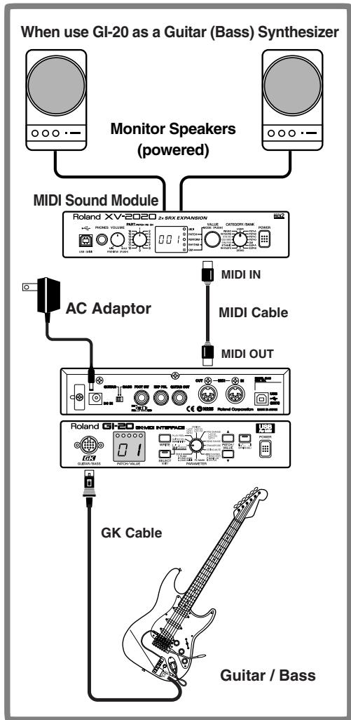
Connection Examples
When the guitar or bass is set up, connect the various devices as shown in the connection examples given in the figure.
* The GI-20 connects to sound modules only via MIDI, not USB, even if the sound module is USB equipped.
flowchart
graph TD
    A["When use GI-20 as a Guitar (Bass) Synthesizer"] --> B["Monitor Speakers (powered)"]
    B --> C["MIDI Sound Module"]
    C --> D["AC Adaptor"]
    D --> E["MIDI IN"]
    D --> F["MIDI Cable"]
    D --> G["MIDI OUT"]
    E --> H["GK Cable"]
    F --> H
    G --> H
    H --> I["Guitar / Bass"]
flowchart
graph TD
    A["Monitor Speakers (powered)"] --> B["MIDI Sound Module"]
    C["AC Adaptor"] --> D["MIDI IN"]
    D --> E["MIDI Cable"]
    E --> F["MIDI OUT"]
    F --> G["Rotand SV-2020 2+SRX EXPANSION"]
    G --> H["Computer"]
    I["GK Cable"] --> J["Guitar / Bass"]
    K["USB Cable"] --> L["* You will need to purchase a third-party USB cable separately."]
Selecting the Guitar or Bass
Set the GUITAR/BASS switch on the rear panel to match the instrument you are playing, in accordance with the range in which you are playing. Switch to GUITAR if you are using a guitar; if using a bass, switch this to BASS.
* Note that the GI-20 may not operate properly if this setting is not correct.
After the power is turned on, "Gt" (guitar) or "bG" (bass) flashes in the display for several seconds, allowing you to check the status of the GUITAR/BASS switch.
* This does not appear in the display when the GUITAR/BASS switch setting is changed at a later point.

GUITAR

BASS
* With the factory settings, all of the GI-20's patch settings are optimized for guitar. If you are using a bass, you can carry out a Factory Reset (p. 34), and change the settings so that they are suitable for the bass.
Chapter 1 Try Playing Some Sounds
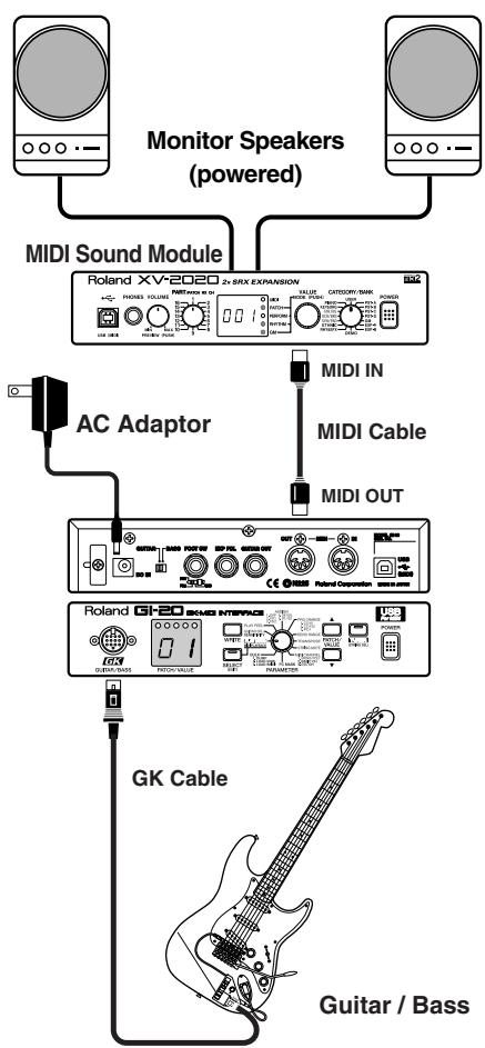
Playing Sounds from a Sound Module
This section explains how to connect the GI-20 to an external MIDI sound module and use it as a guitar synthesizer.
Connections
flowchart
graph TD
    A["Monitor Speakers (powered)"] --> B["MIDI Sound Module"]
    B --> C["Roland XV-2020 2x SRX EXPANSION"]
    C --> D["AC Adaptor"]
    D --> E["MIDI IN"]
    D --> F["MIDI Cable"]
    D --> G["MIDI OUT"]
    C --> H["Roland GI-20 SKM3 INTERFACE"]
    H --> I["GK Cable"]
    H --> J["Guitar / Bass"]
Connect the GI-20 and the external MIDI sound module as shown in the connection example in the figure.
Turning On the Power
Once your connections have been completed, turn on power to your various devices in the order specified. By turning on the devices in the wrong order, you risk causing malfunction and/or damage to speakers and other devices.
-
MIDI Sound Module
-
GI-20
* This unit is equipped with a protection circuit. A brief interval (a few seconds) after power up is required before the unit will operate normally.
- Monitor Speakers
Turning Off the Power
- Turn the volume down all the way on the MIDI sound module and monitor speakers or other device.
- Turn off the power to the power amp or other device.
- Turn off the power to the MIDI sound module and the GI-20.
Adjusting the Input Sensitivity (SENSITIVITY)
For best performance, it is important to adjust the input sensitivity for each individual string.
* You can store up to four sets of sensitivity settings (G1–G4), which means there is no need to readjust the settings from scratch each time you switch guitars and basses.
- Turn the PARAMETER knob to "GUITAR SEL."
- Press [PATCH/VALUE] to select the save destination for the sensitivity settings (G1–G4).

When G1 is selected
- Press [SELECT] to switch to the Sensitivity settings screen.
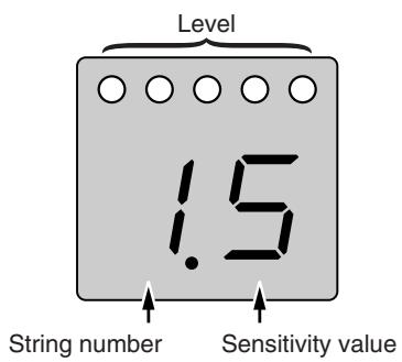
The left numeral indicates the string number, and the right numeral indicates the value of the sensitivity setting.
The level is indicated by the five indicators at the top of the display.
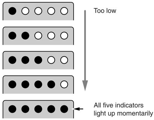
- Play each string individually with the maximum force to be used during the actual performance, and as you play the string, adjust the sensitivity with [PATCH/VALUE] until all five indicators light up momentarily.
- When you have finished making the settings, turn the PARAMETER to return to "PLAY MODE."
* Sensitivity is a system parameter. The settings are saved automatically when the memories (G1–G4) is changed or the PARAMETER knob is turned, even without the Write procedure being carried out. The settings in each of the memories (G1–G4) are applied to all patches. However, whichever of the sets G1–G4 to be used by each patch (Calling Up Input Sensitivity Settings" p. 18) is a patch parameter. Use the Write procedure to save these settings.
Selecting Patches
Switching the GI-20's patches allows you to change the values of settings instantly and perform using a wide variety of sounds.
What is a Patch?
The various information used in performing with the GI-20 is stored in sets called “patches.” In each patch you can store the settings values for the parameters described below, and switching these patches allows you to reproduce their settings instantly.
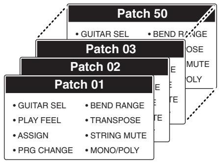
flowchart
graph TD
    A["Patch 01"] --> B["GUITAR SEL"]
    A --> C["PLAY FEEL"]
    A --> D["ASSIGN"]
    A --> E["PRG CHANGE"]
    F["Patch 02"] --> G["BEND RANGE"]
    F --> H["TRANSPOSE"]
    F --> I["STRING MUTE"]
    F --> J["MONO/POLY"]
    K["Patch 03"] --> L["BEND RANGE"]
    K --> M["POSE MUTE POLY"]
    K --> N["E"]
    K --> O["E"]
System Parameters and Patch Parameters
In contrast to the “patch parameters,” whose settings can be stored to each patch individually, parameters that are used by the GI-20 overall are called “system parameters.”
The following describes the different types of patch parameters and system parameters.
* Patch parameters are indicated in blue on the front panel.
System Parameters
- SENSITIVITY (p. 11)
- MIDI BASIC CH (p. 14)
- MIDI CTL CH (p. 15)
• PC MASK (p. 29) - MASTER TUNE (p. 28)
System parameters are stored in the GI-20 when you turn the PARAMETER knob after making changes to the settings.
* The MIDI BASIC CH and MIDI CTL CH parameters are also stored in the GI-20 when you press [SELECT] after making changes to the settings.
• MIDI PLAYBACK (p. 17)
• BEND DATA THIN (p. 31)
- RECEIVE CONTROL CHANGE DATA THIN (p. 32)
• BEND RANGE MAX (p. 32)
• USB DRIVER TYPE (p. 33)
These parameters are saved to the GI-20 the moment you change the settings values.
Patch Parameters
• GUITAR SEL (p. 18)
- PLAY FEEL (p. 18)
- ASSIGN (p. 19)
• PRG CHANGE (p. 25)
• BEND RANGE (p. 23)
• TRANSPOSE (p. 23)
• STRING MUTE (p. 26)
• MONO/POLY (p. 14)
With patch parameters, the Write procedure (p. 26) is used to save the settings values to individual patches after changes are made to the settings.
How to Switch Patches
Switch patches by pressing [PATCH/VALUE] in "Play mode" (p. 16).
● Each time you press [PATCH/VALUE ▲], the patch numbers are switched one at a time in ascending order, from 01 on up to 50.
● Each time you press [PATCH/VALUE ▼], the patch numbers are switched one at a time in descending order, from 50 down to 01.
When Not Switching Patches
With the GI-20, patches can only be switched in Play mode. When switching patches, turn the PARAMETER knob to return to Play mode.
Each of the GI-20's patches at the time the GI-20 is initially purchased is set for compatibility with GM sound modules.
Setting the sound module to GM mode when using a GM-compatible sound module allows you to enjoy a variety of sounds with the GI-20, just as at the time it was purchased.
MEMO
GM (General MIDI) is a set of recommended standards covering the way sounds are played by MIDI sound module, the arrangement of internal sound lists, and other aspects involving production of sound with sound generators. GM-compatible MIDI sound generating devices are called GM sound modules, and these devices are capable of reproducing essentially the same musical performance, regardless of the manufacturer or type of device.
About the Display
The following information is displayed when the GI-20 is in Play mode.

Lights up when the settings are changed.
Flashes while data is being stored.
When the content displayed is three or more digits long, the displayed is scrolled as shown below.
(Ex.) 440.0 Hz

Setting the Transmission Mode (MONO/POLY)
The GI-20 features two kinds of modes to transmit MIDI messages.
flowchart
graph LR
    A["1st"] --> B["Basic Channel"]
    C["2nd"] --> D["Basic Channel +1"]
    E["3rd"] --> F["Basic Channel +2"]
    G["4th"] --> H["Basic Channel +3"]
    I["5th"] --> J["Basic Channel +4"]
    K["6th"] --> L["Basic Channel +5"]
    M["Sound Module"] --> N["MONO"]
flowchart
graph LR
    A["1st"] --> B["Basic Channel"]
    C["2nd"] --> B
    D["3rd"] --> B
    E["4th"] --> B
    F["5th"] --> B
    G["6th"] --> B
    H["String"] --> B
    B --> I["Sound Module"]
* With the factory settings, all patches are set to MONO MODE.
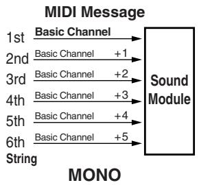
MONO (MONO MODE)
In this mode, each individual string uses a separate channel, thus totaling six channels.
Since each string uses a different MIDI channel, you can select different sounds for each string and continuously change the pitch data when using string bending and other special techniques with specific strings. However, this requires a multitimbral sound module.
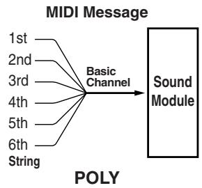
POLY (POLY MODE)
In this mode, the information for all six strings is transmitted over a single channel.
Since the MIDI messages for all six strings are transmitted over a single channel, it simplifies the settings for the sound module and reduces the number of MIDI channels used. However, options are more limited, for example, the same sound must be selected for all of the strings.
* In POLY mode, the Pitch Bend/Glide and Vibrato set in Assign (p. 19) function as follows.
When chords are played, Pitch Bend and Glide change in semitone steps and Vibrato does not function. These function normally when you play notes individually.
- Turn the PARAMETER knob to "MIDI CHANNEL."
- Press [SELECT] to select MONO/POLY.
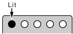
When MONO/POLY is selected, only the leftmost indicator lights up.
- Press [PATCH/VALUE] to select either MONO or POLY.


- To save the setting, carry out the Write procedure (p. 26).
* If you do not want to save the setting, turn the PARAMETER knob to return to "PLAY MODE."
- When you have finished making the settings, turn the PARAMETER knob to return to "PLAY MODE."
Setting the MIDI Transmit Channel (BASIC CH)
This sets the GI-20's MIDI Transmit channel (here called the "basic channel"). Set the MIDI channels as shown below according to whether the GI-20 is in POLY or MONO MODE.
When in POLY MODE
The performance data for all of the strings is transmitted over the Basic channel.
When in MONO MODE
1st String: Transmitted over the Basic channel.
2nd String: Transmitted over the Basic channel + 1.
3rd String: Transmitted over the Basic channel + 2.
:
6th String: Transmitted over the Basic channel + 5.
* With the factory settings, all patches are set to MONO MODE, and the Basic channel is set to Channel 1.
1. Turn the PARAMETER knob to "MIDI CHANNEL."
2. Press [SELECT] to select BASIC CHANNEL (BASIC CH).
When BASIC CHANNEL is selected, the two indicators at the left light up.
![ROLAND GI-20 - Press [SELECT] to select BASIC CHANNEL (BASIC CH). - 1](/content/2025/01/130723/images/d210352a9b6bb8bd5012a588478f97d521e2ba068ff4b03a33684a08f27b93ad.jpg)
3. Press [PATCH/VALUE] to select the Basic channel number.
![ROLAND GI-20 - Press [PATCH/VALUE] to select the Basic channel number. - 1](/content/2025/01/130723/images/c22de33a8279a7b26a00a6937e6916e7d6a6172062537162753a2a18c43cda3a.jpg)
* Since the six channels used in MONO MODE are consecutive, selecting Channel 12–16 as the Basic channel results in the MIDI channel number for the sixth string to exceed the allowable range of 1–16. In this case, the display flashes, and the performance data is sent by Channel 11–16.
4. When you have finished making the settings, turn the PARAMETER knob to return to "PLAY MODE."
* The Basic channel is a system parameter. It is saved automatically when the PARAMETER knob is turned, even without the Write procedure being carried out, and the settings values are applied to all patches.
Setting the Control Channel (CTL CH)
You can connect a foot controller or other such device to the MIDI IN connector to switch patches and perform other operations. In this case, you will need to set the “control channel” for reception of MIDI messages.
The control channel is a dedicated channel used only for receiving MIDI messages transmitted over the channel set to the same number. MIDI messages transmitted over other channels are disregarded.
* However, when the control channel is set to "OMNI mode" (Omni), MIDI messages are received regardless of the channel.
* With the factory settings, the control channel is set to "OMNI."
The GI-20's MIDI IN/OUT cannot be used under the following conditions.
- When MIDI IN and OUT are connected directly
- When the Soft Thru for the sequencer connected to MIDI IN/OUT is set to ON
In either case, the error message "E3" (p. 37) appears, and the GI-20 stops functioning normally.
The GI-20 can receive the following types of MIDI messages over the control channel.
Control Change
Control Change messages received over the control channel are transmitted over the basic channel (in MONO mode, all of the transmission channels for the strings).
Additionally, you can control the functions set in Assign (p.19) by assigning Control Changes to the general (assignable) controllers 3–8.
General Purpose Controller 3 (CC #18): Expression Pedal
General Purpose Controller 4 (CC #19): Foot Switch 1
General Purpose Controller 5 (CC #80): Foot Switch 2
General Purpose Controller 6 (CC #81): GK Volume
General Purpose Controller 7 (CC #82): S1 Switch
General Purpose Controller 8 (CC #83): S2 Switch
* These Control Change messages are not transmitted externally to other devices.
* For data corresponding to the Foot Switches 1/2 and S1/S2 Switches, 00h–3Fh are output as 00h (OFF), and 40h–7fh are output as 7fh (ON).
Chapter 1 Try Playing Some Sounds
Program Change
These messages switch the GI-20's patches.
Program Changes 0–49 correspond to Patches 1–50 on the GI-20.
* Program Changes 50–127 are disregarded.
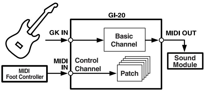
flowchart
graph TD
    A["MIDI Foot Controller"] -->|GK IN| B["+"]
    C["MIDI IN"] --> D["+"]
    B --> E["Basic Channel"]
    D --> F["Control Channel"]
    E --> G["+"]
    F --> H["Patch"]
    G --> I["MIDI OUT"]
    H --> I
    I --> J["Sound Module"]
    K["GI-20"] --> E
- Turn the PARAMETER knob to "MIDI CHANNEL."

- Press [SELECT] to select CONTROL CHANNEL (CTL CH).
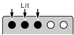
When CONTROL CHANNEL is selected, the three indicators at the left light up.
- Press [PATCH/VALUE] to select the Control channel number.
If you want to set the omni mode, select "oM."

- When you have finished making the settings, turn the PARAMETER knob to return to "PLAY MODE."
* The Control channel is a system parameter. It is saved automatically when the PARAMETER knob is turned, even without the Write procedure being carried out, and the settings values are applied to all patches.
Performing on the Guitar
When you have finished making the settings, try playing the guitar or bass to play sounds from the MIDI sound module.
- Turn the PARAMETER knob to "PLAY MODE."
- Play the guitar or bass.
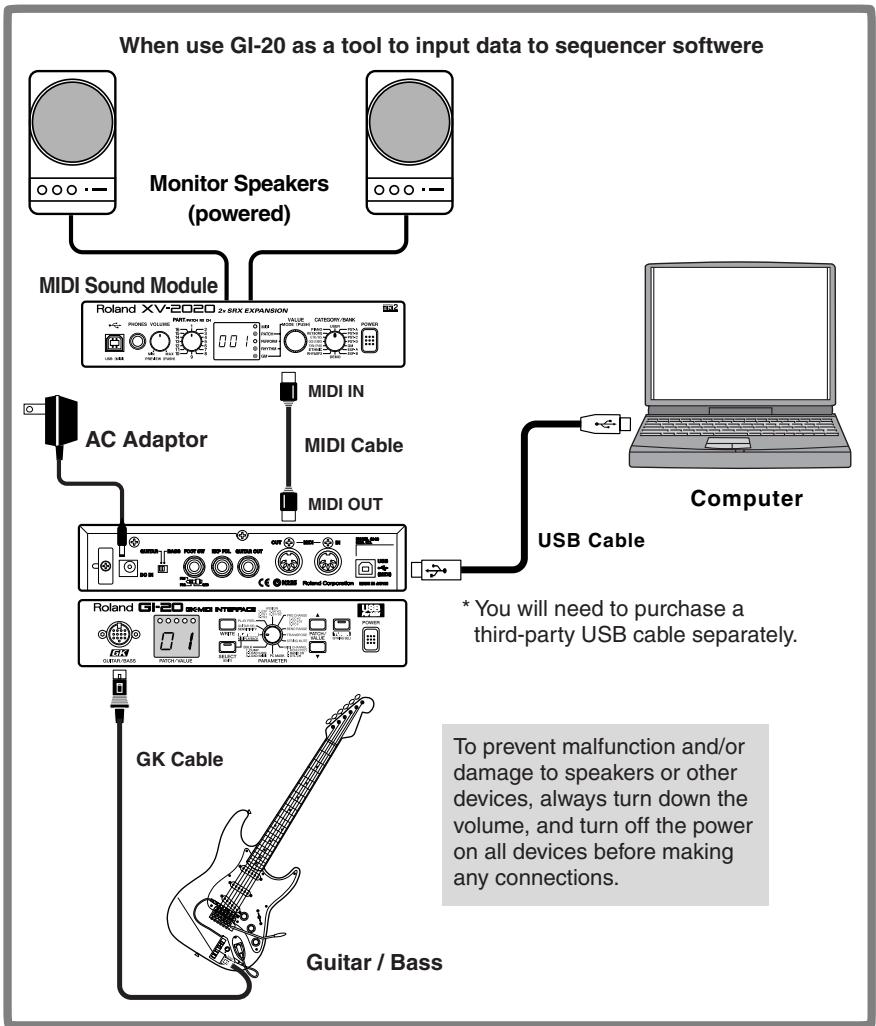
Connecting to a Computer
This section explains how to connect the GI-20 to your computer with a USB cable and use it as a tool to input data to sequencers and other devices.

No USB cable is included with the GI-20. You will need to purchase a third-party USB cable separately.

Do not press [SELECT] or connect (or disconnect) any device or cable to (or from) the USB connector during performances or while operating sequencers or other devices with the computer. This may cause malfunctioning of the computer or MIDI sound module.
* First, follow the instructions in "Installing & Setup the Driver" (p. 45) to install the GI-20 driver on your computer.
Setting the MIDI Port
This setting determines which MIDI data from the GI-20 is used by the applications on your computer.
In the application's MIDI device selection screen, select "Roland GI-20 MIDI IN" as the input device and "Roland GI-20 MIDI OUT" as the output device.
* For instructions on selecting the input device, refer to the owner's manual for the application you are using.
Roland GI-20 MIDI IN
This is the port used for inputting performance data to the GI-20 from your computer.
Input here is performance data from guitars and basses equipped with GK connectors.
Roland GI-20 MIDI OUT
This is the port used for outputting performance data to your computer from the GI-20.
When MIDI PLAYBACK is set to ON, the performance data the GI-20 receives from the computer is output as is from the GI-20's MIDI OUT connector (refer to "Setting the MIDI Data Path (MIDI PLAYBACK)" p. 17).
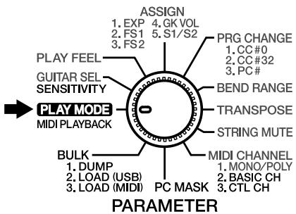
Setting the MIDI Data Path (MIDI PLAYBACK)
You can switch the MIDI messages that are output from MIDI OUT. Set MIDI PLAYBACK to "Off" when you want to output performance data input from the GK input directly from the MIDI OUT connector. When you want to output your computer's MIDI performance data from the GI-20's MIDI OUT connector, for example, if you want to play the computer's MIDI data through an external MIDI sound module, set this to "On."
1. Turn the PARAMETER knob to "PLAY MODE."
- Press [SELECT] to set MIDI PLAYBACK to "On" or "Off." [SELECT] is lit when this is set to "On"; when set to "Off," [SELECT] is unlit.
* MIDI PLAYBACK cannot be set to "On" unless the computer and the GI-20 are connected with a USB cable.
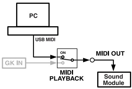
Signal Paths That Can Be Selected With MIDI PLAYBACK
When MIDI PLAYBACK is On: [SELECT] is lit
flowchart
graph TD
    A["PC"] -->|USB MIDI| B["MIDI PLAYBACK"]
    C["GK IN"] --> B
    B --> D["ON"]
    D --> E["O"]
    E --> F["MIDI OUT"]
    F --> G["Sound Module"]
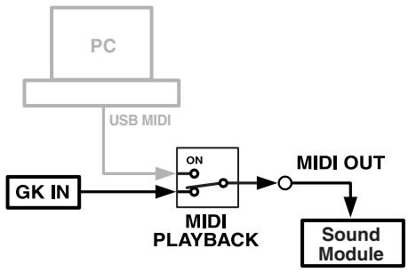
When MIDI PLAYBACK is Off: [SELECT] is unlit
flowchart
graph TD
    A["PC"] --> B["USB MIDI"]
    B --> C["MIDI PLAYBACK"]
    C --> D["MIDI OUT"]
    D --> E["Sound Module"]
    F["GK IN"] --> C
Chapter 2 Creating Your Own Settings (Patches)
Calling Up the Input Sensitivity Settings
Select input sensitivity settings appropriate for the guitar or bass you are using.
1. Turn the PARAMETER knob to "GUITAR SEL."

2. Press [PATCH/VALUE] to select a setting from G1 to G4.
You can make the input sensitivity settings for each of the sets G1–G4 (p. 11).
![ROLAND GI-20 - Press [PATCH/VALUE] to select a setting from G1 to G4. - 1](/content/2025/01/130723/images/acdae7902c6e35f71e2db83862e2948ad9d5a91244b571c8223bc858803c9f59.jpg)
When G1 is selected
3. If you want to save the settings, carry out the Write procedure (p. 26).
* If you do not want to save the settings, turn the PARAMETER knob to return to "PLAY MODE."
4. When you have finished making the settings, turn the PARAMETER knob to return to "PLAY MODE."
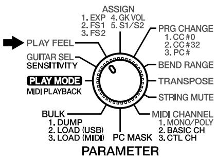
Setting the Feeling of the Performance (PLAY FEEL)
With guitars, in contrast to keyboards and similar instruments, the vibrating strings are touched directly, giving the player the ability to exert subtle control over the dynamics. To realize most faithfully this aspect of the guitar, you need to set a “performance response” for each patch that is appropriate both for the way the instrument is being played, as well as the sounds that are used.
These parameters are controlled by "PLAY FEEL." For example, you can get more natural dynamic expression by changing PLAY FEEL according to whether you are playing the strings with your fingers or using a pick.
1. Turn the PARAMETER knob to "PLAY FEEL."
2. Press [PATCH/VALUE] to change the value.
3. If you want to save the settings, carry out the Write procedure (p. 26).
* If you do not want to save the settings, turn the PARAMETER knob to return to "PLAY MODE."
4. When you have finished making the settings, turn the PARAMETER knob to return to "PLAY MODE."
The PLAY FEEL settings and their effects
nr: Normal

General picking, thus the standard setting for play.
Fi: Finger picking

The setting for when you want to perform with the feeling finger picking provides. Sensitivity is a little higher than Normal.
Hd: Hard picking

This setting is for those who pick rather hard, and the sensitivity is a little lower than Normal.
* When there is a problem with the guitar's arrangement, and the only places GK series pickup can be installed are too close to the strings, you may be able to improve the behavior with the settings in each patch.
SF: Soft picking

For picking that is a little weaker. Sensitivity is a little higher than Normal.
tP:Tapping play

When making use of many kinds of picking techniques, such as tapping play (or “right-hand play”), pulling-off, or hammering-on, this setting provides very stable sound expression. The range of power that can be expressed is a bit narrow.
nd: No dynamics

With this setting, no matter how hard or softly you play, you get uniform volume and tone. Use this setting with tones like Synth Lead or Organ when you want to transmit a feeling without expression.
Setting the Pedal and Switch Functions (ASSIGN)
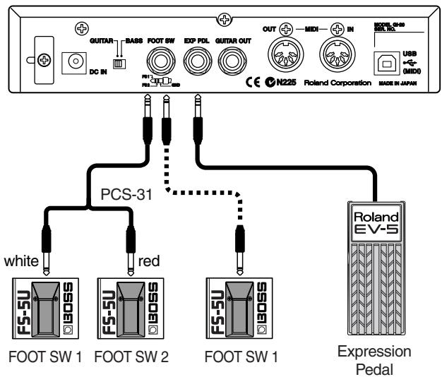
You can assign various functions to an expression pedal (the optional EV-5) or foot switch (the optional FS-5U) connected to the GI-20, or to the GK series pickup's S1, S2, and GK VOL.
* When connecting a foot switch (the optional BOSS FS-5U) to the FOOT SW jack, you can use the optional PCS-31 connection cable to connect two foot switches. Only FOOT SWITCH 1 is operational when just one FS-5U is connected to the FOOT SW jack.
flowchart
graph TD
    A["Device 1"] -->|PCS-31| B["White PS-5U 90SS"]
    A -->|PCS-31| C["Red PS-5U 90SS"]
    A -->|PCS-31| D["Red PS-5U 90SS"]
    A -->|PCS-31| E["Red PS-5U 90SS"]
    A -->|PCS-31| F["Red PS-5U 90SS"]
    A -->|PCS-31| G["Red PS-5U 90SS"]
    A -->|PCS-31| H["Red PS-5U 90SS"]
    A -->|PCS-31| I["Red PS-5U 90SS"]
    A -->|PCS-31| J["Red PS-5U 90SS"]
    A -->|PCS-31| K["Red PS-5U 90SS"]
    A -->|PCS-31| L["Red PS-5U 90SS"]
    A -->|PCS-31| M["Red PS-5U 90SS"]
    A -->|PCS-31| N["Red PS-5U 90SS"]
    A -->|PCS-31| O["Red PS-5U 90SS"]
    A -->|PCS-31| P["Red PS-5U 90SS"]
    A -->|PCS-31| Q["Red PS-5U 90SS"]
    A -->|PCS-31| R["Red PS-5U 90SS"]
    A -->|PCS-31| S["Red PS-5U 90SS"]
    A -->|PCS-31| T["Red PS-5U 90SS"]
    A -->|PCS-31| U["Red PS-5U 90SS"]
    A -->|PCS-31| V["Red PS-5U 90SS"]
    A -->|PCS-31| W["Red PS-5U 90SS"]
    A -->|PCS-31| X["Red PS-5U 90SS"]
    A -->|PCS-31| Y["Red PS-5U 90SS"]
    A -->|PCS-31| Z["Red PS-5U 90SS"]
    A -->|PCS-31| AA["Red PS-5U 90SS"]
    A -->|PCS-31| AB["Red PS-5U 90SS"]
    A -->|PCS-31| AC["Red PS-5U 90SS"]
    A -->|PCS-31| AD["Red PS-5U 90SS"]
    A -->|PCS-31| AE["Red PS-5U 90SS"]
    A -->|PCS-31| AF["Red PS-5U 90SS"]
    A -->|PCS-31| AG["Red PS-5U 90SS"]
    A -->|PCS-31| AH["Red PS-5U 90SS"]
    A -->|PCS-31| AI["Red PS-5U 90SS"]
    A -->|PCS-31| AJ["Red PS-5U 90SS"]
    A -->|PCS-31| AK["Red PS-5U 90SS"]
    A -->|PCS-31| AL["Red PS-5U 90SS"]
    A -->|PCS-31| AM["Red PS-5U 90SS"]
    A -->|PCS-31| AN["Red PS-5U 90SS"]
    A -->|PCS-31| AO["Red PS-5U 90SS"]
    A -->|PCS-31| AP["Red PS-5U 90SS"]
    A -->|PCS-31| AQ["Red PS-5U 90SS"]
    A -->|PCS-31| AR["Red PS-5U 90SS"]
    A -->|PCS-31| AS["Red PS-5U 90SS"]
    A -->|PCS-31| AT["Red PS-5U 90SS"]
    A -->|PCS-31| AU["Red PS-5U 90SS"]
    A -->|PCS-31| AV["Red PS-5U 90SS"]
    A -->|PCS-31| AW["Red PS-5U 90SS"]
    A -->|PCS-31| AX["Red PS-5U 90SS"]
    A -->|PCS-31| AY["Red PS-5U 90SS"]
    A -->|PCS-31| AZ["Red PS-5U 90SS"]
    A -->|PCS-31| BA["Red PS-5U 90SS"]
    A -->|PCS-31| BB["Red PS-5U 90SS"]
    A -->|PCS-31| BC["Red PS-5U 90SS"]
    A -->|PCS-31| BD["Red PS-5U 90SS"]
    A -->|PCS-31| BE["Red PS-5U 90SS"]
    A -->|PCS-31| BF["Red PS-5U 90SS"]
    A -->|PCS-31| BG["Red PS-5U 90SS"]
    A -->|PCS-31| BH["Red PS-5U 90SS"]
    A -->|PCS-31| BI["Red PS-5U 90SS"]
    A -->|PCS-31| BJ["Red PS-5U 90SS"]
    A -->|PCS-31| BK["Red PS-5U 90SS"]
    A -->|PCS-31| BL["Red PS-5U 90SS"]
    A -->|PCS-31| BM["Red PS-5U 90SS"]
    A -->|PCS-31| BN["Red PS-5U 90SS"]
    A -->|PCS-31| BO["Red PS-5U 90SS"]
    A -->|PCS-31| BP["Red PS-5U 90SS"]
    A -->|PCS-31| BQ["Red PS-5U 90SS"]
    A -->|PCS-31| BR["Red PS-5U 90SS"]
    A -->|PCS-31| BS["Red PS-5U 90SS"]
    A -->|PCS-31| BT["Red PS-5U 90SS"]
    A -->|PCS-31| BU["Red PS-5U 90SS"]
    A -->|PCS-31| BV["Red PS-5U 90SS"]
    A -->|PCS-31| BW["Red PS-5U 90SS"]
    A -->|PCS-31| BX["Red PS-5U 90SS"]
    A -->|PCS-31| BY["Red PS-5U 90SS"]
    A -->|PCS-31| BZ["Red PS-5U 90SS"]
    A -->|PCS-31| CA["Red PS-5U 90SS"]
    A -->|PCS-31| CB["Red PS-5U 90SS"]
    A -->|PCS-31| CC["Red PS-5U 90SS"]
    A -->|PCS-31| CD["Red PS-5U 90SS"]
    A -->|PCS-31| CE["Red PS-5U 90SS"]
    A -->|PCS-31| CF["Red PS-5U 90SS"]
    A -->|PCS-31| CG["Red PS-5U 90SS"]
    A -->|PCS-31| BH["Red PS-5U 90SS"]
    A -->|PCS-31| BI["Red PS-5U 90SS"]
    A -->|PCS-31| BJ["Red PS-5U 90SS"]
    A -->|PCS-31| BK["Red PS-5U 90SS"]
    A -->|pcs |

Set the polarity switch as shown below.
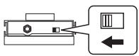
* Use only the specified expression pedal (EV-5; optional). By connecting any other expression pedals, you risk causing malfunction and/or damage to the unit.

Always make sure that the power to the GI-20 is turned off when connecting or disconnecting any foot switch or expression pedal. Connecting or disconnecting these devices while the GI-20's power is on may cause malfunction in the GI-20 or MIDI sound module.
1. Turn the PARAMETER knob to "ASSIGN."
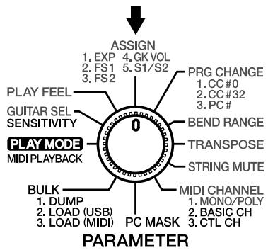
2. Press [SELECT] to select the parameter whose settings you want to change.
The display indicators light up as shown below according to the parameter being set.
![ROLAND GI-20 - Press [SELECT] to select the parameter whose settings you want to change. - 1](/content/2025/01/130723/images/97a130524da5fd0164540cda7e3e50893295b90a0b42b508f87c469feabacb61.jpg)
When the expression pedal is selected
![ROLAND GI-20 - Press [SELECT] to select the parameter whose settings you want to change. - 2](/content/2025/01/130723/images/dcccbdbe7ab6505a21008476b5656350b90b33817f9ce7fae3fe8b61f379480c.jpg)
When FOOT SWITCH 1 is selected
![ROLAND GI-20 - Press [SELECT] to select the parameter whose settings you want to change. - 3](/content/2025/01/130723/images/0f912be7f4247b46ba589c902735b70f5eac3c995245dec7fb4311d71c9e3451.jpg)
When FOOT SWITCH 2 is selected
![ROLAND GI-20 - Press [SELECT] to select the parameter whose settings you want to change. - 4](/content/2025/01/130723/images/32b5d1046a69be495c41fc603e1569d5e9143158e3df07be3b8af50791d46472.jpg)
When GK VOLUME is selected
![ROLAND GI-20 - Press [SELECT] to select the parameter whose settings you want to change. - 5](/content/2025/01/130723/images/297c0c776a7bf79168b4725ebcc16a28b563ba3bb39568cd8f3f09eb56df1aef.jpg)
When the S1/S2 switch is selected
3. Press [PATCH/VALUE] to change the value.
* For more on the settings values that can be selected, refer to the following section "Functions That Can Be Selected With Assign (ASSIGN)."
4. If you want to save the settings, carry out the Write procedure (p. 26).
* If you do not want to save the settings, turn the PARAMETER knob to return to "PLAY MODE."
5. When you have finished making the settings, turn the PARAMETER knob to return to "PLAY MODE."
Functions That Can Be Selected With ASSIGN
The following describes the functions that can be assigned to the controllers.
| Controller | function |
| Expression Pedal | CC#1-31, 64-95, Pitch Bend 1-6, Vibrato 1-4 |
| Foot Switch 1/2 | CC#1-31, 64-95, Patch Up, Patch Down, Octave Up, Octave Down, GR Hold1-3, Glide Up 1-8, Glide Down 1-8, Vibrato 1-4 |
| GK Volume | CC#1-31, 64-95 |
| S1/S2 Switch | Patch Up/Down, Octave Up/Down |
* When “POLY” is selected as the transmission mode, the Pitch Bend/Glide and Vibrato function as follows.
When BEND RANGE (p. 23) is set to anything other than Chromatic, Pitch Bend/Glide changes in semitone steps when chords are played, and Vibrato does not function. These function normally when you play notes individually.

When patches are switched, no signal is transmitted to restore the Control Change value transmitted with the previous patch. Therefore, if the same assign settings are used for both of the patches prior to and following the switch, the status of the controllers is carried over. However, if the assign settings are different for the patch you are switching to, you cannot restore the value for the Control Change transmitted with the earlier patch, so you will need to be aware of the following.
(Example)
The volume of a patch with CC 7 (Volume) assigned to the expression pedal is lowered to the minimum level. After this, if you switch to a patch with a different assign setting, since CC 7 (Volume) is not controlled in that patch, no sound is output, even when you press the expression pedal.
1–31, 64–95 (MIDI Control Change CC#1–31, CC#64–95)

(Ex.) CC 1
Transmits Control Change messages (#1–#31, #64–#95) from MIDI OUT. For more on the functions controlled with Control Change messages, refer to the “MIDI Implementation” (p. 40) and owner’s manual for the sound module you are using.
Pu: Patch Up

The patch number increases each time the switch is pressed.
Chapter 2 Creating Your Own Settings (Patches)
Pd: Patch Down

The patch number decreases each time the switch is pressed.
Pt: Patch Up/Down

The S1 switch is used for the Patch Down function and the S2 switch for the Patch Up function.
ou: Octave Up

All notes are raised an octave each time the switch is pressed. The pitches can be raised up to a maximum of two octaves.
* The pitches of notes currently being played are not altered.
od: Octave Down

All notes are lowered an octave each time the switch is pressed. The pitches can be lowered by a maximum of three octaves.
* The pitches of notes currently being played are not altered.
oC: Octave Up/Down

The S1 switch is used for the Octave Down function and the S2 switch for the Octave Up function.
* If notes transposed using the Octave Up/Down function are in registers that are unplayable with MIDI messages, the MIDI messages in the expressable range above or below that octave are transmitted.
H1: GR Hold 1

The sound being played are held while the foot switch is pressed.
By holding down the pedal, you can have the synth sound play without stopping, even as you change the position (the point at which the stringed is pressed against the guitar neck) or play discontinuous notes.
However, you cannot play two different sounds from the same string simultaneously.
H2: GR Hold 2

The sound being played is held the moment you press the foot switch, and continues to be held while you hold the pedal down.
The synth sound is not played during the hold, allowing you to hold chords played with the synth sound while you play the melody using the normal guitar sound.
H3: GR Hold 3

The sound being played is held the moment you press the foot switch, and continues to be held while you hold the pedal down.
Since you can still play the strings that aren't being held, it means you can hold chords played with the fifth and sixth strings using the synth sound, while you play the melody with the first through fourth strings, also using the synth sound.
* If the hold function is assigned to two foot switches, and both switches are pressed, the hold function for the foot switch pressed first takes priority, and the hold function for the foot switch pressed afterwards does not have any effect.
u1: Glide Up 1/d1: Glide Down 1

When the foot switch is pressed, the pitch changes continuously up (down) to a semi tone. Release the pedal to return to the original pitch.

u2: Glide Up 2/d2: Glide Down 2

When the foot switch is pressed, the pitch changes continuously up (down) to a whole tone. Release the pedal to return to the original pitch.

u3: Glide Up 3/d3: Glide Down 3

When the foot switch is pressed, the pitch changes continuously up (down) to a perfect fourth. Release the pedal to return to the original pitch.

Chapter 2 Creating Your Own Settings (Patches)
u4: Glide Up 4/d4: Glide Down 4

When the foot switch is pressed, the pitch changes continuously up (down) to a perfect fifth. Release the pedal to return to the original pitch.

u5–u8: Glide Up 5–8/d5–d8: Glide Down 5–8

When the foot switch is pressed, the pitch changes continuously up (down) to one octave. Release the pedal to return to the original pitch.

The higher the numeral set, the less time it takes for the change in pitch to be completed.


V1–V4: Vibrato 1–4

Pressing the pedal applies vibrato (an effect that changes the pitch cyclically). The effect deepens as the value is increased
* When using the expression pedal for this effect, the depth of the vibrato changes with the pedal angle.

b1: Pitch Bend 1

When the pedal is pressed, the pitch changes up to a perfect fourth (max.).
b2: Pitch Bend 2

When the pedal is pressed, the pitch changes up to a perfect fifth (max.).
b2: Pitch Bend 3

When the pedal is pressed, the pitch changes up to one octave (max.).
b4: Pitch Bend 4

When the pedal is pressed, the pitch changes down to a semi tone (max.).
b5: Pitch Bend 5

When the pedal is pressed, the pitch changes down to a whole tone (max.).
b6: Pitch Bend 6

When the pedal is pressed, the pitch changes down to one octave (max.).
* When “POLY” (p. 14) is selected as the transmission mode, the changes in pitch with Glide and Pitch Bend occur in semitone steps whenever two or more notes are played together, and Vibrato does not function.
* MIDI Pitch Bend messages are used for Glide and Pitch Bend. If the change in pitch exceeds the BEND RANGE (p. 23) set for Glide or Pitch Bend, the Glide or Pitch Bend is cut off and retriggered.
When using Glide or Pitch Bend, have the bend range set to 24 or Chromatic (C1–C3).
However, if BEND RANGE MAX (p. 32) is set to 12, Glide and Pitch Bend are retriggered if the pitch rises or falls an octave or more.
Shifting the Pitch of the Sound (TRANSPOSE)
On the GI-20, you can shift the pitch, in semitone steps, of what is output over MIDI relative to which is actually played. This transposition can be set individually for each string, and can be any amount from three octaves below the original pitch to two octaves above it. This function is called "TRANSPOSE."
This allows you to perform with open tuning, drop tuning, and other alternative tunings without having to actually change the guitar's own tuning.
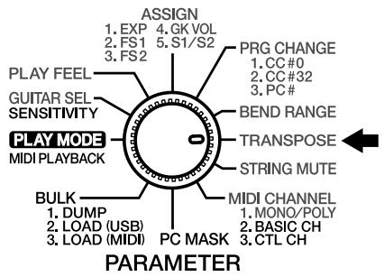
1. Turn the PARAMETER knob to "TRANSPOSE."
2. Press [TUNER (STRING SEL)] to select the string whose pitch you want to change.
The string number changes each time you press [TUNER (STRING)], cycling through ALL → 1 → 2 → 3 → 4 → 5 → 6 → ALL...
Select "ALL" if setting all of the strings to the same value.
3. After selecting the string whose pitch you want to change, press [PATCH/VALUE] to change the setting.
You can set the TRANSPOSE settings value in a range from -36 (down three octaves) to 24 (up two octaves).

-36 (-3 octaves)
![ROLAND GI-20 - After selecting the string whose pitch you want to change, press [PATCH/VALUE] to change the setting. - 2](/content/2025/01/130723/images/9c7b5d23bd0f512a8dfa405cd43dd45ac60fd9074533a20c07ac50da7935631a.jpg)
24 (+2 octaves)
* If notes whose pitches are changed using the TRANSPOSE function are in registers that are unplayable using MIDI messages, the MIDI messages in the expressable range above or below that octave are transmitted. For example, the sound of the bass's fourth string (E) lowered by three octaves cannot be played using MIDI messages, so the MIDI message for the note lowered two octaves is transmitted instead.
4. Repeat Steps 2 and 3 for any other strings you want to set.
- If you want to save the settings, carry out the Write procedure (p. 26).
* If you do not want to save the settings, turn the PARAMETER knob to return to "PLAY MODE."
- When you have finished making the settings, turn the PARAMETER knob to return to "PLAY MODE."
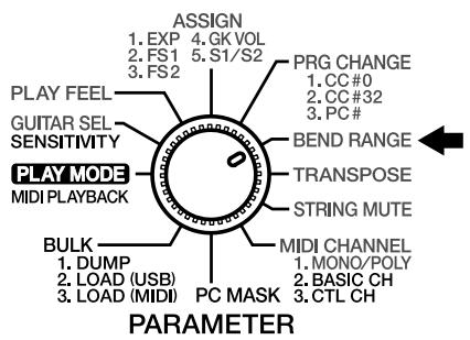
Setting the Range in Which Pitches Are Changed (BEND RANGE)
The GI-20 can send continuous pitch changes obtained with techniques such as bending, finger vibrato, tremolo bar usage, and sliding to an external device. This is done using MIDI Pitch Bend Change messages.
Setting Bend Range to as large a value as possible will help enable smooth pitch changes in a wider range. The settable range varies according to the receiving sound module. For equipment having a different settable width in the bend up and down directions, match the setting to the narrowest value.
About messages that notify the external MIDI instrument of the Bend Range and prompt change
The setting called Bend Range must be matched up on the sending and receiving instruments.
The GI-20 normally informs the external MIDI device of the Bend Range setting on the GI-20, and sends a message prompting change every time the patch is switched.
This means that the Bend Range value on the sound module can be set automatically every time the patch is changed simply by matching the maximum Bend Range value that can be set on the external MIDI sound module to the GI-20.
The messages used here are MIDI RPN (Registered Parameter Number) “Pitch Bend Sensitivity” messages (Control Change messages No. 100, No. 101, No. 6, and No. 38).
If you are using an external MIDI sound module which cannot recognize such messages, manually change Bend Range on the external device to the same value on the GI-20. Refer to the Owner's Manuals for the external sound module for information about its MIDI specifications.
* If the transmission mode is set to POLY, the MIDI messages transmitted when two or more strings are played simultaneously use semitone steps, which disallows string bending, slide, and certain other techniques. For more on the transmission mode settings, refer to “Setting the Transmission Mode” (p. 14).
* When Glide or Pitch Bend is selected as the foot switch or expression pedal Assign (p. 19) setting, and the BEND RANGE setting is within the range of the Glide or Pitch Bend range, the Glide or Pitch Bend will cut out and be retriggered.
Setting the Bend Range
- Turn the PARAMETER knob to "BEND RANGE."
- Press [TUNER (STRING)] to select the string whose bend range you want to change.
The string number changes each time you press [TUNER (STRING)], cycling through ALL → 1 → 2 → 3 → 4 → 5 → 6 → ALL...
Select "ALL" if setting all of the strings to the same value.
- Press [PATCH/VALUE] to change the value.
- Repeat Steps 2 and 3 for any other strings you want to set.
- If you want to save the settings, carry out the Write procedure (p. 26).
* If you do not want to save the settings, turn the PARAMETER knob to return to "PLAY MODE."
- When you have finished making the settings, turn the PARAMETER knob to return to "PLAY MODE."
Settings That Can Be Selected With BEND RANGE
1, 2, 4, 5, 7, 12, 24

(Ex.) 12 (1 octave)
One of the above values is selected (1 = semitone, 12 = one octave)
* You cannot select 24 when BEND RANGE MAX (p. 32) is set to 12.
With the GI-20, you can select “Chromatics” for the bend range. When the Chromatics (C1–C3) are selected, if you use string bending or other techniques that bend the guitar or bass pitch, the changes in pitch transmitted in the MIDI messages are made in semitone steps.
* A BEND RANGE value of 12 or 24 is transmitted when the chromatics are selected.
refer to "BEND RANGE MAX" (p. 32)
C1: Chromatic Type 1

When the pitch changes, the currently-heard sound will not stop; it will merely change in pitch. There is no separate attack sound when the pitch changes. This is a change similar to the one you hear with the slurred playing of a recorder.
C2: Chromatic Type 2

When the pitch changes, the sound for the new pitch will be started over, or "retriggered." Thus, whenever the pitch changes, you will hear a new attack. If the retrigger occurs as a string's vibration is trailing off (decaying), the retriggered note will play at an appropriately reduced volume.
C3: Chromatic Type 3

This is basically similar to “Type 2,” but differs in that the attenuation of the string's vibration is not reflected in the retriggered sound; instead, the retriggered sound is the same as that when the string was played originally.
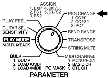
Switching Sounds on External Devices (PRG CHANGE)
You can transmit Bank Select messages (Control Change #0, #32) and Program Change messages by switching the GI-20's patches.
This enables you to switch sounds from external sound modules and patches of guitar effects processors.
When the transmission mode (p. 14) is set to MONO, these messages are transmitted separately for each individual string.
* The Bank Select messages and Program Change messages set here are not transmitted when PC MASK (p. 29) is set to "On."
1. Turn the PARAMETER knob to "PRG CHANGE."
2. Press [SELECT] to select the parameter that is to be changed.
The setting is changed each time you press [SELECT], cycling through Bank Select MSB (CC #0) → Bank Select LSB (CC #32) → Program Change in that sequence.
The display indicators light up as shown below according to the parameter being set.
![ROLAND GI-20 - Press [SELECT] to select the parameter that is to be changed. - 1](/content/2025/01/130723/images/a1b74ffbe0fc6461e81bff1bf4c1f69a284e5ca771f445a3b0a57754bab01bed.jpg)
Bank Select MSB (CC#0)
![ROLAND GI-20 - Press [SELECT] to select the parameter that is to be changed. - 2](/content/2025/01/130723/images/294a98277200892d949bb6b752e3095b667873b84222a4ddaa5346cf2d7c4791.jpg)
Bank Select LSB (CC#32)
![ROLAND GI-20 - Press [SELECT] to select the parameter that is to be changed. - 3](/content/2025/01/130723/images/2b89845856df92a5e98a884e0f8691ae8bda6088c074d39b266b2b2ee8e6c6eb.jpg)
Program Change
3. If you want to change the string settings, press [TUNER (STRING SEL)] to select the string numbers.
The string number changes each time you press [TUNER (STRING)], cycling through ALL → 1 → 2 → 3 → 4 → 5 → 6 → ALL...
![ROLAND GI-20 - If you want to change the string settings, press [TUNER (STRING SEL)] to select the string numbers. - 1](/content/2025/01/130723/images/6b6f9be60a10ba9eb80e381d1462324af824558b28a25c47f5cf77660d5daf45.jpg)
flowchart
graph LR
    A["ALL"] --> B["1-"]
    B --> C["2-"]
    C --> D["..."]
    D --> E["6-"]
* You cannot make separate settings for individual strings when the “transmission mode setting” (p. 14) is set to POLY. If you switch the transmission mode setting to POLY after making the settings for individual strings in MONO, the Bank Select and Program Change for the first string are transmitted.
4. Press [PATCH/VALUE] to change the value.
Repeat Steps 2–4 for other parameters you want to set.
![ROLAND GI-20 - Press [PATCH/VALUE] to change the value. - 1](/content/2025/01/130723/images/5e358ded138331489f5fd20f7c1a763e521863f245ad95882d64685f4acd06b4.jpg)
For Bank Select values (MSB: CC #0, LSB: CC #32), select Off and 0–127. For Program Change values (PC#), select Off and 1–128. When set to Off, no Bank Select or Program Change messages are transmitted, even when you change GI-20 patch numbers.
- If you want to save the settings, carry out the Write procedure (p. 26).
- When you have finished making the settings, turn the PARAMETER knob to return to "PLAY MODE."
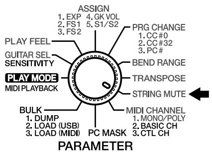
Muting Specific Strings (STRING MUTE)
1. Turn the PARAMETER knob to "STRING MUTE."
2. Press [TUNER (STRING SEL)] to select the string you want to mute.
The string number changes each time you press [TUNER (STRING)], cycling through ALL → 1 → 2 → 3 → 4 → 5 → 6 → ALL...
3. After you have selected the string number, press [PATCH/VALUE] to select "On."
Select "oF" (Off) if you do not want to mute the string.
![ROLAND GI-20 - After you have selected the string number, press [PATCH/VALUE] to select "On." - 1](/content/2025/01/130723/images/cd49f310cf11387285966d1d536bf8a52fe44999844919b1e5e5cbf9c2b1f0a7.jpg)
On
![ROLAND GI-20 - After you have selected the string number, press [PATCH/VALUE] to select "On." - 2](/content/2025/01/130723/images/5610240427412f2ef238682cb627bb4bd09ab3cc8e5e6c4bcd6c437c22619780.jpg)
Off
4. Repeat Steps 2 and 3 for any other strings you want to set.
5. If you want to save the settings, carry out the Write procedure (p. 26).
6. When you have finished making the settings, turn the PARAMETER knob to return to "PLAY MODE."
Storing the Settings (WRITE)
If you want to keep settings you have created (or changed), use the "Write procedure" to save the settings to a patch.
* Switching patches (p. 13) or turning off the power without first carrying out the Write procedure will cause the created settings to be deleted.
* System parameter (p. 12) settings are saved automatically when the PARAMETER knob is turned, even without the Write procedure being carried out.
* Except for when "TUNER" (p. 28) is selected, if the dot in the display is lit, it indicates that the patch settings have been changed.

1. Press [WRITE].
The current patch number flashes in the display.

Flash
2. Press [PATCH/VALUE] to select the save-destination patch.
* This step is unnecessary if you want to save the settings to the current patch.
* To cancel the Write procedure, press [SELECT (EXIT)].
3. Press [WRITE] once more.
The settings are stored in the save-destination patch.
* Note that once the Write procedure is carried out, any settings that had been stored in the save-destination patch are permanently lost.
Copying Patches
You can take the settings in a patch and copy them to a different patch.
- Confirm that the GI-20 is set to "PLAY MODE." If the GI-20 is not set to "PLAY MODE," then turn the PARAMETER knob to "PLAY MODE."
- Select the copy-source patch (refer to "How to Switch Patches" on p. 13).
- Press [WRITE]. The display flashes.

Flash
- Press [PATCH/VALUE] to select the copy-destination patch.
* To cancel the Copy procedure, press [SELECT (EXIT)]. - Press [WRITE] once more.
The settings are stored in the copy-destination patch.
* Note that once the Copy procedure is carried out, any settings that had been stored in the copy-destination patch are permanently lost.
Chapter 3 Convenient Functions Featured by the GI-20
Tuning (TUNER)
To achieve accurate pitch, use the GI-20's built-in tuner function to tune your guitar or bass.
-
Confirm that the GI-20 is set to "PLAY MODE." If the GI-20 is not set to "PLAY MODE," then turn the PARAMETER knob to "PLAY MODE."
-
Press [TUNER (STRING SEL)]. This turns on the Tuner function.
-
Press [SELECT]. The current reference pitch are indicated in the display. (Ex.) 440.0 Hz

- Press [PATCH/VALUE] to set the reference pitch. Range for this setting: 427.6 Hz–452.8 Hz (adjustable in units of 0.2 Hz).
* This was set to "440.0 Hz" when the unit left the factory.
* The reference pitch is a system parameter. It is saved automatically when the TUNER is turned off, even without the Write procedure being carried out, and the settings values are applied to all patches.
* The reference pitch is output from MIDI OUT as the RPN Channel Fine Tuning each time patches are switched.
- Press [SELECT].
- Play an open note on the string you want to tune.
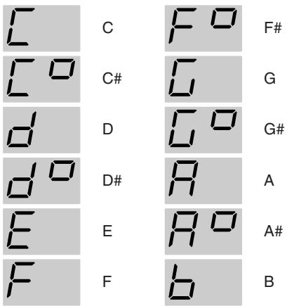
The name of the note closest to the pitch of the string you've played appears in the display.
* Be sure to play only the string to be tuned.
- As you watch the display, tune the string until only the center green indicator is lit.
- Repeat Steps 6 and 7 to tune all of the other strings.
- When you have finished tuning, press [TUNER (STRING)] to return to "PLAY MODE."
Preventing Transmission of Program Change Messages (PC MASK)
You can stop transmission of the Bank Select messages and Program Change messages set in “Switching Sounds on External Devices” (p. 25) for all patches.
1. Turn the PARAMETER knob to "PC MASK."
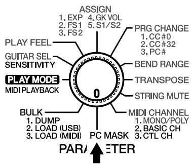
2. Press [PATCH/VALUE] to change the value.
![ROLAND GI-20 - Press [PATCH/VALUE] to change the value. - 1](/content/2025/01/130723/images/a7b960e4adcb6c9fe1c633f5a14c07f13055e044f21d4b16da6d7df80c2d7128.jpg)
![ROLAND GI-20 - Press [PATCH/VALUE] to change the value. - 2](/content/2025/01/130723/images/dea7d099966ef9373e4587bd1670a5069f64f7954c79533f94378481e2e569e4.jpg)
On:
Program Change messages and Bank Select messages are not transmitted.
Off:
The Program Change messages and Bank Select messages set in “Switching Sounds on External Devices” (p. 25) are transmitted.
3. When you have finished making the setting, turn the PARAMETER knob back to "PLAY MODE."
* PC MASK is a system parameter. It is saved automatically when the PARAMETER knob is turned, even without the Write procedure being carried out, and the settings values are applied to all patches.
Saving the Patches and System Parameters to an External Device (BULK DUMP)
Settings for all patches-as well as all system parameter settings-can be transferred in and out of the GI-20 using MIDI or USB. You can also save patches externally to equipment that can record MIDI data. For this kind of operation, the GI-20 uses MIDI messages called “System Exclusive messages.” Each System Exclusive message can be interpreted only by the device for which it is intended.
System Exclusive data sent from the GI-20 can be stored in a MIDI sequencer using the sequencer's realtime recording or bulk librarian function. You can also send/receive System Exclusive data directly from one GI-20 to another by connecting the two via MIDI.
MEMO
Transmitting the GI-20's data using Exclusive messages is referred to as "bulk dump," while using Exclusive messages to receive data is known as "bulk load."
1. Connect the GI-20's MIDI OUT to the MIDI IN on the external device.
Alternatively, use a USB cable to connect the GI-20 to your computer.
* Bulk data is output simultaneously from the MIDI OUT and USB connectors.
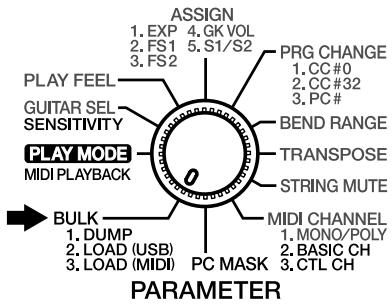
2. Turn the PARAMETER knob to "BULK."

- Confirm that "dP" (DUMP) is indicated in the display. If something else is indicated, press [SELECT (EXIT)] and select "dP" (DUMP).

- Begin recording on the external device being used to receive the data.
5. Press [WRITE].
The data is transmitted to the external device from the MIDI OUT and USB connectors.
The following appears in the display during transmission.

Flash
When the display changes back to "dP," the transmission is finished.
- If using a sequencer as the receiving device, stop recording.
- When you have finished the bulk dump, turn the PARAMETER knob back to "PLAY MODE."
Receiving Saved Data Using MIDI (BULK LOAD (MIDI))

Carrying out BULK LOAD automatically overwrites the settings data stored in the receiving device. Note that this will result in the loss of the data stored up to that time.
- Connect the external device's MIDI OUT to the MIDI IN on the GI-20.
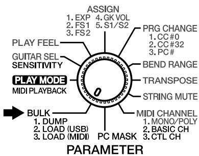
- Turn the PARAMETER knob to "BULK."
- Press [SELECT] to select "LM" (LOAD (MIDI)).

- Transmit the data from the external device.
The following appears in the display during reception.

When the display changes back to "LM," reception is finished.
- When you have finished the bulk load, turn the PARAMETER knob back to "PLAY MODE."
* If you change to another screen (by pressing [SELECT] or by turning the PARAMETER knob) while the data is being received, any data that's been received won't be loaded into the GI-20.
If necessary, start the Bulk Load procedure over from the beginning.
When the data is received correctly, the dot on the display will light.
Receive Saved Data Through USB (BULK LOAD (USB))

Carrying out BULK LOAD automatically overwrites the settings data stored in the receiving device. Note that this will result in the loss of the data stored up to that time.
- Use a USB cable to connect the computer and the GI-20.
* You cannot connect two GI-20s using a USB cable. Use a MIDI cable to connect GI-20s to each other. - Start up the application on your computer that will be handling the bulk data.
- Turn the PARAMETER knob to "BULK."
- Press [SELECT] to select "Lu" (LOAD (USB)).

- Transmit the data from the computer.
The following appears in the display during reception.

When the display changes back to "Lu," reception is finished.
- When you have finished the bulk load, turn the PARAMETER knob back to "PLAY MODE."
* If you change to another screen (by pressing [SELECT] or by turning the PARAMETER knob) while the data is being received, any data that's been received won't be loaded into the GI-20.
If necessary, start the Bulk Load procedure over from the beginning.
When the data is received correctly, the dot on the display will light.
Reducing the Size of a MIDI Pitch Bend Message (BEND DATA THIN)
The Bend Data Thin Function
With the guitar, the finger vibrato technique can be used to produce organic vibratos with amplitude and speed that can be freely varied-something that's very hard to do with a keyboard.
When creating sequencer data, the GI-20 records such finger vibratos, sliding, and tremolo bar usage as MIDI Pitch Bend messages. As a result of this, the MIDI performance message that is output contains a large number of Pitch Bend messages. In some cases, however, these Pitch Bend messages can greatly inflate the amount of data and exceed the sequencer's memory capacity.
The Bend Data Thin function is available to keep this to a minimum.
The amount of Pitch Bend messages that are sent can be reduced by using the Bend Data Thin function. Although the smoothness of pitch changes deteriorates, this can reduce the amount of MIDI data.
* With the factory settings, Bend Data Thin is set to "Off."
- Turn off the power to the GI-20.
- Hold down [WRITE] and turn on the power.
- Press [SELECT], causing the first two indicators on the left of the display to light up.
The first two indicators light when you select BEND DATA THIN.
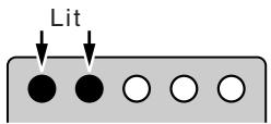
- Press [PATCH/VALUE] to select "On."
If you do not want to reduce the size of the Pitch Bend Message being transmitted, select "oF" (Off).

On

Off
- Turn the power off.
Reducing the Amount of Control Change Data Transmitted (RECEIVE CONTROL CHANGE DATA THIN)
Receive Control Change Data Thin Function
When the GI-20's transmission mode is set to "MONO" (p. 14), the Control Change messages received at MIDI IN are increased due to the output from all of the six strings. If a large number of Control Change messages are being received at the same time, it may cause data processing to stop, with the error message (p. 37) being displayed as a result. If this occurs, you can use the Receive Control Change Data Thin function to thin out some of the Control Change messages received at MIDI IN, while giving higher priority to the most recently received messages.
* With the factory settings, Receive Control Change Data Thin is set to "On."
- Turn off the power to the GI-20.
- Hold down [WRITE] and turn on the power.
- Press [SELECT], causing the first three indicators on the left of the display to light up.
The first three indicators on the left of the display light when you select RECEIVE CONTROL CHANGE DATA THIN.
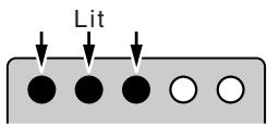
- Press [PATCH/VALUE] to select "On."
If you do not want to reduce the amount of data received, set this to "of" (Off).

On

Off
- Turn the power off.
Limiting the Extent of the Bend Range (BEND RANGE MAX)
Although the GI-20 has a maximum bend range setting of 24, unless the GI-20 and your sound module feature the same bend range settings, you may find that functions such as pitch bend and string bending do not work well.
However, some sound modules have only a narrow range of settings you can make. In such situations, use BEND RANGE MAX.
BEND RANGE MAX helps keep poor operation to a minimum by limiting the GI-20's bend range to that of the connected sound module.
For example, setting BEND RANGE MAX to 12 limits the maximum value for the BEND RANGE output by the GI-20 to 12.
* For more on your sound module's specifications, refer to the owner's manual that came with it.
* With the factory settings, this is set to "24."
* When BEND RANGE MAX is set to "12," the sound module is retriggered if the pitch is changed by an octave with pitch bend or glide.
Take note of this when Glide or Pitch Bend is assigned (p. 19) to the foot switch or expression pedal.
- Turn off the power to the GI-20.
- Hold down [WRITE] and turn on the power.
- Press [SELECT], causing the first four indicators on the left of the display to light up.
The first four indicators on the left of the display light when you select BEND RANGE MAX.
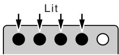
- Press [PATCH/VALUE] to select "12" or "24."
If you do not want to limit the bend range, set this to "24."

- Turn the power off.
Selecting the Type of USB Driver
When using the GI-20 when it is connected to a computer, you can select from two types of drivers.
* Be sure to set the GI-20's driver so that it matches the driver used by the computer. In some cases, the driver may not function properly.
SP: VENDER SPECIFIC:

The special driver on the CD-ROM included with the GI-20 is used, providing faster, more stable MIDI transmission. Normally, this is what you should use.
GE: GENERIC:

Use this setting when using the standard MIDI driver that came with your OS.
* With the factory settings, USB DRIVER is set to "VENDER SPECIFIC."
- Turn off the power to the GI-20.
- Hold down [WRITE] and turn on the power.
- Press [SELECT], causing only the leftmost indicator of the display to light up.
Only the leftmost indicator light when you select USB DRIVER TYPE.
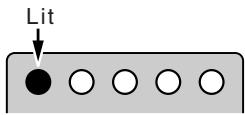
-
Press [PATCH/VALUE] to select "SP" or "GE."
-
Turn the power off.
The USB driver setting becomes effective the next time you turn on the GI-20.
Chapter 4 Other Functions
Reset to Default Factory Settings (Factory Reset)
The procedure for restoring the GI-20's internal settings to the state they were in when the unit left the factory is called a "Factory Reset." This procedure allows you to return the patch parameters for Patches 01–50, pickup sensitivity settings, MIDI transmission, and other system parameters to their original factory values.
Here, you can set the GUITAR/BASS switch to select patch content that is optimized for the use of either a guitar or bass.
* With the factory settings, this is set to patches that are optimized for the guitar.

The Factory Reset operation undoes any settings you have changed and discards any edits you have made to its patches. If you have settings or patches you wish to preserve, use the Bulk Dump operation (p. 29) to save them, before performing the Factory Reset operation.
- Turn off the power to the GI-20.
- Set GUITAR/BASS to match the instrument you are using (guitar or bass).
- Hold down [TUNER (STRING SEL)] and turn on the power.
"in" appears in the display.

Flash
* To cancel the procedure, turn off the power to the GI-20.
4. Press [WRITE].
"Wr" appears in the display and the dot in the display flashes, and Factory Reset is carried out.
![ROLAND GI-20 - Press [WRITE]. - 1](/content/2025/01/130723/images/3fddd5a8d8be73366d5cef6c669d85ea9fde479bfa9a9387bc4e1b05352ef07d.jpg)
Flash
When Factory Reset is completed, "oF" flashes in the display.
![ROLAND GI-20 - Press [WRITE]. - 2](/content/2025/01/130723/images/8946d89b93dcb460d4fca4625ae9edf8174bf358fcf8a0da50376e68a3e22a6e.jpg)
Never turn off the power while Factory Reset is in progress. Doing so may damage the unit.
5. Turn off the power to the GI-20.
Installing the Rack Mount Adaptor
When installing on the rack-mount adaptor (RAD-50; optional), use the screw (M4 x 8) included with the rack-mount adaptor.
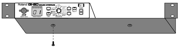
Screw (M4 x 8)
Attaching the Rubber Feet
If you are not going to be using a rack mount adaptor, attach the rubber feet as shown.
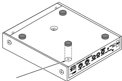
natural_image
Isometric line drawing of a rectangular electronic device with four circular ports and a central hub (no text or symbols)Affix the supplied rubber feet onto the bottom of the unit
Chapter 5 Appendices
Troubleshooting
If there is no sound or other operational problems occur, first check through the following solutions. If this does not resolve the problem, then contact your dealer or a nearby Roland service station.
The volume fluctuates from one string to another
☐ Are the "SENSITIVITY" settings correct for each string?
→ Adjust the settings as required. (p. 11)
☐ Is the GUITAR/BASS switch on the rear panel set correctly?
→ Switch to GUITAR if you are using a guitar; if using a bass, switch this to BASS. (p. 10)
Pitch doesn't rise when using Pitch Glide (or the expression pedal Pitch function)
☐ Functions that vary pitch continuously may experience a limited range of change during rising pitch due to the register.
If a limitation is encountered, use with a narrower width of change. (p. 22)
Pitch doesn't change smoothly
☐ Is "BEND RANGE" (p. 23) set to "Chromatic Type 1-3"?
→ Set BEND RANGE to anything other than Chromatic Type for patches that require continuous changes in pitch. (p. 23)
☐ Is data being sent in the Poly mode (p. 14)?
→ When transmitting in the Poly mode, pitch changes during chord performances are in semitone steps. Play with single notes, or use the Mono mode to send data.
☐ Is the Bend Data Thin function (p. 31) in use?
→ Using this function may result in a slight loss of smoothness when pitch changes, even during normal play. Do not use the Bend Data Thin function when it is not needed.
☐ Is BEND RANGE MAX (p. 32) or BEND RANGE (p. 23) set to anything other than 24?
→ With BEND RANGE MAX set to anything other than 24, if Glide Up/Down 5–8 or Pitch Bend 3 or 6 is used in Assign (p. 19), then changing the pitch by an octave causes retriggering. Set BEND RANGE MAX and BEND RANGE to 24.
☐ Is "BEND RANGE" (p. 23) set to "1" or "2"?
→ When matching with sending and receiving, use as large a value as possible.
The sound doesn't vary when the settings are changed
☐ Is the setting being changed one of the parameters that can be made independently for each string, and is the setting affecting only a particular string?
→ Use [TUNER (STRING)] to select "ALL."
No sound from the external sound module
Do the MIDI channels for sending and receiving match?
→ Make sure the MIDI channels match. (p. 14)
☐ The volume level of the external sound module may have been lowered by a MIDI Volume message (Control Change No. 7) sent from the GI-20.
→ Raise the volume on the GK series pickup.
☐ Make sure the volume on the GK series pickup or the expression pedal has not been turned down too low.
→ Use the controls to increase the volume.
☐ Is "STRING MUTE" (p. 26) set to "On"?
→ If "STRING MUTE" is set to "On", note messages cannot be transmitted. Please change it to "Off."
☐ The value of Bank Select in "PRG CHANGE" (p. 25) is set to the value that does not match the sound module.
→ Check the Patch setting on the GI-20 and the specifications of the Bank Select on the sound module.
The external sound module plays only one string (some strings can't be heard)
☐ Is the GI-20 using the Mono mode to send data to a sound module which cannot simultaneously receive data on six MIDI channels?
→ For such sound module, send data in the Poly mode. (p. 14)
Notes in a bass register not on the guitar/bass cannot be played
→ Output from MIDI OUT can be transposed as desired by changing the TRANSPOSE setting. (p. 23)
The pitch is wrong (out of tune with the guitar/bass)
☐ Is MIDI Bend Range the same for both sending and receiving?
→ If the pitch is off, adjust the BEND RANGE setting.
(p. 23)
☐ Is the GUITAR/BASS switch on the rear panel set correctly?
→ Switch to GUITAR if you are using a guitar; if using a bass, switch this to BASS. (p. 10)
Problems occur after switching GI-20 patches. For example, the connected sound module no longer produces sound, or the sound won't stop, or modulation is applied constantly and won't switch off.
☐ When patches are switched, no signal is transmitted to restore the Control Change value transmitted with the previous patch. Therefore, if the same assign settings are used for both of the patches prior to and following the switch, the status of the controllers is carried over. However, if the assign settings are different for the patch you are switching to, you cannot restore the value for the Control Change transmitted with the earlier patch. (p. 20)
The Note messages input to the sequencer don't look like the scale that is actually played
To start playing sounds rapidly and achieve smooth changes in pitch, the GI-20 transmits pitch as a combination of Note messages and Pitch Bend messages. This means that if only the Note messages are examined on the sequencer's microscope (event list) screen, the on-screen information may differ from what is actually performed.
→ If continuous pitch change is not required, you can create data that is displayed more faithfully by setting the BEND RANGE to “Chromatic Type 1–3.” (p. 23)
Error Messages
If you attempt an incorrect operation or if an operation could not be executed, the display will indicate an error message. Refer to this list and take the appropriate action.

Reason Reception of bulk data in the Bulk Load screen was immediately followed by reception of subsequent bulk data, so the data received after by the GI-20 could not be processed.
Action Switch the screen for a moment, then select the Bulk Load screen again and retransmit the bulk data. In case of transmitting the bulk data more than twice, please make sure that the previous data was firmly received and transmit another data.

Reason There was an error in the bulk data received in the Bulk Load screen.
Action Switch the screen for a moment, then select the Bulk Load screen again, and transmit the bulk data again after correcting the data to transmit to the GI-20.

Reason 1 The GI-20 stopped processing due to an attempt to transmit numerous MIDI messages from the GI-20 at one time. (The GI-20's MIDI IN/OUT connectors may be connected with a single MIDI cable.)
Action 1 Check the connections.
Reason 2 Soft Thru on the sequencer connected to the MIDI IN/OUT is set to ON.
Action 2 Set the sequencer's Soft Thru to OFF.

Reason The data transmitted from the GI-20's USB connector was not received by the connected computer, preventing the GI-20 from processing transmissions.
Action Confirm that the USB-connected device is capable of receiving the data properly.

Reason The GI-20's MIDI IN connector received many MIDI messages at once, and the GI-20 was unable to process the data.
Action Reduce the amount of MIDI data transmitted to the GI-20's MIDI IN.

Reason [SELECT] was pressed while exclusive data was being transmitted via the computer's USB connector, so the exclusive data could not be received properly.
Action The sound module or other device connected to the GI-20's MIDI OUT may not be operating correctly. Turn off the power to the sound module or other device, then turn it back on again.
Roland Exclusive Messages
1. Data Format for Exclusive Messages
Roland's MIDI implementation uses the following data format for all Exclusive messages (type IV):
| Byte | Description |
| F0H | Exclusive Status |
| 41H | Manufacturer ID (Roland) |
| DEV | Device ID |
| MDL | Model ID |
| CMD | Command ID |
| [BODY] | Main data |
| F7H | End of exclusive |
•MIDI status: F0H, F7H
An Exclusive message must be flanked by a pair of status codes, starting with a Manufacturer ID immediately after F0H (MIDI version 1.0).
•Manufacturer ID: 41H
The Manufacturer ID identifies the manufacturer of a MIDI instrument that sends an Exclusive message. Value 41H represents Roland's Manufacturer ID.
- Device ID: DEV
The Device ID contains a unique value that identifies individual devices in the implementation of several MIDI instruments. It is usually set to 00H-0FH, a value smaller by one than that of a basic channel, but value 00H-1FH may be used for a device with several basic channels.
- Model ID: MDL
The Model ID contains a value that identifies one model from another. Different models, however, may share an identical Model ID if they handle similar data.
The Model ID format may contain 00H in one or more places to provide an extended data field. The following are examples of valid Model IDs, each representing a unique model:
| 01H |
| 02H |
| 03H |
| 00H, 01H |
| 00H, 02H |
| 00H, 00H, 01H |
•Command ID: CMD
The Command ID indicates the function of an Exclusive message. The Command ID format may contain 00H in one or more places to provide an extended data field. The following are examples of valid Command IDs, each representing a unique function:
| 01H |
| 02H |
| 03H |
| 00H, 01H |
| 00H, 02H |
| 00H, 00H, 01H |
• Main data: BODY
This field contains a message to be exchanged across an interface. The exact data size and content will vary with the Model ID and Command ID.
2. Address-mapped Data Transfer
Address mapping is a technique for transferring messages conforming to the data format given in Section 1. It assigns a series of memory-resident records—waveform and tone data, switch status, and parameters, for example, to specific locations in a machine-dependent address space, thereby allowing access to data residing at the address a message specifies.
Address-mapped data transfer is therefore independent of models and data categories. This technique allows use of two different transfer procedures: one-way transfer and handshake transfer.
- One-way transfer procedure (See Section 3 for details.)
This procedure is suited to the transfer of a small amount of data. It sends out an Exclusive message completely independent of the receiving device's status.
Connection Diagram
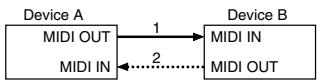
Connection at point 2 is essential for "Request data" procedures. (See Section 3.)
- Handshake-transfer procedure (This device does not use this procedure)
This procedure initiates a predetermined transfer sequence (handshaking) across the interface before data transfer takes place. Handshaking ensures that reliability and transfer speed are high enough to handle a large amount of data.
Connection Diagram
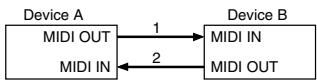
Connection at points 1 and 2 is essential.
Notes on the above procedures
* There are separate Command IDs for different transfer procedures.
* Devices A and B cannot exchange data unless they use the same transfer procedure, share identical Device ID and Model ID, and are ready for communication.
3. One-way Transfer Procedure
This procedure sends out data until it has all been sent and is used when the messages are so short that answerbacks need not be checked.
For longer messages, however, the receiving device must acquire each message in time with the transfer sequence, which inserts 20 milliseconds intervals.
Types of Messages
| Message | Command ID |
| Request data 1 | RQ1 (11H) |
| Data set 1 | DT1 (12H) |
- Request data #1: RQ1 (11H) (This device does not use this procedure)
This message is sent out when there is a need to acquire data from a device at the other end of the interface. It contains data for the address and size that specify designation and length, respectively, of data required.
On receiving an RQ1 message, the remote device checks its memory for the data address and size that satisfy the request.
If it finds them and is ready for communication, the device will transmit a "Data set 1 (DT1)" message, which contains the requested data. Otherwise, the device won't send out anything.
| Byte | Description |
| F0H | Exclusive Status |
| 41H | Manufacturer ID (Roland) |
| DEV | Device ID |
| MDL | Model ID |
| 11H | Command ID |
| aaH | Address MSB |
| | | | |
| | | | |
| LSB | |
| ssH | Size MSB |
| | | | |
| | | | |
| LSB | |
| sum | Check sum |
| F7H | End of exclusive |
* The size of the requested data does not indicate the number of bytes that will make up a DT1 message, but represents the address fields where the requested data resides.
* Some models are subject to limitations in data format used for a single transaction. Requested data, for example, may have a limit in length or must be divided into predetermined address fields before it is exchanged across the interface.
* The same number of bytes comprises address and size data, which, however, vary with the Model ID.
* The error-checking process uses a checksum that provides a bit pattern where the last 7 bits are zero when values for an address, size, and that checksum are summed.
• Data set 1: DT1 (12H)
This message corresponds to the actual data transfer process.
Because every byte in the data is assigned a unique address, a DT1 message can convey the starting address of one or more bits of data as well as a series of data formatted in an address-dependent order.
The MIDI standards inhibit non real-time messages from interrupting an Exclusive one. This fact is inconvenient for devices that support a “soft-thru” function. To maintain compatibility with such devices, Roland has limited the DT1 to 256 bytes so that an excessively long message is sent out in separate ‘segments’.
| Byte | Description |
| F0H | Exclusive Status |
| 41H | Manufacturer ID (Roland) |
| DEV | Device ID |
| MDL | Model ID |
| 12H | Command ID |
| aaH | Address MSB |
| | | | |
| | | | |
| LSB | |
| ddH | Data MSB |
| | | | |
| | | | |
| LSB | |
| sum | Check sum |
| F7H | End of exclusive |
* A DT1 message is capable of providing only the valid data among those specified by an RQ1 message.
* Some models are subject to limitations in data format used for a single transaction. Requested data, for example, may have a limit in length or must be divided into predetermined address fields before it is exchanged across the interface.
* The number of bytes comprising address data varies from one Model ID to another.
* The error-checking process uses a checksum that provides a bit pattern where the last 7 bits are zero when values for an address, size, and that checksum are summed.
• Example of Message Transactions
•Device A sending data to Device B
Transfer of a DT1 message is all that takes place.
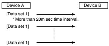
flowchart
graph LR
    A["Device A"] --> B["Device B"]
    C["[Data set 1"]] --> D["* More than 20m sec time interval."]
    E["[Data set 1"]] --> F["..."]
    G["[Data set 1"]] --> H["..."]
•Device B requesting data from Device A
Device B sends an RQ1 message to Device A.
Checking the message, Device A sends a DT1 message back to Device B.
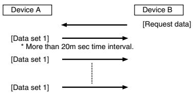
flowchart
graph LR
    A["Device A"] <--> B["Device B"]
    C["[Data set 1"] * More than 20m sec time interval.] --> D["[Data set 1"]]
    D --> E["[Data set 1"]]
    E --> F["[Request data"]]
MIDI Implementation
Model: GI-20
Date: Dec. 28, 2002
Version: 1.00
1. USB
When MIDI PLAYBACK is OFF, identical messages are transmitted from USB and MIDI. When MIDI PLAYBACK is ON, messages transmitted from the computer to the GI-20's USB are sent through to MIDI OUT. Refer to "Signal Flow" (p. 8).
2. Receive Data (MIDI IN)
■Channel Voice Messages
Can be received only through the Control Channel.
However, these are received through all channels when the Control Channel is set to Omni On.
●Control Change
Control Changes (1–95) other than those for Bank Select, Data Entry, and general purpose controllers 3–8 are transmitted with their channels converted as follows:
In MONO mode: changed to the six channels starting with the basic channel In POLY mode: changed to the basic channel only
For more on the functions of each Control Change, refer to the data sheet for the sound module being used.
General purpose controllers 3–8 are imported to the GI-20 and controls assigned function of on-board controllers.
○General Purpose Controller 3
| Status | 2nd byte | 3rd byte |
| BnH | 12H | vvH |
| n=MIDI channel number: | 0H - FH (0 - 15) 0=ch.1 15=ch.16 |
| vv= Control value: | 00H - 7FH (0-127) |
* Can be received only through the Control Channel.
* Recognized as control data for the expression pedal connected to the GI-20.
* Does not convert to basic channel for transmission.
○General Purpose Controller 4
| Status | 2nd byte | 3rd byte |
| BnH | 13H | vvH |
| n=MIDI channel number: | 0H - FH (0 - 15) | 0=ch.1 15=ch.16 |
| vv= Control value: | 00H - 7FH (0-127) | 00H-3FH=OFF, 40H-7FH=ON |
* Can be received only through the Control Channel.
* Recognized as control data for the Soft Switch 1 connected to the GI-20.
* Does not convert to basic channel for transmission.
○General Purpose Controller 5
| Status | 2nd byte | 3rd byte |
| BnH | 50H | vvH |
| n=MIDI channel number: | 0H - FH (0 - 15) 0=ch.1 15=ch.16 |
| vv= Control value: | 00H - 7FH (0 - 127) 00H - 3FH=OFF, 40H-7FH=ON |
* Can be received only through the Control Channel.
* Recognized as control data for the Soft Switch 2 connected to the GI-20.
* Does not convert to basic channel for transmission.
○General Purpose Controller 6
| Status | 2nd byte | 3rd byte |
| BnH | 51H | vvH |
| n=MIDI channel number: | 0H - FH (0 - 15) 0=ch.1 15=ch.16 |
| vv= Control value: | 00H - 7FH (0 - 127) |
* Can be received only through the Control Channel.
* Recognized as GK Volume control data.
* Does not convert to basic channel for transmission.
○General Purpose Controller 7
| Status | 2nd byte | 3rd byte |
| BnH | 52H | vvH |
| n=MIDI channel number: | 0H - FH (0 - 15) 0=ch.1 15=ch.16 |
| vv= Control value: | 00H - 7FH (0 - 127) 00H-3FH=OFF,40H-7FH=ON |
* Can be received only through the Control Channel.
* Recognized as S1 Switch 1 control data.
* Does not convert to basic channel for transmission.
○General Purpose Controller 8
| Status | 2nd byte | 3rd byte |
| BnH | 53H | vvH |
| n=MIDI channel number: | 0H - FH (0 - 15) 0=ch.1 15=ch.16 |
| vv= Control value: | 00H - 7FH (0 - 127) 00H-3FH=OFF, 40H - 7FH=ON |
* Can be received only through the Control Channel.
* Recognized as S2 Switch 1 control data.
* Does not convert to basic channel for transmission.
●Program Change
| Status | 2nd byte |
| CnH | ppH |
| n=MIDI channel number: | 0H - FH (0 - 15) 0=ch.1 15=ch.16 |
| pp= Program number : | 00H - 31H (0 - 49) |
* Can be received only through the Control Channel.
* The patch corresponding to the Program number that's been received is called up.
■System Exclusive Message
| Status | data byte | Status |
| F0H | iiH,ddH,......,eeH | F7H |
| F0H: | System Exclusive |
| ii=ID number: | 41H (65) |
| dd,...,ee= Data: | 00H-7FH (0-127) |
| F7H: | EOX (End of Exclusive/System common) |
* For more details, refer to the page "Roland exclusive message" and Section 4 or after.
3. Transmit Data
The following are messages transmitted from the USB and MIDI connectors (when MIDI PLAYBACK is OFF).
When MIDI PLAYBACK is OFF, identical messages are transmitted by USB and MIDI.
When MIDI PLAYBACK is ON, messages transmitted from the computer to the GI-20's USB are sent through to MIDI OUT.
Refer to "Signal Flow" (p. 8).
■Channel Voice Messages
○Note Off
| Status | 2nd byte | 3rd byte |
| 9nH | kkH | 00H |
| n=MIDI channel number: | 0H - FH (0 - 15) 0=ch.1 15=ch.16 | |
| kk= Note number: | 00H - 7FH (0 - 127) | |
○Note On
| Status | 2nd byte | 3rd byte |
| 9nH | kkH | vvH |
| n=MIDI channel number: | 0H - FH (0 - 15) 0=ch.1 15=ch.16 | |
| kk= Note number : | 00H - 7FH (0 - 127) | |
| vv= Velocity: | 01H - 7FH (1 - 127) | |
●Control Change
Control Changes (1–95) other than those for Bank Select, Data Entry, and general purpose controllers 3–8 received through the control channel, the channels are converted and messages are transmitted as shown below.
Control Changes assigned to the expression pedal, foot switch, and GK Volume are also transmitted over the channels shown below.
In MONO mode: the six channels starting with the basic channel In POLY mode: only the basic channel
○Bank Select
| Status | 2nd byte | 3rd byte |
| BnH | 00H | mmH |
| BnH | 20H | llH |
n=MIDI channel number: 0H - FH (0 - 15) 0=ch.1 15=ch.16 mm,ll= Bank number: 00 00H - 7F 7FH (bank 1 - bank 16384)
* Transmitted when the power to the GI-20 is turned on, when editing Bank Select, and when patches are switched.
* Not transmitted when the patch parameter's Bank Select Switch is set to OFF or when the system parameter PC MASK is set to ON.
○Data Entry
| Status | 2nd byte | 3rd byte |
| BnH | 06H | mmH |
| BnH | 26H | llH |
n=MIDI channel number: 0H - FH (0 - 15) 0=ch.1 15=ch.16 mm,ll=the value of the parameter specified by RPN
ORPN MSB/LSB
Control change includes RPN (registered parameter number), function which are defined by the MIDI standard. The GI-20 can transmit only RPN: pitch bend sensitivity (RPN#0) and channel fine tuning (RPN#1).
| RPN | Data entry | |
| MSB LSB | MSB LSB | Notes |
| 00H 00H | mmH 00H | Pitch Bend Sensitivitymm:00H - 18H (0 - 24 semitone)LSB always transmits 00H.* Transmitted when the power to the GI-20 is turned on, when the BEND RANGE parameters are edited, and when patch changes are transmitted. |
| 00H 01H | mmH llH | Channel Fine Tuningmm,ll: 20 00H - 40 00H - 60 00H(-4096 x 100 / 8192 - 0 - +4096 x 100 / 8192 cent)* Transmitted when the power to the GI-20 is turned on, when the basic pitch is edited, and when patch changes are transmitted. |
●Program Change
| Status | 2nd byte | |
| CnH | ppH | |
| n=MIDI channel number: | 0H - FH (0 - 15) 0=ch.1 15=ch.16 | |
| pp= Program number: | 00H - 7FH (0 - 127) 0=prg.1 127=prg.128 | |
* Transmitted when the power to the GI-20 is turned on, when Program Changes are edited, and when patch changes are transmitted.
* Not transmitted when the patch parameter's Program Change Switch is set to OFF or when the system parameter PC MASK is set to ON.
●Pitch Bend Change
| Status | 2nd byte | 3rd byte |
| EnH | llH | mmH |
| n= MIDI channel number: | 0H - FH (0 - 15) 0=ch.1 15=ch.16 | |
| mm,ll= Value: | 00H, 00H - 7FH, 7FH (-8192 - +8191) | |
■Channel Mode Message
- Reset All Controller
| Status | 2nd bye | 3rd byte |
| BnH | 79H | 00H |
n = MIDI Channel number: 0H - FH (0 - 15) 0=ch.1 15=ch.16
* Transmitted when the MIDI PLAYBACK is switched, when the Bulk mode is selected, and when the parameter is edited.
■System Realtime Message
●Active Sensing
Status
FEH
* This message is always transmitted at about 250 msec intervals.
■System Exclusive Message
| Status | Data byte | Status |
| F0H | iiH,ddH,......,eeH | F7H |
F0H: System Exclusive
ii=ID number: 41H (65)
dd,...,ee=Data: 00H-7FH (0-127)
F7H: EOX (End of Exclusive/System common)
* For more details, refer to the page "Roland exclusive message" and Section 4 or after.
4. Exclusive Communications
The GI-20 is capable of transmitting and receiving system parameters and patch parameters using certain exclusive messages. The model ID is 00H 6AH. The Device ID is fixed as 10H. The use of Device ID 7FH (Broadcast) is not supported.
●Data Set 1 DT1 (12H)
| Byte | Explanation |
| F0H | Exclusive Status |
| 41H | Manufacturer ID (Roland) |
| 10H | Device ID (Dev=10H) |
| 00H | Model ID MSB (GI-20) |
| 6AH | Model ID LSB (GI-20) |
| 12H | Command ID (DT1) |
| aaH | Address MSB |
| bbH | Address |
| ccH | Address |
| ddH | Address LSB |
| eeH | Data |
| : | : |
| ffH | Data |
| sum | Checksum |
| F7H | EOX (End of Exclusive) |
* The GI-20 can only transmit and receive bulk data, not individual data.
* Data is received only when the unit has been placed in standby, in the Bulk Load screen.
* The use of Data Request is not supported.
* Data is transmitted when [WRITE] is pressed in the Bulk Load screen.
* Does not respond to Identity Request inquiry messages.
Decimal and Hexadecimal table
With a MIDI System, the data value, the address, or size in an exclusive message is expressed in 7-bit hexadecimal values. The table below shows decimal value and their hexadecimal counterparts.
| 10 | 16 | 10 | 16 | 10 | 16 | 10 | 16 |
| 0 | 00H | 32 | 20H | 64 | 40H | 96 | 60H |
| 1 | 01H | 33 | 21H | 65 | 41H | 97 | 61H |
| 2 | 02H | 34 | 22H | 66 | 42H | 98 | 62H |
| 3 | 03H | 35 | 23H | 67 | 43H | 99 | 63H |
| 4 | 04H | 36 | 24H | 68 | 44H | 100 | 64H |
| 5 | 05H | 37 | 25H | 69 | 45H | 101 | 65H |
| 6 | 06H | 38 | 26H | 70 | 46H | 102 | 66H |
| 7 | 07H | 39 | 27H | 71 | 47H | 103 | 67H |
| 8 | 08H | 40 | 28H | 72 | 48H | 104 | 68H |
| 9 | 09H | 41 | 29H | 73 | 49H | 105 | 69H |
| 10 | 0AH | 42 | 2AH | 74 | 4AH | 106 | 6AH |
| 11 | 0BH | 43 | 2BH | 75 | 4BH | 107 | 6BH |
| 12 | 0CH | 44 | 2CH | 76 | 4CH | 108 | 6CH |
| 13 | 0DH | 45 | 2DH | 77 | 4DH | 109 | 6DH |
| 14 | 0EH | 46 | 2EH | 78 | 4EH | 110 | 6EH |
| 15 | 0FH | 47 | 2FH | 79 | 4FH | 111 | 6FH |
| 16 | 10H | 48 | 30H | 80 | 50H | 112 | 70H |
| 17 | 11H | 49 | 31H | 81 | 51H | 113 | 71H |
| 18 | 12H | 50 | 32H | 82 | 52H | 114 | 72H |
| 19 | 13H | 51 | 33H | 83 | 53H | 115 | 73H |
| 20 | 14H | 52 | 34H | 84 | 54H | 116 | 74H |
| 21 | 15H | 53 | 35H | 85 | 55H | 117 | 75H |
| 22 | 16H | 54 | 36H | 86 | 56H | 118 | 76H |
| 23 | 17H | 55 | 37H | 87 | 57H | 119 | 77H |
| 24 | 18H | 56 | 38H | 88 | 58H | 120 | 78H |
| 25 | 19H | 57 | 39H | 89 | 59H | 121 | 79H |
| 26 | 1AH | 58 | 3AH | 90 | 5AH | 122 | 7AH |
| 27 | 1BH | 59 | 3BH | 91 | 5BH | 123 | 7BH |
| 28 | 1CH | 60 | 3CH | 92 | 5CH | 124 | 7CH |
| 29 | 1DH | 61 | 3DH | 93 | 5DH | 125 | 7DH |
| 30 | 1EH | 62 | 3EH | 94 | 5EH | 126 | 7EH |
| 31 | 1FH | 63 | 3FH | 95 | 5FH | 127 | 7FH |
* When expressing a MIDI channel number or a program change number, please notice that the values are less by one. For example, MIDI channel is expressed as 0 through 15 instead of 1 through 16.
* The range of 7 bit can express 128 steps from 0 to 127. To express broader range, use several data bytes.
GK-MIDI INTERFACE
Model GI-20
MIDI Implementation Chart
Date: Dec. 26, 2002
Version: 1.00
| Function... | Transmitted | Recognized | Remarks | |
| Basic Channel | Default Changed | 1-16 1-16 | 1-16 1-16 | * 1 * 1 |
| Mode | Default Messages Altered | Mode 3, 4 (M=6) X********** | Mode 1, 3 X | * 1 |
| Note Number : | True Voice | 0-127********** | X********** | |
| Velocity | Note ON Note OFF | O 9n V=1-127 X 9n V=0 | X X | |
| After Touch | Key's Ch's | X X | X X | |
| Pitch Bend | O | X | ||
| Control Change | 0, 32 6-38 18 19 80 81 82 83 1-31, 64-95 33-63 98, 99 others | O O O O O O O O O O O O O O O O O O O O O O O O O O O O O O O O O O O O O O O O O O O O O O O O O O O O O O O O O O O O O O O O O O O O O O O O O O O O O O O O O O O O O O O O O O O O O O O O O O O O O | X X O * 2 O * 2 O * 2 O * 2 O * 2 O * 2 O * 2 O * 2 O * 2 O * 2 O * 2 O * 2 O * 2 O * 2 O * 2 O * 2 O * 2 O * 2 O * 2 O * 2 O * 2 O * 2 O * 2 O * 2 O * 2 O * 4 | Bank Select Data Entry General Purpose Controller 3 (Expression Pedal) General Purpose Controller 4 (Foot Switch 1) General Purpose Controller 5 (Foot Switch 2) General Purpose Controller 6 (GK Volume) General Purpose Controller 7 (S1 Switch) General Purpose Controller 8 (S2 Switch) NRPN LSB, MSB RPN LSB, MSB |
| Prog Change : True # | O********** | O * 2 0-49 | ||
| System Exclusive | O | O * 4 | ||
| System Common : Song Pos : Song Sel : Tune | X X X | X X X | ||
| System Real Time : Command | X X | X X | ||
| Aux Message : All sound off : Reset All Controller : Local ON/OFF : All Notes OFF : Active Sense : Reset | X O X X O X | X X X X X | ||
| Notes | * 1 Can be memorized after powering off. * 2 O X is selectable. * 3 Can be assigned the Expression Pedal, Foot Switch 1/2, and GK Volume. * 4 Can be received when Bulk Load is standby. * The above messages are transmitted from USB and MIDI (when MIDI PLAYBACK is OFF). * When MIDI PLAYBACK is OFF, identical messages are transmitted from USB and MIDI. * When MIDI PLAYBACK is ON, messages transmitted from the computer to the GI-20's USB are sent through to MIDI OUT. | |||
Mode 1 : OMNI ON, POLY
Mode 2 : OMNI ON, MONO
O: Yes
Mode 3 : OMNI OFF, POLY
Mode 4 : OMNI OFF, MONO
X : No
Specifications
GI-20: GK-MIDI Interface
- Patches
50
- Display
2 characters, 7 segment LED
Connectors
GK IN
FOOT SW
EXP PDL
GUITAR OUT
MIDI IN
MIDI OUT
USB
DC IN
● Power Supply
DC 9 V; Supply AC adaptor (BOSS PSA-S series, Roland ACI or ACB series)
● Current Draw
450 mA
- Dimensions
8-5/8 (W) x 9-3/8 (D) x 1-3/4 (H) inches
(including rubber foot)
8-5/8 (W) x 9-3/8 (D) x 1-7/8 (H) inches
- Weight
1.3 kg/2 lbs 14 oz (excluding AC adaptor)
- Accessories
AC Adaptor (BOSS PSA-S series, Roland ACI or ACB series)
GK Cable (3 m)
MIDI Cable (1 m)
Owner's Manual
CD-ROM (USB driver)
Rubber Foot x 4
- Options
Divided Pickup: GK-3/GK-2A (for guitar), GK-3B/GK-2B (for bass)
GK Cable: GKC-3 (3 m), GKC-5 (5 m), GKC-10 (10 m)
Foot Switch: FS-5U (BOSS)
Dual Foot Switch: FS-6 (BOSS)
Connection Cord: PCS-31
Expression Pedal: EV-5
Rackmount Adaptor: RAD-50
MIDI Foot Controller: FC-300, GFC-50
Unit Selector: US-20

In the interest of product improvement, the specifications and/or appearance of this unit are subject to change without prior notice.
Installing & Setup the Driver
In order to use the GI-20 USB, you must first install the USB MIDI driver. The USB MIDI Driver is included in the “GI-20 Driver CD-ROM.”
■ What is USB MIDI Driver?
The GI-20 Driver is software which passes data between the GI-20 and the application (sequencer software etc.) that is running on the USB-connected computer.
The GI-20 Driver sends data from the application to the GI-20, and passes data from the GI-20 to the application.
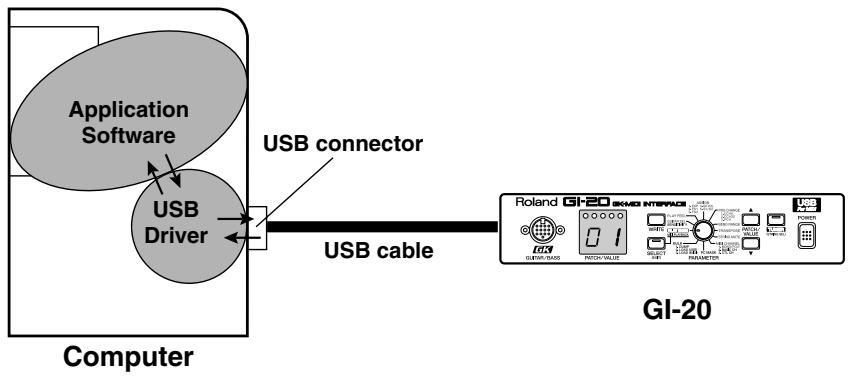
flowchart
graph LR
    A["Application Software"] --> B["USB Driver"]
    B --> C["USB connector"]
    C --> D["USB cable"]
    D --> E["GLI-20 Interface"]
    style A fill:#f9f,stroke:#333
    style B fill:#ccf,stroke:#333
    style C fill:#cfc,stroke:#333
    style D fill:#fcc,stroke:#333
    style E fill:#cff,stroke:#333
The explanation about installing and setup the driver is organized according to the computer and USB MIDI driver that you are using. Please proceed to the following pages.
Installing & Setting Up the Driver (Windows) ...... (p. 46)
Installing & Setting Up the Driver (Macintosh) ...... (p. 59)
Installing & Setting Up the Driver (Windows)
Driver Installation
The installation procedure will differ depending on your system.
Please proceed to one of the following sections, depending on the system you use.
- Windows XP users ...... (p. 46)
- Windows 2000 users...... (p. 51)
- Windows Me/98 users ...... (p. 55)
Windows XP users
- With the GI-20 disconnected, start up Windows.
Disconnect all USB cables except for a USB keyboard and USB mouse (if used).
- Open the "System Properties" dialog box.
1) Click the Windows "Start" menu, and from the menu, select "Control Panel."
2) In "Pick a category", click "Performance and Maintenance".
3) In "or pick a Control Panel icon", click the "System" icon.
- Click the [Hardware] tab, and then click [Driver Signing].
Open the Driver Signing Options dialog box.
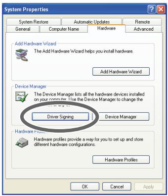
- Make sure that "What action do you want Windows to take?" is set to [Ignore].
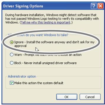
If it is set to "Ignore", simply click [OK]. If it is not set to "Ignore", make a note of the current setting ("Warn" or "Block"). Then change the setting to "Ignore" and click [OK].
NOTE
If you are using Windows XP Professional, you must log on using a user name with an administrative account type (e.g., Administrator). For details on user accounts, please consult the system administrator of your computer.
MEMO
Depending on how your system is set up, the System icon may be displayed directly in the Control Panel (the Classic display). In this case, double-click the System icon.
MEMO
If you changed "What action do you want Windows to take?" in step 4, you must restore the previous setting after you have installed the driver.
→ If you changed "What action do you want Windows to take?" (p. 50)
- Click [OK] to close the "System Properties" dialog box.
- Exit all currently running software (applications).
Also close any open windows. If you are using virus checking or similar software, be sure to exit it as well.
- Prepare the CD-ROM.
Insert the CD-ROM into the CD-ROM drive of your computer.
- Click the Windows "start" button. From the menu that appears, select "Run...".
Open the "Run..." dialog box.
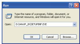
- In the dialog box that appears, input the following into the "Open" field, and click [OK].
D:\WinXP_2K\SETUPINF.EXE
* The drive name "D:" may be different for your system. Specify the drive name of your CD-ROM drive.
The SetupInf dialog box will appear.
You are now ready to install the driver.
![SetupInf Ready to install the driver. 1. Please use a USB cable to connect the OI-20 and your computer, and then turn on the power of the OI-20. 2. The "Found New Hardware Wizard" dialog box will appear, so select "Install from a list or specific location," and then click the [Next] button. 3. Select "Don't search. I will choose the driver to install," and then click the [Next] button. 4. Make sure that "Roland OI-20" is selected in the Models field, and click the [Next] button. 5. If the "Insert Disk" dialog box appears at this time, click the [OK] button. 6. The "Files Needed" dialog box will appear, so input the name of the folder containing the driver D:\Win\OP_2K into the "Copy files from" area, and perform the installation. 7. After inputting the folder name, click the [OK] button in the dialog box. The setup program will finish. OK](/content/2025/01/130723/images/e7b28f13f1dbb54f02516bd2d9cc56bc62316af7c3ff5083cae80f292b4cd14b.jpg)
- Connect the GI-20 to your computer.
1) With the power switch turned OFF, connect the AC adaptor to the GI-20.
2) Connect the AC adaptor to an electrical outlet.
3) Use the USB cable to connect the GI-20 to your computer.
USB connector of your Computer
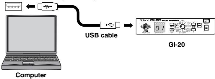
flowchart
graph LR
    A["Computer"] -->|USB cable| B["G-20 Bluetooth"]
    B --> C["Handheld device with I/O ports and display screen"]
- Switch ON the GI-20's power switch.
Near the task bar, your computer will indicate "Found New Hardware". Please wait.
MEMO
In this manual, the location of folders and files is given in terms of the file path, using \ as the delimiter. For example, WinXP_2K\SETUPINF.EXE indicates the SETUPINF.EXE file found in the WinXP_2K folder.

Once the connections have been completed, turn on power to your various devices in the order specified. By turning on devices in the wrong order, you risk causing malfunction and/or damage to other devices.
MEMO
This unit is equipped with a protection circuit. A brief interval (a few seconds) after power up is required before the unit will operate normally.
Installing & Setting Up the Driver (Windows)
The Found "New Hardware Wizard" will appear.
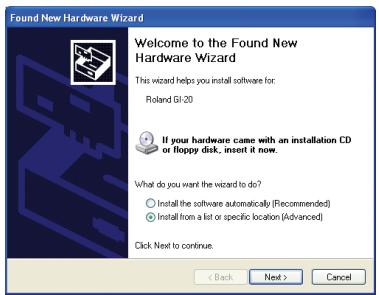
- Make sure that the screen indicates "Roland GI-20", select "Install from a list or specific location (Advanced)", and click [Next].
The screen will indicate "Please choose your search and installation options".
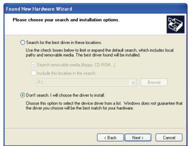
- Select "Don't search. I will choose the driver to install", and click [Next].
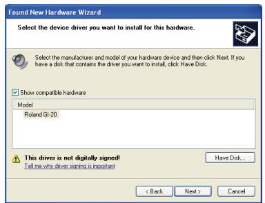
- Make sure that the "Model" field indicates "Roland GI-20", and click [Next].
Driver installation will begin.
If the "What action do you want Windows to take?" setting was not set to "Ignore", a "Hardware Installation" dialog box will appear.
If “What action do you want Windows to take?” is set to “Warn,”
Open the “!” mark dialog box.
- Click [Continue Anyway].
- Continue the installation.
If “What action do you want Windows to take?” is set to “Block”
Open the "X" mark dialog box.
- Click [OK].
- When the "Found New Hardware Wizard" appears, click [Finish].
- Quit Windows, turn off the power to all devices, then begin the procedure again starting from Step 1 (p. 46).
The Insert Disk dialog box will appear.
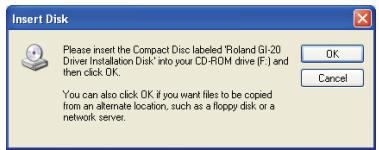
15. Click [OK].
The "Files Needed" dialog box will appear.
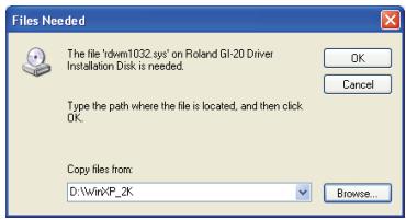
16. Input the following into the "Copy files from" field, and click [OK].
D:\WinXP_2K
* The drive name "D:" may be different for your system. Specify the drive name of your CD-ROM drive.
The "Found New Hardware Wizard" will appear.
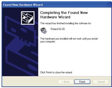
17. Make sure that the display indicates "Roland GI-20", and click [Finish].
Wait until "Found New Hardware" appears near the taskbar.
When driver installation has been completed, the System Setting Change dialog box will appear.
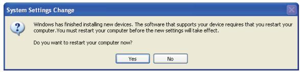
18. Click [Yes].
Windows will restart automatically.
MEMO
The Insert Disk dialog may not appear. In that case, proceed to step 17.
If you changed "What action do you want Windows to take?"
If you changed the What action do you want Windows to take? setting, restore the original setting after Windows restarts.
- If you are using Windows XP Professional, log on to Windows using the user name of an administrative account (e.g., Administrator).
- Click the Windows "start" menu, and from the menu, select "Control Panel".
- In "Pick a category", click "Performance and Maintenance".
- In "or pick a Control Panel icon", click the System icon.
The System Properties dialog box will appear.
* Depending on how your system is set up, the System icon may be displayed directly in the Control Panel (the Classic display). In this case, double-click the System icon. - Click the [Hardware] tab, and then click [Driver Signing]. The Driver Signing Options dialog box will appear.
- Return the "What action do you want Windows to take? setting to the original setting (either "Warn" or "Block"), and click [OK].
- Click [OK].
The System properties dialog box will close.
Next, you need to make the driver settings. (p. 57)
■ Windows 2000 users
- With the GI-20 disconnected, start up Windows.
Disconnect all USB cables except for a USB keyboard and USB mouse (if used).
- Log on to Windows as a user with administrative privileges (such as Administrator).
- Open the "System Properties" dialog box.
1) Click the Windows Start button, and from the menu that appears, select "Settings | Control Panel."
2) In Control Panel, double-click the System icon.
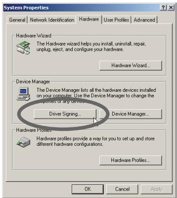
- Click the [Hardware] tab, and then click [Driver Signing].
Open the Driver Signing Options dialog box.
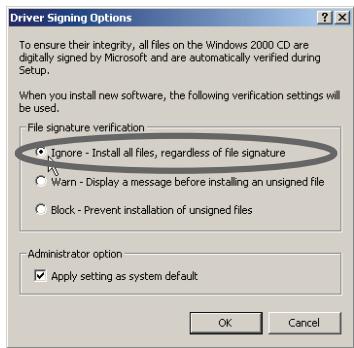
- Make sure that "File signature verification" is set to "Ignore".
If it is set to "Ignore", simply click [OK]. If it is not set to "Ignore", make a note of the current setting ("Warn" or "Block"). Then change the setting to "Ignore" and click [OK].
-
Click [OK] to close the "System Properties" dialog box.
-
Exit all currently running software (applications).
Also close any open windows. If you are using virus checking or similar software, be sure to exit it as well.
- Prepare the CD-ROM.
Insert the CD-ROM into the CD-ROM drive of your computer.
- Click the Windows Start button. From the menu that appears, select "Run...".
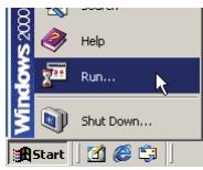
MEMO
If you changed the "File signature verification" setting in step 5, you must restore the previous setting after you have installed the driver.
→ If you changed "File signature verification" (p. 54)
Installing & Setting Up the Driver (Windows)
Open the "Run..." dialog box.
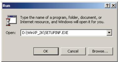
10. In the dialog box that appears, input the following into the "Open" field, and click [OK].
* The drive name "D:" may be different for your system. Specify the drive name of your CD-ROM drive.
The "SetupInf" dialog box will appear.
You are now ready to install the driver.
![SetupInf Ready to install the driver. Please use a USB cable to connect the GI-20 and your computer, and then turn on the power of the GI-20. The "Insert Disk" dialog box will appear. Click the [OK] button. The "Files Needed" dialog box will appear, so input the name of the folder containing the driver D:\Win\IP_2K into the "Copy files from" area, and perform the installation. After inputting the folder name, click the [OK] button in the dialog box. The setup program will finish. OK](/content/2025/01/130723/images/aaf21a19a1400970e4bb1fde104ba4b48a869e6cfbe019f16f13438af6c11852.jpg)
11. Connect the GI-20 to your computer.
1) With the power switch turned OFF, connect the AC adaptor to the GI-20.
2) Connect the AC adaptor to an electrical outlet.
3) Use the USB cable to connect the GI-20 to your computer.
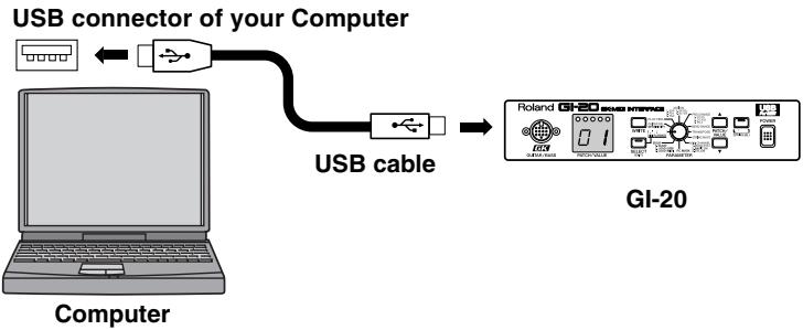
flowchart
graph TD
    A["Computer"] -->|USB connector of your Computer| B["USB cable"]
    B --> C["GI-20"]
12. Switch ON the GI-20's power switch.

Once the connections have been completed, turn on power to your various devices in the order specified. By turning on devices in the wrong order, you risk causing malfunction and/or damage to other devices.
MEMO
This unit is equipped with a protection circuit. A brief interval (a few seconds) after power up is required before the unit will operate normally.
If the “File signature verification” setting was not set to “Ignore”, a “Digital Signature Not Found” dialog box will appear.
If “File signature verification” is set to “Warn,”
- Click [Yes].
- Continue the installation.
If “File signature verification” is set to “Block”
- Click [OK].
- When the "Found New Hardware Wizard" appears, click [Finish].
- Quit Windows, turn off the power to all devices, then begin the procedure again starting from Step 1 (p. 51).
The Insert Disk dialog box will appear.
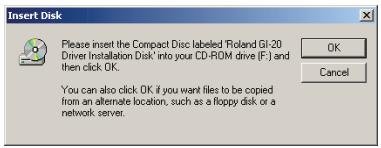
13. Click [OK].
The "Files Needed" dialog box will appear.
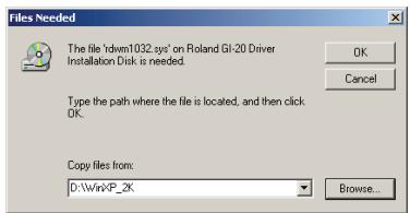
14. Input the following into the "Copy files from" field, and click [OK].
D:\WinXP_2K
* The drive name "D:" may be different for your system. Specify the drive name of your CD-ROM drive.
* The "Found New Hardware Wizard" may be displayed. Verify that "Roland GI-20" is displayed, and click [Finish].
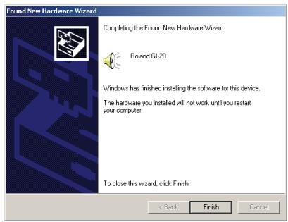
NOTE
If the Insert Disk dialog box does not appear, please read The "Insert Disk" dialog box does not appear (p. 65).
Installing & Setting Up the Driver (Windows)
* The System Settings Change dialog box may appear. Click [Yes]. Windows will restart automatically.
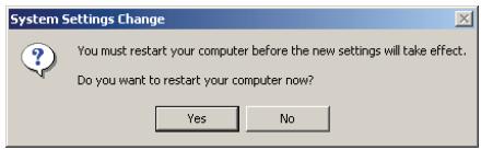
15. Restart Windows.
If you changed "File signature verification"
If you changed the "File signature verification" setting, restore the original setting after Windows restarts.
- After Windows restarts, log in to Windows as a user with administrative privileges, (such as Administrator).
- In the Windows desktop, right-click the "My Computer" icon, and from the menu that appears, select "Properties."
The System Properties dialog box will appear. - Click the [Hardware] tab, and then click [Driver signature].
The Driver Signing Options dialog box will appear. - Return the "File signature verification" setting to the original setting (either [Warn] or [Block]), and click [OK].
- Click [OK].
The System properties dialog box will close.
Next, you need to make the driver settings. (p. 57)
■ Windows Me/98 users
- With the GI-20 disconnected, start up Windows.
Disconnect all USB cables except for a USB keyboard and USB mouse (if used).
- Exit all currently running software (applications).
Also close any open windows. If you are using virus checking or similar software, be sure to exit it as well.
- Prepare the CD-ROM.
Insert the CD-ROM into the CD-ROM drive of your computer.
- Click the Windows Start button. From the menu that appears, select "Run...".
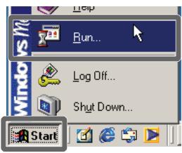
Open the "Run..." dialog box.
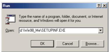
- In the dialog box that appears, input the following into the "Open" field, and click [OK].
D:\Win98_Me\Setupinf.exe
* The drive name "D:" may be different for your system. Specify the drive name of your CD-ROM drive.
The SetupInf dialog box will appear.
You are now ready to install the driver.
![Ready to install the driver. Please use a USB cable to connect the OI-20 and your computer, and then turn on the power of the OI-20. * If the "Insert Disk" dialog box appears after turning on the power, click the [OK] button. The "New Hardware Found" dialog box will appear, so input the name of the folder containing the driver D:\WIN98_ME into the "Copy files from" area, and perform the installation. After inputting the folder name, click the [OK] button in the dialog box. The setup program will finish.](/content/2025/01/130723/images/85e6d97e77a1b01b46ceec23db89191c0eeea9c657c1a1c4c9ff82595d270d12.jpg)
MEMO
In this manual, the location of folders and files is given in terms of the file path, using \ as the delimiter. For example, Win98_Me\SETUPINF.EXE indicates the SETUPINF.EXE file found in the Win98Me folder.
Installing & Setting Up the Driver (Windows)
6. Connect the GI-20 to your computer.
1) With the power switch turned OFF, connect the AC adaptor to the GI-20.
2) Connect the AC adaptor to an electrical outlet.
3) Use the USB cable to connect the GI-20 to your computer.
USB connector of your Computer
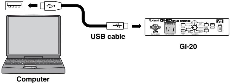
flowchart
graph LR
    A["Computer"] -->|USB cable| B["Hand"]
    B --> C["GL-20 Interface"]
7. Switch ON the GI-20's power switch.
* If you are using Windows 98, an Insert Disk dialog box will appear. Click [OK].
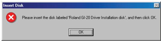
The "New Hardware Found" dialog box will appear.
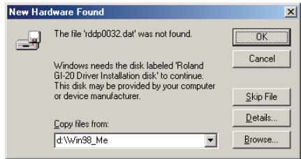
8. Input the following into the "Copy files from" field, and click [OK].
D:\Win98_Me
* The drive name "D:" may be different for your system. Specify the drive name of your CD-ROM drive.
Once the driver has been installed, New Hardware Found dialog box will close.
9. In the SetupInf dialog box, click [OK].
The SETUPINF dialog box will close.
Next, you need to make the driver settings. (p. 57)
![ROLAND GI-20 - In the SetupInf dialog box, click [OK]. - 1](/content/2025/01/130723/images/4a82d1331a6d00b244bdffa0a9a13f2fc3069dd5a0fc9d813b520c1027f6625e.jpg)
Once the connections have been completed, turn on power to your various devices in the order specified. By turning on devices in the wrong order, you risk causing malfunction and/or damage to other devices.
MEMO
This unit is equipped with a protection circuit. A brief interval (a few seconds) after power up is required before the unit will operate normally.
NOTE
If you are using Windows 98 and the Insert Disk dialog box dose not appear, please read The "Insert Disk" dialog box does not appear (p. 65).
Settings
■ MIDI input and output destinations
Windows XP/2000/Me users
1. Open "Control Panel."
Click the Windows Start button, and from the menu that appears, select "Settings | Control Panel."
Windows XP
Click the Windows start button, and from the menu that appears, select "Control Panel."
2. Open the "Sounds and Audio Devices Properties" dialog box (or in Windows 2000/Me, Sounds and Multimedia Properties).
Windows XP
1) In "Pick a category", click "Sound, Speech, and Audio Devices".
2) Next, in "or pick a Control Panel icon", click the "sounds and Audio Devices" icon.
1) In Control Panel, double-click the "Sounds and Multimedia" icon to open the "Sounds and Multimedia Properties" dialog box.
Windows 2000/Me
3. Click the Audio tab.
4. For MIDI music playback, click the ▼ located at the right of [Default device] (or in Windows 2000/Me, [Preferred device]), and select the following from the list that appears.
Roland GI-20 MIDI OUT
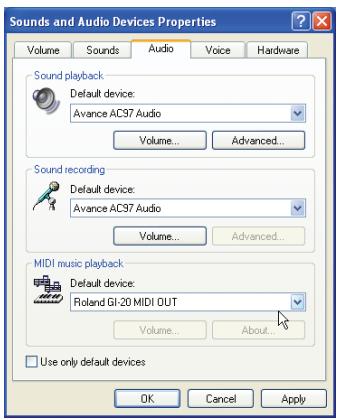
5. Click [OK] to close the "Sounds and Audio Devices Properties" dialog box.
This completes driver settings.
MEMO
Depending on how your system is set up, the “Sounds and Audio Devices” icon may be displayed directly in the Control Panel (the Classic display). In this case, double-click the “Sounds and Audio Devices” icon.
MEMO
If the "Sound and Multimedia" icon is not displayed, click "Show all control panel options" in the frame at the left.
Installing & Setting Up the Driver (Windows)
Windows 98 users
- Open "Control Panel."
Click the Windows Start button, and from the menu that appears, select "Settings | Control Panel." - Open the "Multimedia Properties" dialog box.
In Control Panel, double-click the Multimedia icon to open the “Multimedia Properties” dialog box. - Click the MIDI tab.
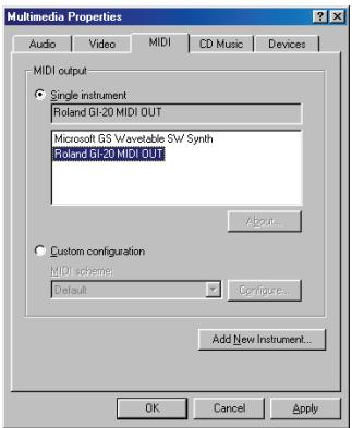
- Set "MIDI output".
Select [Single instrument], and choose one of the following from the list that appears.
Roland GI-20 MIDI OUT
- Click [OK] to close the "Multimedia Properties" dialog box.
This completes driver settings.
Installing & Setting Up the Driver (Macintosh)
■ System requirements This driver has the following requirements.
Operating System:
Mac OS 8.5, 8.6, or 9.x
Computer:
Apple USB Ready Macintosh
* This driver has been shown to function properly when used with average computer systems having specifications that conform to the above guidelines. You should be aware, however, that there are numerous other variables that can affect performance, including differences in hardware design, system configuration, and overall combination of software applications that are used. Therefore, the actual system requirements could be different than the above.
Installing the driver
Use either OMS or FreeMIDI as the MIDI driver.
The included GI-20 driver is an add-on module for using the GI-20 with OMS or FreeMIDI.
* Either OMS or FreeMIDI must be installed in your Macintosh, as appropriate for the sequencer software you are using.
Use the following procedure to install the GI-20 driver.
Disconnect the GI-20 from the Macintosh before you perform the installation.
If the power of the GI-20 is turned on, a message like the following will appear when the Macintosh is started up. Perform the steps described below as appropriate for the message that is displayed.
If the screen indicates:
"Driver required for USB device `unknown device' is not available. Search for driver on the Internet?"
→ click [Cancel].
If the screen indicates:
"Software required for using device `unknown device' cannot be found. Please refer to the manual included with the device, and install the necessary software."
→ click [OK].
- Exit all currently running software (applications).
If you are using a virus checker or similar software, be sure to exit this as well.
- Prepare the CD-ROM.
Insert the CD-ROM into the CD-ROM drive.
- Double-click the GI-20 Driver-E Installer icon (found in the GI-20 Driver E folder of the CD-ROM) to start up the installer.

GI-20 Driver-E Installer
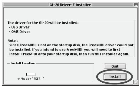
MEMO
OMS can be found in the OMS 2.3.8 E folder of the CD-ROM. If you would like to learn more about OMS, refer to OMS_2.3_Mac.pdf in the OMS 2.3.8E folder of the CD-ROM. In order to read "OMS_2.3_Mac.pdf," you will need the Adobe Acrobat Reader.

The indication for the "Install Location" will differ depending on your system. Make sure that the startup disk for the system you are using is selected.
Installing & Setting Up the Driver (Macintosh)
4. Verify the Install Location, and click [Install].
* If a message like the following is displayed, click [Continue]. The other currently running applications will exit, and installation will continue.
![ROLAND GI-20 - Verify the Install Location, and click [Install]. - 1](/content/2025/01/130723/images/c73465d0953ff46100419e57400ba44383d1dd2faae1a75b78d48a2d3176bc04.jpg)
This installation requires your computer to restart after installing this software. Click Continue to automatically quit all other running applications. Click Cancel to leave your disks untouched.
Cancel
![ROLAND GI-20 - Verify the Install Location, and click [Install]. - 2](/content/2025/01/130723/images/67083648ad9d6f726c4d4631cc5dfb5b33177f704f8c877346f566912e5bbf3e.jpg)
A dialog box will indicate Installation completed.
![ROLAND GI-20 - Verify the Install Location, and click [Install]. - 3](/content/2025/01/130723/images/341fce4b6ef4768a517019cd4def6ca30b2b4163ce5bc192f6b3d7efd56cf0b0.jpg)
Installation was successful. You have installed software which requires you to restart your computer. If you are finished, click Restart, or if you wish to perform additional installations, click Continue.
![ROLAND GI-20 - Verify the Install Location, and click [Install]. - 4](/content/2025/01/130723/images/00a4e6c67af165efe929113190c2fbfe5abb3df5e90565db601aab2d66f71c1b.jpg)
![ROLAND GI-20 - Verify the Install Location, and click [Install]. - 5](/content/2025/01/130723/images/19d800a6992c4ff6e9d8b0a96e3fbb41bdbee947359216a5e09bfddcc823fcd9.jpg)
5. Click [Restart] to restart your Macintosh.
Setting the driver
■ OMS settings
If other MIDI devices are connected, you must turn off the power on all devices, and then make OMS settings according to the following procedure.
1. Connect the GI-20 to your computer.
1) With the power switch turned OFF, connect the AC adaptor to the GI-20.
2) Connect the AC adaptor to an electrical outlet.
3) Use the USB cable to connect the GI-20 to your computer.
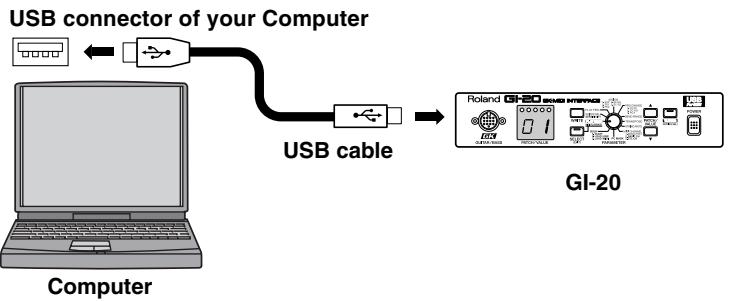
flowchart
graph LR
    A["Computer"] -->|USB connector of your Computer| B["USB cable"]
    B --> C["GI-20"]
2. Switch ON the GI-20's power switch.
3. In the "Opcode" folder in the location where OMS is installed, open the "OMS Applications" folder, and double-click the "OMS Setup" icon.

OMS Setup
* If the "Apple Talk" dialog box appears, click [Turn It Off]. Then, in the dialog box that appears next, click [OK].

NOTE
If you are using the GI-20 with a sequencer, do not disconnect the MIDI cable connected to the GI-20 while a song is playing back.
- The "Create a New Studio setup" dialog box will appear. Click [OK].
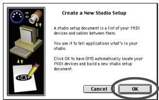
- The "OMS Driver Search" dialog box will appear. Click [Search].
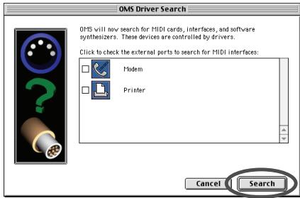
- After the search has been completed, make sure that "Roland GI-20" is listed in the "OMS Driver Setup" dialog box, and click [OK].
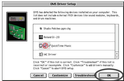
- After making sure that the Roland GI-20 is listed in the "OMS MIDI Device Setup" dialog box, click check box to check mark, and click [OK].
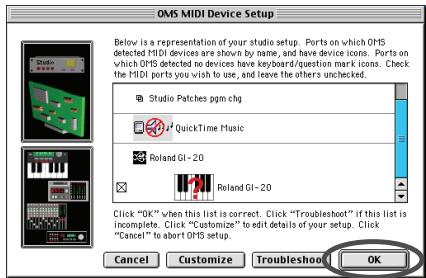
- The "Save" dialog box will appear. Input the desired file name, and click [Save].
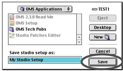
MEMO
If the "Create a New Studio setup" dialog box does not appear, click [New Studio setup] in the [File] menu.
NOTE
If an error dialog box is displayed during the setup, disconnect all MIDI cables connected to the GI-20, and make the OMS settings once again.
Installing & Setting Up the Driver (Macintosh)
The "Studio Setup" window will open.
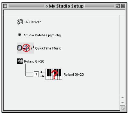
- Change the device name to "GK IN/MIDI OUT" for the MIDI device connected to the GI-20.
Click the device name, and you will be able to change it.
- Turn on the power of the MIDI device connected to the GI-20.
- Set the GI-20's PLAYBACK to ON (p. 17).
- If a sound module is connected to a MIDI connector of the GI-20, select [Test Studio] in the [Studio Menu] and check it in order to Test Studio whether sound is produced.
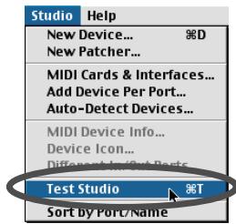
- In the "My Studio Setup Window," click the keyboard icon.
When you move the mouse cursor near the keyboard icon, the cursor will change to the shape of an eighth note. Verify that you can hear sound from your sound module.
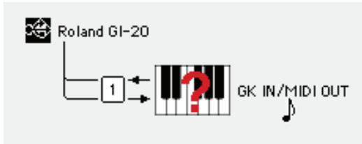
flowchart
graph TD
    A["Roland GI-20"] --> B["1"]
    B --> C["Q"]
    C --> D["GK IN/MIDI OUT"]
* The device displayed as “Roland GI-20” indicates the GI-20 itself; this device does not perform MIDI input or output. Use “GK IN/MIDI OUT” to send/receive MIDI data to/from the equipment connected to the MIDI IN/OUT connector of the GI-20.
- After you have finished the above check, exit OMS Setup.
This completes driver settings.
NOTE
The following step will cause a relatively loud sound to be produced by the sound module, so turn down the volume of your sound module before continuing.
■ FreeMIDI settings
1. Connect the GI-20 to your computer.
1) With the power switch turned OFF, connect the AC adaptor to the GI-20.
2) Connect the AC adaptor to an electrical outlet.
3) Use the USB cable to connect the GI-20 to your computer.
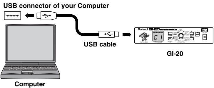
flowchart
graph TD
    A["Computer"] -->|USB connector of your Computer| B["USB cable"]
    B --> C["GL-20 Interface"]
2. Open the "FreeMIDI Applications" folder, and double-click the "FreeMIDI Setup" icon.

3. The first time FreeMIDI is started up, a "Welcome to FreeMIDI!" dialog box will appear. Click [Continue].
If this is the second or later time, select "FreeMIDI Preferences" from the File menu.
4. In the "FreeMIDI Preferences" dialog box, check "GI-20 Port" which is located below GI-20 Driver in MIDI Configuration, and click [OK].
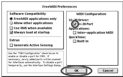
5. The "About Quick Setup" dialog box will appear. Click [Continue].
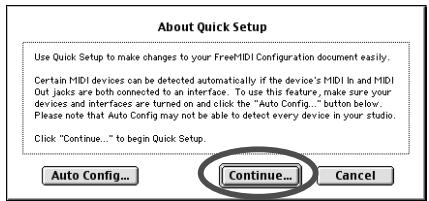
MEMO
If the dialog box does not show "GI-20 Driver," check whether the GI-20 is connected correctly, and start up FreeMIDI Setup once again.
MEMO
If the "About Quick Setup" dialog box is not displayed, select Quick Setup... from the Configuration menu.
- In the dialog box that appears, select the MIDI equipment that is connected to each port of the GI-20, and click [>>Add>>].
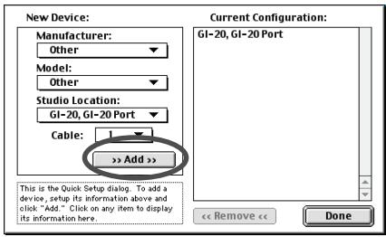
Manufacturer:
Select the manufacturer of your MIDI equipment. If the appropriate manufacturer does not appear in the list, select "Other."
Model:
Select the model of your MIDI equipment. If the appropriate model does not appear in the list, select "Other."
Studio Location:
Select "GI-20."
- When settings are complete, click [Done].
A setting window like the following will appear.
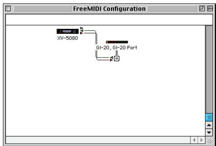
flowchart
graph TD
    A["XY-5080"] --> B["G1-20, G1-20 Port"]
    B --> C["Port"]
- If you selected "Other" for Model, double-click the appropriate icon in the setting window to make settings for your MIDI equipment.
(For details refer to the documentation included with your software.)
- From the File menu, select [Save], and save your settings.
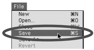
This completes driver settings.
NOTE
This is one example of a setting window. The window that appears will depend on your setup.
Troubleshooting

Problems common to Windows and Macintosh

Problems occurring only in Windows

Problems occurring only in Macintosh
Problems related to the USB driver

Cannot install the driver correctly
☐ Is the CD-ROM correctly inserted into your CD-ROM drive?
Installation is not possible unless the CD-ROM included with the GI-20 is inserted in your CD-ROM drive. Make sure that the CD-ROM is correctly inserted into your CD-ROM drive.
☐ Is the CD-ROM or the lens of the CD-ROM dirty?
If the CD-ROM or the lens of the CD-ROM drive is dirty, the installer may not work correctly. Clean the disc and/or lens using a commercially-available CD cleaner or lens cleaner.
☐ Are you installing the software from a networked CD-ROM drive?
The software cannot be installed from a networked CD-ROM drive.
☐ Is there sufficient free space on your hard disk?
Delete unneeded files to increase the amount of free space. After deleting the unneeded files, empty the recycling bin.
☐ Is the GI-20 connected correctly?
Make sure that the USB connector of your computer is connected to the GI-20 by a USB cable. Check this, and if you are using Windows, close the Sound and Multimedia Properties dialog box (Sounds and Audio Devices Properties in Windows XP, and Multimedia Properties in Windows 98), re-open the same dialog box once again, and specify the audio and MIDI input/output destinations.
→ "MIDI input and output destinations"(p. 57).
☐ Is the power of the GI-20 turned on?

☐ Using the procedure for "Deleting the driver"(p. 67), delete the USB audio device driver installed in your computer, and then re-install the GI-20 driver as described in "Installing & setting Up the Driver (Windows)"(p. 46).
Also check whether there is any “Other devices” in “Device Manager” or “Unknown device” in “Universal Serial Bus Controllers”. If you find any, delete them.

☐ Is OMS or FreeMIDI installed?
The GI-20 driver cannot be installed unless OMS or FreeMIDI are installed. Please install OMS or FreeMIDI.

GI-20 is not detected when making OMS or FreeMIDI settings
Is the GI-20 detected?
Turn the power of the GI-20 off, then on again.
Reconnect the USB cable.
If other USB devices are connected, connect only the GI-20.
It is possible that the Macintosh did not correctly detect and initialize the GI-20. Leave the GI-20's USB cable connected, and restart your Macintosh. If it is still not detected, shut down your Macintosh, and then restart it.
The GI-20 will not be detected if it is connected to the USB connector on the Macintosh keyboard.
Please connect the GI-20 to a USB connector on the Macintosh itself.
Are you using only OMS?
OMS will not work properly if FreeMIDI is installed in the same system. Delete FreeMIDI-related files from the Extensions folder.

"Find new hardware wizard" does not execute automatically

The "Insert Disk" dialog box does not appear

"Find new hardware wizard" ends before the process is completed
☐ It may take about 15 seconds (or more) after the USB cable is connected for the GI-20 to be detected.
☐ Is the USB cable connected correctly?
Make sure that the GI-20 and your computer are correctly connected via a USB cable.
☐ Is USB enabled on your computer?
Refer to the operation manual for your computer, and make sure that USB is enabled.
☐ Does your computer meet the USB specifications?
If you are using a computer that does not fulfill the electrical requirements of the USB specifications, operation may be unstable. In this case, you may be able to solve the problem by connecting a USB hub.
If the above actions do not solve the problem, it is possible that the GI-20 has been incorrectly detected by the computer.
As described in "
→ "Installing & Setting Up the Driver (Windows)" (p. 46)

"Found unknown device" appears even though you installed the driver
If your computer or USB hub has two or more USB connectors, and you connect the GI-20 to a USB connector to which the GI-20 has never been connected before, the “Unknown device” dialog box may appear even on a computer onto which you have already installed the driver.
Refer to "Installing & Setting Up the Driver (Windows)"(p. 46), and install the driver once again. This is not a malfunction.
If the “Found unknown device” dialog box appears even though the GI-20 is connected to the same USB connector as before, it is possible that the computer has detected the GI-20 incorrectly.
As described in "
→ "Installing & Setting Up the Driver (Windows)" (p. 46)

An "Unknown driver found" dialog box appears, and you are unable to install the driver

Device Manager shows “?”, “!”, or “USB Composite Device”

Driver is not installed correctly
It is possible that the computer has detected the GI-20 incorrectly.
As described in "
→ "Installing & Setting Up the Driver (Windows)" (p. 46)
-
Turn off the power of your computer, and start up Windows with all USB cables disconnected (except for keyboard and mouse).
-
After Windows restarts, use a USB cable to connect the GI-20 to your computer.
-
Turn on the power of GI-20.
-
Click the Windows [Start] button, and from the menu that appears, choose "Settings | Control Panel."
-
Double-click the "System" icon. The "System Properties" dialog box will appear.
-
In Windows XP/2000, select the System Properties Hardware tab, and click Device Manager. In Windows 98, Click the "Device Manager" tab.
-
Check whether "Roland GI-20" with an "!" or "?" symbol is displayed below "Other Devices," "Sound, Video, and Game Controllers," or "Universal Serial Bus Controller." If you find any such indication, select it and click [Delete].
-
A dialog box will ask you to confirm deletion of the device. Verify the contents of the dialog box, and then click [OK]. In the same way, delete all occurrences of "Roland GI-20" that have an "!" or "?" symbol.
-
Check whether "Composite USB Device," "USB Device," or "USB Composite Device" with an "!" or "?" symbol is displayed below "Other Devices," "Sound, Video, and Game Controllers," or "Universal Serial Bus Controller." If you find any such indication, you need to determine whether it has appeared because the GI-20 has been detected incorrectly, or because there is a problem with some other device. To determine this, switch off the power of the GI-20.
If the “Composite USB Device” (or other) indication disappears when you turn off the power of the GI-20, then it is the GI-20 that has been incorrectly detected.
Return to step 2 and continue the procedure, and when you reach step 8, delete the information that was detected incorrectly.
If the indication does not disappear when you turn off the power of the GI-20, then this indication refers to a different device. Do not delete it.
"Composite USB Device," "USB Device," or "USB Compatible Device" may sometimes indicate a device other than the GI-20. Be careful not to accidentally delete the registration for another device. If you delete the registration for another device, you will have to reinstall the driver for that device.
- A dialog box will ask you to confirm deletion of the device. Verify the contents of the dialog box, and click [OK]. Delete each unwanted occurrence of "Composite USB Device," "USB Device," or "USB composite device" indications with an "!" or "?" symbol.
- When you have finished deleting unwanted device, click [OK] in "System Properties" dialog box.
- Disconnect the USB cable from the GI-20.
- Restart Windows.
* If the problem still occurs after you have taken the above measures, please refer also to the Readme file for the USB driver. The Readme file is on the CD-ROM.

Can't install/delete/use the driver in Windows XP/2000
☐ Did you log on to Windows as a user with administrative privileges?
In order to install/delete/re-install the driver in Windows XP/2000, you must be logged into Windows as a user with administrative privileges, such as Administrator. For details, please contact the system administrator for your computer system.
☐ Did you make "Driver Signing Options"?
In order to install/re-install the driver, you must make "Driver Signing Options".
(Windows XP→p. 46, Windows 2000 → p. 51)

Windows XP/2000 displays a "Hardware Installation" or "Digital Signature Not Found" dialog box
☐ Did you make "Driver Signing Options"?
In order to install/re-install the driver, you must make the settings described in "Driver Signing Options".
(Windows XP→p. 46, Windows 2000 → p. 51)
Deleting the driver
If you were unable to install the driver according to the procedure given, the GI-20 may not be recognized correctly by the computer. In this case, use the following procedure to delete the driver, and then follow the procedure in “Installing & Setting Up the
Driver"(Windows: p. 46, Macintosh: p. 59) to install the driver once again.
Windows XP/2000 users
In order to delete (uninstall) the driver, a user with administrative privileges such as Administrator must be logged onto Windows. For details, contact the system administrator of your computer.
- Start Windows with all USB cables disconnected. (except the keyboard and mouse)
- Log on to Windows as one of the following users:
• a user whose account type is Computer Administrator
- the Administrator or other user with the privileges of the Administrators group
- Use a USB cable to connect the GI-20 and your computer.
- Turn the POWER switch of the GI-20 to the "ON" position.
- Exit all applications before performing the uninstallation.
- Delete the driver.
1) Open the "Control Panel" and double click on "System."
* If the above icon cannot be found, click the "Performance and Maintenance," and click the "System."
2) Click the "Hardware" tab, and then click the "Device Manager" button.
3) Double-click "Sound, video, and game controllers" to see the list of devices.
4) From the list, right-click "Roland GI-20." Then choose "Uninstall" from the menu that appears.
* If the list does not show "Roland GI-20," refer to "Can't install/delete/use the driver in Windows XP/2000."
5) A "Confirm Device Removal" dialog box will appear. Make sure that "Roland GI-20" is shown in the dialog box, and click the [OK] button.
6) Close the "Device Manager," and in "System Properties" click the [OK] button.
- Disconnect the USB cable from the GI-20.
- Restart Windows.
Windows Me/98 users
- Start Windows with all USB cables disconnected. (except the keyboard and mouse)
- Use a USB cable to connect the GI-20 and your computer.
- Turn the POWER switch of the GI-20 to the "ON" position.
- Exit all applications before performing the uninstallation.
- Delete the driver.
1) Open the "Control Panel," and double-click "System."
* If the above icon cannot be found, click the "view all Control Panel options." in "Control Panel."
2) Click the "Device Manager" tab.
3) Double-click "Sound, video and game controllers" to see the list of devices.
4) From the list, select "Roland GI-20" and click "Remove."
* If the list does not show “Roland GI-20,” refer to “
5) A "Confirm Device Removal" dialog box will appear. Make sure that "Roland GI-20" is shown in the dialog box, and click the [OK] button.
6) In "System Properties," click "Close."
-
Disconnect the USB cable from the GI-20.
-
Change the "Folder Options" settings.
1) Click "Start" → "Settings" → "Folder Options," and click the "View" tab.
2) In "Advanced settings," uncheck "Hide file extensions for known file types" and check "Show all files" in "Hidden files." Then click the [OK] button.
1) Open the "Control Panel," and double-click "Folder Options." Then click "View" tab.
* If the above icon cannot be found, click the "view all Control Panel options." in "Control Panel."
2) In "Advanced settings," uncheck "Hide file extensions for known file types" and check "Show hidden files and folders" in "Hidden files and folders." Then click the [OK] button.
- Delete the driver settings files.
1) Start up the Explorer, select "\Windows\Inf\Rdif0032.inf" (if it exists). Right-click and choose "Delete" from the menu that appears.
2) If "\Windows\Inf\Other\RolandRdif0032.inf" exists, select it, right-click, and choose "Delete" from the menu that appears.
3) In the “\Windows\System” folder, successively “Rddp0032.dat,” “Rddv0032.drv,” “Rdvx0032.vxd,” and “Rdwm0032.sys,” and for each file, right-click and choose “Delete” from the menu that appears.
- Restart Windows.
Macintosh users
- Turn off the power of the GI-20. Also disconnect the USB cable (by which the GI-20 is connected) from your Macintosh.
- From the system extensions folder, drag "USB GI-20 Driver" into the trash to delete it.
- Delete GI-20 from the OMS Folder inside the System folder, or drag GI-20 Driver from the FreeMIDI Folder to the trash.
- Restart the Macintosh.
A
AC Adaptor 7
ASSIGN 13, 19–20
Assign 14,23
B
Bank Select 9,25,29
Basic Channel (BASIC CH) 14–15
Bend 9
BEND DATA THIN 13,31
BEND RANGE 13, 20, 22–24
BEND RANGE MAX 13, 22, 24, 32
BULK 29–31
Bulk Dump 29
Bulk Load 29-31
C
Chromatic 24
Control Change 9,20,23,25,32
Control Channel (CTL CH) 15–16
Copy 27
Cord Hook 7
D
Display 6,13
Driver 17,33,45
E
Error Message 15, 32, 37
Exclusive Message 29
EXIT 6
Expression Pedal (EXP PDL) 7, 15, 19–20, 32
F
Factory Reset 34
FOOT SW jack 19
Foot Switch (FOOT SW) 7, 15, 19–20, 23, 32
G
GENERIC 33
GK IN 6,17
GK VOL (Volume) 15, 19–20
Glide 14, 20–23, 32
GM 13
GUITAR OUT 7
GUITAR SEL 11, 13, 18
GUITAR/BASS 7,10,34
H
Hold 21
|
Indicator 12
Input Sensitivity 11, 18
L
LOAD (MIDI) 30
LOAD (USB) 31
M
MASTER TUNE 12, 28
MIDI 7,9
MIDI BASIC CH 12
MIDI CHANNEL 14
MIDI Channel 14
MIDI CTL CH 12
MIDI IN 7,15,17
MIDI OUT 7,15,17,28
MIDI PLAYBACK 13, 17
MIDI Port 17
MIDI Sound Module 9,11
MIDI Transmit Channel 14
MONO (Mono Mode) 14, 25, 32
MONO/POLY 13-14
N
Note Off 9
Note On 9
O
Octave 21
Omni 15
P
PARAMETER 6
Patch 12–13, 20–21, 23, 26–27
Patch Number 13
Patch Parameter 12
PATCH/VALUE 6
PC MASK 12, 25, 29
Pitch Bend 14, 20, 22–23, 32
Pitch Bend Message 31
Pitch Bend Sensitivity 23
PLAY FEEL 13, 19
PLAY MODE 12, 16, 27
POLY (Poly Mode) 14, 20, 22–23, 25
Power (POWER) 6,11
PRG CHANGE 13,25
Program Change 9, 16, 25, 29
R
Rack Mount Adaptor 34
RECEIVE CONTROL CHANGE DATA THIN ...... 13, 32
RPN Channel Fine Tuning 28
Rubber Foot 34
Index
S
S1/S2 Switch 15, 19–20
SELECT (EXIT) 6, 26–27, 29–30
Sensitivity (SENSITIVITY) 6, 11–12
STRING MUTE 13,26
STRING SEL 6
System Exclusive 9
System Parameter 12
T
Transmission Mode 14, 20, 22–23, 25, 32
TRANSPOSE 13,23
Tuner 6,26,28
TUNER (STRING SEL) 23, 25–26, 28, 34
Tuner Indicator 6
Tuning 28
U
USB 7,10,17,31
USB Driver 33
USB DRIVER TYPE 13
USB MIDI Driver 45
V
VENDER SPECIFIC 33
Vibrato 14, 20, 22
W
WRITE 6,30
For EU Countries

The Ground Truth image displays a single, solid horizontal line. According to Rule 2 (UNDERSCORE & LINE RULES), this is a stylistic or background line, not a placeholder underscore. Therefore, the OCR result must ignore it and output nothing or only meaningful text. The provided OCR content is "____", which consists of four underscores. This is an incorrect interpretation of the line as a placeholder, violating the rule that stylistic lines must be ignored. The OCR has hallucinated underscores where none should exist based on the GT's visual context. Hence, the OCR result is inconsistent with the Ground Truth.

This symbol indicates that in EU countries, this product must be collected separately from household waste, as defined in each region. Products bearing this symbol must not be discarded together with household waste.

This product complies with the requirements of EMC Directive 2004/108/EC.
For the USA
FEDERAL COMMUNICATIONS COMMISSION RADIO FREQUENCY INTERFERENCE STATEMENT
This equipment has been tested and found to comply with the limits for a Class B digital device, pursuant to Part 15 of the FCC Rules. These limits are designed to provide reasonable protection against harmful interference in a residential installation. This equipment generates, uses, and can radiate radio frequency energy and, if not installed and used in accordance with the instructions, may cause harmful interference to radio communications. However, there is no guarantee that interference will not occur in a particular installation. If this equipment does cause harmful interference to radio or television reception, which can be determined by turning the equipment off and on, the user is encouraged to try to correct the interference by one or more of the following measures:
– Reorient or relocate the receiving antenna.
– Increase the separation between the equipment and receiver.
- Connect the equipment into an outlet on a circuit different from that to which the receiver is connected.
- Consult the dealer or an experienced radio/TV technician for help.
This device complies with Part 15 of the FCC Rules. Operation is subject to the following two conditions:
this device may not cause harmful interference, and
this device must accept any interference received, including interference that may cause undesired operation.
Unauthorized changes or modification to this system can void the users authority to operate this equipment.
This equipment requires shielded interface cables in order to meet FCC class B Limit.
For Canada
NOTICE
This Class B digital apparatus meets all requirements of the Canadian Interference-Causing Equipment Regulations.
AVIS
This product contains chemicals known to cause cancer, birth defects and other reproductive harm, including lead.
AFRICA
EGYPT
Al Fanny Trading Office
9, EBN Hagar Al Askalany
Street,
ARD E1 Golf, Heliopolis,
Cairo 11341, EGYPT
TEL: (022)-418-5531
REUNION
Royal Cape Park, Unit 24
Londonderry Road, Ottery 7800
Cape Town, SOUTH AFRICA
TEL: (021) 799 4900
ASIA
CHINA
Roland Shanghai Electronics
Co., Ltd.
5F. No.1500 Pingliang Road
Shanghai 200090, CHINA
TEL: (021) 5580-0800
Roland Shanghai Electronics
Co., Ltd.
(BEIJING OFFICE)
10F. No.18 3 Section Anhuaxili
Chaoyang District Beijing
100011 CHINA
TEL: (010) 6426-5050
HONG KONG
Tom Lee Music Co., Ltd.
Service Division
22-32 Pun Shan Street, Tsuen
Wan, New Territories,
HONG KONG
TEL: 2415 0911
Parsons Music Ltd.
8th Floor, Railway Plaza, 39
Chatham Road South, T.S.T,
Kowloon, HONG KONG
TEL: 2333 1863
INDIA
Rivera Digitec (India) Pvt. Ltd.
411, Nirman Kendra
Mahalaxmi Flats Compound
Off. Dr. Edwin Moses Road,
Mumbai-400011, INDIA
TEL: (022) 2493 9051
INDONESIA
PT Citra IntiRama
Suoi Nhac Company, Ltd
370 Cach Mang Thang Tam St.
Dist.3, Ho Chi Minh City,
VIET NAM
TEL: 9316540
PHILIPPINES
G.A. Yupangco & Co. Inc.
339 Gil J. Puyat Avenue
Makati, Metro Manila 1200,
PHILIPPINES
TEL:(02) 899 9801
SINGAPORE
SWEE LEE MUSIC
COMPANY PTE. LTD.
150 Sims Drive,
SINGAPORE 387381
TEL: 6846-3676
TAIWAN
ROLAND TAIWAN
ENTERPRISE CO., LTD.
Room 5, 9fl. No. 112 Chung
Shan N.Road Sec.2, Taipei,
TAIWAN, R.O.C.
TEL: (02) 2561 3339
THAILAND
Theera Music Co., Ltd.
100-108 Soi Verng
Nakornkasem, New
Road, Sumpantawongse, Bangkok 10100 THAI JIA
Bangkok 10100 THAILAND TEL: (02) 224-8821
TEL. (02) 2246
AUSTRALIA/ NEW ZEALAND
AUSTRALIA/
NEW ZEALAND
Roland Corporation
Australia Pty., Ltd.
38 Campbell Avenue
Dee Why West. NSW 2099
AUSTRALIA
For Australia
Tel: (02) 9982 8266
For New Zealand
Tel: (09) 3098 715
CENTRAL/LATIN AMERICA
ARGENTINA
Instrumentos Musicales S.A.
Av.Santa Fe 2055
(1123) Buenos Aires
ARGENTINA
TEL: (011) 4508-2700
BARBADOS
A&B Music Supplies LTD
12 Webster Industrial Park
Wildey, St.Michael, Barbados TEL: (216) 428-1133
TEL: (246)430-1100
BRAZIL
Roland Brasil Ltda.
Rua San Jose, 780 Sala B
Parque Industrial San Jose
Cotia - Sao Paulo - SP, BRAZIL
TEL: (011) 4615 5666
CHILE
Comercial Fancy II S.A.
Rut.: 96.919.420-1
Nataniel Cox #739, 4th Floor
Santiago - Centro, CHILE
TEL: (02) 688-9540
COLOMBIA
Centro Musical Ltda.
Cra 43 B No 25 A 41 Bododega 9
Medellin, Colombia
TEL: (574)3812529
COSTA RICA
JUAN Bansbach Instrumentos
Musicales
Boulevard Andrews, Albrook,
Panama City, REP. DE
PANAMA
TEL: 315-0101
PARAGUAY
Distribuidora De
Instrumentos Musicales
J.E. Olear y ESQ. Manduvira
Asuncion PARAGUAY
TEL: (595) 21 492147
Audionet
155, New National Road
Patras 26442, GREECE