
7CFE-130IX - Built-in oven FAGOR - Free user manual and instructions
Find the device manual for free 7CFE-130IX FAGOR in PDF.

| Product type | Built-in hood (built-in oven category) |
| Brand | FAGOR |
| Model | 7CFE-130IX |
| Dimensions (W x D x H) | Approximately 60 x 50 x 15 cm (estimate) |
| Weight | Approximately 8 kg (estimate) |
| Power supply | 230 V ~ 50 Hz (check on the label) |
| Motor power | Not specified, multiple speeds |
| Lighting | E14 bulb, max 40W |
| Grease filter | Metal, dishwasher safe (65°C), unlimited lifespan |
| Charcoal filter | Replace every 4 months (non-washable) |
| Suction speeds | Multi-speed (sliding switches) |
| Evacuation | External (duct) or recirculation (charcoal filter) |
| Minimum distance from cooking surface | 65 cm (electric) / 75 cm (gas or mixed) |
| Exterior maintenance | Cloth dampened with alcohol or neutral liquid detergent, every 10 days |
| Safety | Unplug before maintenance; do not flambé under the hood |
| Noise level | Not specified |
| Material | Stainless steel (visible parts) |
| Removable visor | Yes |
| Warranty | According to manufacturer's conditions |
Frequently Asked Questions - 7CFE-130IX FAGOR
User questions about 7CFE-130IX FAGOR
0 question about this device. Answer the ones you know or ask your own.
Ask a new question about this device
Download the instructions for your Built-in oven in PDF format for free! Find your manual 7CFE-130IX - FAGOR and take your electronic device back in hand. On this page are published all the documents necessary for the use of your device. 7CFE-130IX by FAGOR.
USER MANUAL 7CFE-130IX FAGOR
natural_image
Technical line drawing of a 3D mechanical housing or enclosure with internal perforations and mounting holes (no text or symbols)E Montaje y modo de empleo
P Instruções para montagem e utilização
F Prescriptions de montage et mode d'emploi
GB Instruction on mounting and use
D Montage- und Gebrauchsanweisung
© CZ Instrukce pro montáž a použití
SK Inštrukcie k montáži a použitie
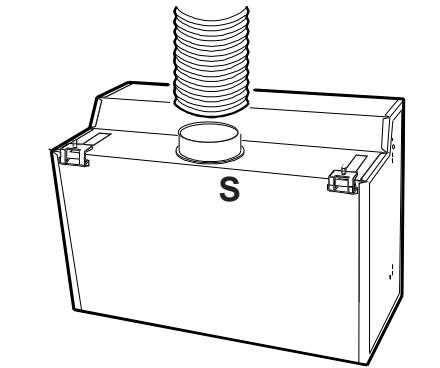
Instalación Operaciones preliminares - Fig. 1
Instalação Operações preliminares - Fig. 1
Montage Opérations préliminaires - Fig. 1
Installation preliminary operations - Fig. 1
Montage Einleitende Maßnahmen - Fig. 1
Instalace Předběžné úkony - Obr. 1
Inštalácia Predbežné operácie - Obr. 1
natural_image
Technical line drawing of a mechanical component with a threaded spring and base, labeled 'S' (no text or symbols beyond label)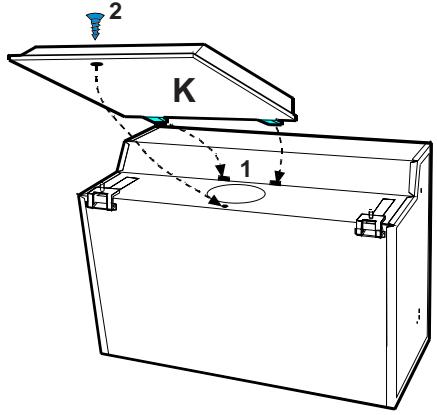
Instalación Montaje del panel decorativo - Fig. 2
Instalação Montagem do painel decorativo - Fig. 2
Montage Montage panneau décoratif - Fig. 2
Installation Decorative panel assembly - Fig. 2
Montage Montage der Dekorplatte - Fig. 2
Instalace Upevnit čelní panel - Obr. 2
Inštalácia Montáž zberača pary amriežka - Obr. 2
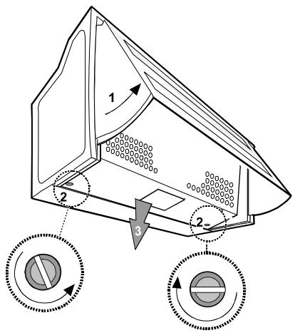
Installation Wall unit mounting - Fig. 3
Montage Montage am Oberschrank - Fig. 3
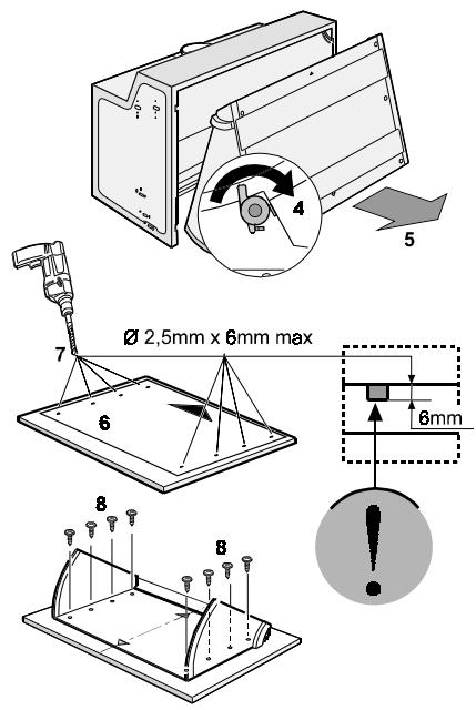
Installation Wall mounting - Fig. 4
Montage Montage an der Wand - Fig. 4
natural_image
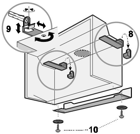
Diagram of a bed tray with labeled sections (s, t) and a curved arrow indicating direction (no text or symbols beyond labels)Fig. 8 - Abb. 8 - Obr. 8
natural_image
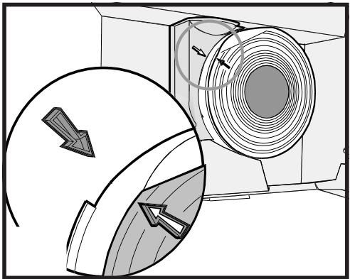
Technical diagram of a mechanical component with directional arrows indicating motion or flow (no text or symbols present)Fig. 9 - Abb. 9 - Obr. 9
Empleo: dos posibilidades
Use: Two systems are available
Exhaust mode
Vapours are extracted outside through an exhausting pipe that is affixed to the connection ring above the hood (Fig. 1-S).
Diameter of the exhausting pipe must be equal to that of the connection ring.
In the horizontal runs the exhausting pipe must be slightly slanted (about 10^ ) and directed upwards to vent the air easily from the room to the outside.
If the hood is supplied with carbon filter, then it must be removed.
Filter version
The air is filtered through a carbon filter (for its montage see paragraph "Carbon filter") and recirculated into the room through the baffle (Fig.1-K).
If the hood is not supplied with carbon filter, then it must be ordered and mounted.
This version is used when there is no exhausting pipe for venting outdoors or when it is impossible to install one.
Installation - Fig. 2-3-4-5
When installed, the distance between hood and burners must be not less than 65 cm. above electric burners or 75 cm. above gas or mixed-fuel burners.
The best performance of the unit is obtained in the exhaust mode.
The best performances are obtained with short pipes (max. 4 m) and with few curves.
Electric connection (not for UK)
Before completing any connection, make sure the house voltage corresponds with the voltage indicated on the label affixed inside the hood.
It is advisable to call a qualified technician to make the electrical connection.
Appliance fitted with plug.
Connect it to a socket which conforms with current regulations. If you intend to connect it directly to the electric mains, remove the plug and fit an approved bipolar switch with a minimum contact opening of no less than 3mm. If the plug is not accessible once it has been inserted in the socket, it will however be necessary to fit an approved bipolar switch with a minimum contact opening of no less than 3mm.
Appliance without plug
Fit an approved plug or an approved bipolar switch with a minimum contact opening of not less than 3mm.
The manufacturers are not liable for any problems caused by the user's failure to observer the above instructions.
Electric connection only for UK WARNING: This appliance is double insulation and must not be earthed.
The manufacturers will not accept liability for any problems however caused by the failure of the user or installer to comply with these instruction or with safety regulations.
It is recommended that installation is carried out by a qualified electrician.
This appliance is intended to be permanently connected to the electrical supply trough a double-pole switched fused spur - (disconnector) - fitted with a 3 or 5 amp fuse. The opening distance between the switch contacts shall not be less than 3 mm. The installation must conform to the requirements of BS 7671.
The wires in the mains lead are coloured in accordance with the following code:
Blue Neutral:-To be connected to the supply terminal marked 'N' or coloured Black.
Brown live: - To be connected to the supply terminal marked 'L' or coloured Red.
This appliance is not intended to be connected to the electrical supply through a plug and socket, but if for any reason a plug should be fitted, then it must be wired according to the colour code as shown above.
Warning Ensure that the appliance is isolated from the supply before carrying out installation.
Description of the hood - Fig. 6
- Pull-out steam deflector
- Control panel.
- Grease filter (inside the extractor grille).
- Lighting unit.
- Extractor grille.
Using the hood
— The hood is provided with a motor with several speeds.
For the best performance, we recommend using the low speeds in normal conditions and the high speeds in particular cases of strong odour and vapour concentration.
— We recommend starting up the hood a few minutes before cooking and keeping it running until all the odours have been eliminated.
Slider switches panel
Two are the switches: one for lighting ON and OFF the lamps; one for lighting ON and selecting suctions power.
With speed selected, closing the steam deflector switches off the hood. Opening the steam deflector switches it on again.
Warning!
— This appliance is designed to be operated by adults. Children should not be allowed to tamper with the controls or play with the appliance.
— The hood cannot be connected to flues of other appliances that run on energy sources other than electricity.
— When the hood is used at the same time of other appliances that run on energy sources other than electricity, provision must be made for an adequate supply of air.
— No food must be cooked flambé underneath the hood.
The use of an unprotected flame is dangerous for the filters and could cause fires.
Therefore, never use an open flame under the hood. When frying foods, never leave the pan alone because the cooking oil could flare up.
— Please, keep to the provisions of official directives regarding the question of fume discharge.
— The manufacturers refuse to accept any responsibility for damage to the hood or its catching on fire because of failure to observe the above instructions.
Maintenance
Before performing any maintenance operation, isolate the hood from the electrical supply by switching off at the connector and removing the connector fuse.
Or if the appliance has been connected through a plug and socket, then the plug must be removed from the socket.
Metal grease filter
The metal grease filter serves to trap particles of grease through suspension.
The metal grease filter lasts forever and must be washed either by hand or in the dishwasher (65°C) with suitable detergents.
When washed in a dish washer, the grease filter may discolour slightly, but this does not affect its filtering capacity. The metal grease filters must be washed at least once a month.
To remove the metal grease filter (Fig. 7-8):
Disconnect the hood from the electricity.
a) Pull out the steam deflector.
b) Turn the side knobs 90°.
c) Remove the extractor grille
d) Remove the dirty grease filter (Fig. 8 - the grease filter is fixed to the extractor grille with clips which unfasten to allow extraction of the filter).
After cleaning the metal grease filter, remount in reverse order, making sure the entire extraction surface is covered. Let the filter dry without damaging it before putting it back into place.
Carbon filter
This filter dissolves cooking odours.
The carbon filter must never be washed. It should be changed every 4 months in normal use.
Mounting and replacing the carbon filter:
Disconnect the hood from the electricity.
a) Pull out the steam deflector.
b) Remove the extractor grille (Fig. 7).
c) If the carbon filter is not mounted, mount the filters over the motor protection grille and line up the plastic reference tab on the carbon filter with the reference mark on the fan shroud and turn clockwise until it locks. (Fig. 9).
d) If the carbon filter is already mounted and needs to be removed, turn anticlockwise until it unlocks.
e) Remount the extractor grille.
Cleaning
To clean the outside of the hood use a cloth moistened with denatured alcohol or neutral liquid detergents.
Never use products containing abrasive.
Wipe brushed stainless steel in the same direction as the brushing to avoid scratching.
Clean the external surface of the cooker hood almost once every 10 days.
Attention
Failure to observe the rules for cleaning the appliance and changing and cleaning the filters may cause fires.
Therefore, we recommend observing these instructions.
Replacing the lamp
Disconnect the hood from the electricity.
a) Pull out the steam deflector.
b) Remove the extractor grille (Fig. 7).
c) Always replace burnt-out lamp with 40Watt max. (E14) lamp.
d) Remount the extractor grille.
e) Before calling for repair service because the hood fails to light up, make sure the bulbs are screwed in tightly.
- Empleo: dos posibilidades
- Exhaust mode
- Filter version
- Installation - Fig. 2-3-4-5
- Electric connection (not for UK)
- Appliance fitted with plug.
- Appliance without plug
- Electric connection only for UK WARNING: This appliance is double insulation and must not be earthed.
- Description of the hood - Fig. 6
- Using the hood
- Slider switches panel
- Warning!
- Maintenance
- Metal grease filter
- To remove the metal grease filter (Fig. 7-8):
- Carbon filter
- Mounting and replacing the carbon filter:
- Cleaning
- Attention
- Replacing the lamp
Brand : FAGOR
Model : 7CFE-130IX
Category : Built-in oven