
DKE995P - Range hood BOSCH - Free user manual and instructions
Find the device manual for free DKE995P BOSCH in PDF.


| Product type | Kitchen hood |
| Brand | Bosch |
| Model | DKE995P |
| Dimensions (W x D x H) | 90 cm x 50 cm x 60 cm |
| Net weight | 15 kg |
| Power supply | 220-240 V, 50 Hz |
| Motor power | 250 W |
| Lighting | LED, 2 x 3 W |
| Max extraction power | 700 m³/h |
| Max noise level | 65 dB |
| Energy class | A+ |
| Number of speeds | 4 + intensive speed |
| Control type | Touch |
| Evacuation type | Recirculation or external evacuation |
| Grease filter | Aluminum, dishwasher safe |
| Charcoal filter | Optional, flexible model |
| Maintenance | Clean filters every month |
| Exterior cleaning | Soft cloth and mild detergent |
| Special functions | Filter saturation indicator, delayed shut-off |
| Spare parts | Filters, bulbs, remote control available |
| Repairability | Repairability index 8.0/10 |
| Warranty | 2 years |
Frequently Asked Questions - DKE995P BOSCH
User questions about DKE995P BOSCH
0 question about this device. Answer the ones you know or ask your own.
Ask a new question about this device
Download the instructions for your Range hood in PDF format for free! Find your manual DKE995P - BOSCH and take your electronic device back in hand. On this page are published all the documents necessary for the use of your device. DKE995P by BOSCH.
USER MANUAL DKE995P BOSCH
DKE 995 P

Operating and installation instructions
Operating and installation instructions
Operating and installation instructions
Operating and installation instructions
Operating and installation instructions
Operating and installation instructions
Household Appliances
Page 3-15
Page 16-28
Pages 29-41
Pages 42-54
Pages 55-67
Pages 68-80
Pages 81-93
Fig. 1
GAS
GAZ
KAASU
GASS
ELECTRIC
ELECTR.
ELETT.
EL.


Recirculation mode

Before installation
Instructions for use:
Appliance description

Operating modes
Exhaust-air mode:
The extractor-hood fan extracts the kitchen vapours and conveys them through the grease filter into the atmosphere.
The grease filter absorbs the solid particles in the kitchen vapours.
The kitchen is kept almost free of grease and odours.
When the extractor hood is operated in exhaust-air mode simultaneously with a different burner which also makes use of the same chimney (such as gas, oil or coal-fired heaters, continuous-flow heaters, hot-water boilers) care must be taken to ensure that there is an adequate supply of fresh air which will be needed by the burner for combustion.
Safe operation is possible provided that the underpressure in the room where the burner is installed does not exceed 4 Pa (0.04 mbar).
Operating modes
This can be achieved if combustion air can flow through non-lockable openings, e.g. in doors, windows and via the air-intake/exhaust-air wall box or by other technical measures, such as reciprocal interlocking, etc.
If the air intake is inadequate, there is a risk of poisoning from combustion gases which are drawn back into the room.
An air-intake/exhaust-air wall box by itself is no guarantee that the limiting value will not be exceeded.
Note: When assessing the overall requirement, the combined ventilation system for the entire household must be taken into consideration. This rule does not apply to the use of cooking appliances, such as hobs and ovens.
Unrestricted operation is possible if the extractor hood is used in recirculating mode – with activated carbon filter.
Circulating-air mode:
☐ An activated carbon filter must be fitted for this operating mode (see Filters and maintenance).
⚠ The complete installation set and replacement filters can be obtained from specialist outlets. The corresponding accessory numbers can be found at the end of these operating instructions.
☐ The extractor-hood fan extracts the kitchen vapours which are purified in the grease filter and activated carbon filter and then conveyed back into the kitchen.
☐ The grease filter absorbs the grease particles in the kitchen vapours.
☐ The activated carbon filter binds the odorous substances.
Before using for the first time
Important notes:
☐ The Instructions for Use apply to several versions of this appliance. Accordingly, you may find descriptions of individual features that do not apply to your specific appliance. ☐ This extractor hood complies with all relevant safety regulations.
Repairs should only be carried out by qualified specialists.
Improperly executed repairs can give rise to significant hazards for the user.
☐ Before using your new appliance, please read these Instructions for Use carefully. They contain important information concerning your personal safety as well as on use and care of the appliance. ☐ Please keep the operating and installation instructions in a safe place; this important documentation may also be of use to a possible subsequent owner.
⚠ Do not use the appliance if it is damaged in any way
⚠ The appliance is not intended for use by young children or infirmed persons without supervision. Young children should be supervised to ensure they do not play with the appliance.
⚠ The appliance should only be connected up to the mains and taken into use by a qualified specialist.
Dispose of packaging materials properly (see Installation instructions).
Light bulbs must always be fitted when the extractor hood is in use.
Defective bulbs should be replaced immediately to prevent the remaining bulbs from overloading.
Never operate the extractor hood without a grease filter.
Overheated fat or oil can easily catch fire.
If you are cooking with fat or oil, e.g. chips, etc., never leave the cooker unattended.
Do not flambé food directly under the extractor hood.
Risk of grease filter catching fire due to flames.
Restrictions apply to the use of the extractor hood over a solid-fuel burner (coal, wood, etc.). (See Installation instructions).
Gas hobs / gas cookers
Always use gas hobs in a proper and safe manner.
Important:
The flames from the gas hob must always be covered by pots or pans.
The intense heat generated by the gas flames could cause damage to the extractor hood.
The heat load of all the hotplates which is produced during operation must not exceed 8.0 kW, irrespective of the installed nominal output.
Exception: The hotplates may be operated briefly (max. 15 minutes) at a heat load up to 11.3 kW if at least fan setting 2 has been permanently switched on. (Otherwise, there is a risk of burns if the housing surfaces are touched).
Operating procedure
The most effective method of removing vapours produced during cooking is to:
Switch the ventilator ON as soon as you begin cooking. Switch the ventilator OFF a few minutes after you have finished cooking.

Fan OFF Reduce fan speed Fan ON and increase speed
Acoustic signal:
When a button is pressed, this is verified by an acoustic signal.
Switching off the acoustic signal:
Simultaneously press buttons 0 and + until a signal is emitted after approx. 3 seconds.
Switching on the acoustic signal:
Repeat the process.
Setting the required fan speed:
Press the + button. The fan speed is increased by one step. Press the – button. The fan speed is reduced by one step.
Press the 0 button. The displayed goes out shortly afterwards.
Or:
Keep pressing the – button until the fan switches off. The displayed □ goes out shortly afterwards.
Intensive setting:
Maximum power is obtained at the intensive setting. It is only required for short intervals.
Keep pressing the + button until a P appears in the display. If the intensive setting is not cancelled by hand, the fan will automatically switch back to step 2 after 10 minutes.
Fan follow-on:
Press the →l button.
The fan continues to run at step 1 for 10 minutes, and at the same time a dot flashes in the display. After this period the fan switches off automatically.
Lighting:
Briefly press the ⚙ button to switch the light on and off. The light can be switched on at any time, even though the fan is switched off. Adjusting the brightness: Hold down the ⚙ button until the desired brightness is obtained.
Switching on the light automatically, e.g. via a timer:
Fan and light must be switched off.
Switching on:
Simultaneously press the – and →I buttons.
After approx. 3 seconds the light switches on to acknowledge the setting.
Switching off:
Repeat the process with the light switched on.
☐ After approx. 3 seconds the light switches off to acknowledge the setting.
Filters and maintenance
Grease filters:
Metal filters are used to trap the greasy element of the vapours that develop during cooking.
The filter mats are made from non-combustible metal.
Caution:
As the filter becomes more and more saturated with grease, not only does the risk of it catching fire increase but the efficiency of the extractor hood can also be adversely affected.
Important:
By cleaning the metal grease filters at appropriate intervals, the possibility of them catching fire as a result of a build-up of heat such as occurs when deep-fat frying or roasting is taking place, is reduced.
Saturation indicator:

When the grease filters reach saturation point, an acoustic signal is sounded for 10 seconds after the fan has switched off, and an ≡ appears in the display. The grease filters should be cleaned straight away.
Cleaning the metal grease filters:
☐ The filters can be cleaned in a dish-washer. It is however possible that they will become slightly discoloured.
Important:
Metal filters that are saturated with grease should not be washed together with other dishes etc.
When cleaning the filters by hand, soak them in hot soapy water first of all. Then brush the filters clean, rinse them thoroughly and leave the water to drain off.
Removing and inserting the metal grease filters:
Warning: The halogen bulbs must be switched off and cool.
- Rotate the two catches on the grease filter and remove the grease filter.

- Clean the grease filter.
- Re-insert the clean grease filter.
- Cancel the in the display.
Press the 0 button.
Filters and maintenance
Activated carbon filter:
For neutralizing odours in recirculating mode.
Inserting the filter:
Warning: The halogen bulbs must be switched off and cool.
- Remove the metal filters (see "Removing and inserting the metal grease filters").
- Insert the activated carbon filter.

- Engage the lug at the front.
- Insert the metal grease filters (see "Removing and inserting the metal grease filters").
- Cancel the symbol in the display.
Press the 0 button.
Saturation indicator:
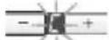
When the activated carbon filter reaches saturation point, an acoustic signal is sounded for 10 seconds after the fan has switched off, and a symbol appears in the display. The activated carbon filter should be replaced straight away.
Removing the filter:
Warning: The halogen bulbs must be switched off and cool.
- Remove the metal filters.
- Press in the lug at the front and remove the activated carbon filter.

- Insert the metal grease filters.
Replacing the activated carbon filter:
A replacement filter can be obtained from any authorized dealer (see optional accessories).
Use original filters only.
By doing so you will obtain maximum performance from your extractor hood.
Disposing of the old activated carbon filter:
There are no pollutants in the activated carbon filters. They can therefore be disposed of as part of your normal domestic refuse.
Cleaning and care
Disconnect the extractor hood from the electricity supply by pulling out the mains plug or switching it off at the fuse box.
At the same time as you clean the grease filters, clean off any grease from all accessible parts of the housing. This significantly reduces the fire hazard and ensures that the extractor hood performs as effectively as possible.
Use a hot detergent solution or a mild window cleaner to clean the canopy of the extractor hood.
Do not scrape off any dirt that has dried on but loosen it up with a damp cloth.
Do not use abrasive cleaning agents or sponges that could cause scratches.
Note: Do not use alcohol (spirit) on plastic parts, otherwise the surface may become matt in appearance.
Caution: Ensure that the kitchen is adequately ventilated. Avoid naked flames!
Clean the operating buttons with a mild soapy solution and a soft, damp cloth only. Do not use stainless-steel cleaner to clean the operating buttons.
Stainless steel surfaces:
Use a mild non-abrasive stainless steel cleaner.
Clean the surface in the same direction as it has been ground and polished.
Do not use any of the following to clean stainless steel surfaces: abrasive sponges, cleaning agents containing sand, soda, acid or chloride!
Aluminium, painted and plastic surfaces:
Use a soft, non-linting window cloth or micro-fibre cloth.
Do not use dry cloths.
Use a mild window cleaning agent.
☐ Do not use aggressive, acidic or caustic cleaners.
☐ Do not use abrasive agents.
Replacing the light bulbs
- Switch off the extractor hood and pull out the mains plug or switch off the electricity supply at the fuse box.
When switched on, the halogen bulbs become very hot. Even for some time after the bulbs have been switched off there is still a risk of burns.
- Remove the bulb ring with a screwdriver or similar tool.

- Replace the halogen light bulb (conventional halogen bulb, 12 Volt, max. 20 Watt, G4 cap). Caution: Refer for plug-in lampholder. Take hold of the bulb with a clean cloth.

- Re-insert the bulb ring.
- Plug the appliance into the mains or switch it on at the fuse box.
Note: If the light does not function, check that the bulbs have been inserted correctly.
Setting the saturation indicator
If it becomes necessary to change the operating mode (exhaust-air/recirculating mode), the saturation indicator for the filters must also be altered (see Installation Instructions).
If you encounter a problem
If an or appears in the display:
☐ See "Filters and maintenance" Section. If is not possible to operate the extractor hood: ☐ Disconnect the extractor hood from the mains electricity supply by pulling out the plug or switching it off at the main fuse box. Wait for approx. 1 minute and then switch it on again.
If you have any questions or if a fault occurs, please call Customer Service.
(See list of Customer Service representatives).
When you call, please quote the following:
E-Nr.
FD
Enter the relevant numbers into the box above. The E-Nr. (product no.) and FD (production date) are shown on the nameplate which can be seen inside the extractor hood after the filter frame has been detached.
Important information
⚠️ Old appliances are not worthless rubbish. If they are disposed of in an environment-friendly manner, valuable raw materials can be recovered for use again. Before you dispose of an old appliance, make sure that it has been rendered inoperative.
⚠️ Your new appliance was protected on its way to you by the packaging. None of the materials cause pollution to the environment and all can be recycled for use again. Please help to protect the environment and dispose of the packaging in an environment-friendly manner.
You can obtain information about the best method of disposing of old appliances and packaging from your dealer or local municipal council.
⚠ The extractor hood can be used in either exhaust-air or recirculating mode.
⚠️ Always mount the extractor hood over the centre of the hob.
⚠️ Minimum distance between electric hob and bottom edge of extractor hood: 550 mm, Fig. 1.
Additional notes concerning gas cookers:
When installing gas hotplates, comply with the relevant national statutory regulations (e.g. in Germany: Technische Regeln Gasinstallation TRGI).
The relevant regulations and installation notes provided by the manufacturer of the gas cooker must be observed in all cases.
The extractor hood may be installed next to only one full-height cupboard or high wall. Gap to be at least 50 mm.
During installation observe a minimum distance of 650 mm above the gas hotplates. Fig. 1.
Gas hotplates may only be used when cooking utensils have been placed on them.
Gas hobs / gas cookers:
The heat load of all the hotplates which is produced during operation must not exceed 8.0 kW, irrespective of the installed nominal output.
Exception: The hotplates may be operated briefly (max. 15 minutes) at a heat load up to 11.3 kW if at least fan setting 2 has been permanently switched on. (Otherwise, there is a risk of burns if the housing surfaces are touched).
Solid-fuel cookers
The maximum nominal heat loads and the minimum distance are the same as for gas cookers.
Installation of the extractor hood over a solid-fuel burner which could constitute a potential fire hazard (e.g. due to flying sparks) is only permitted if the burner is equipped with an enclosed, non-removable cover and all country-specific regulations are observed. This restriction does not apply to gas cookers and gas hobs.
The smaller the gap between extractor hood and hob, the greater the likelihood that rising steam will cause condensation to form on the hood.
Prior to installation
Exhaust-air mode
The exhaust air is discharged upwards through a ventilation shaft or directly through the outside wall into the open.
Exhaust air should neither be directed into a smoke or exhaust flue that is currently used for other purposes, nor into a shaft that is used for ventilating rooms in which stoves or fireplaces are also located.
Exhaust air may be discharged in accordance with official and statutory regulations only (e.g. national building regulations).
Local authority regulations must be observed when discharging air into smoke or exhaust flues that are not otherwise in use.
When the extractor hood is operated in exhaust-air mode simultaneously with a different burner which also makes use of the same chimney (such as gas, oil or coal-fired heaters, continuous-flow heaters, hot-water boilers) care must be taken to ensure that there is an adequate supply of fresh air which will be needed by the burner for combustion.
Safe operation is possible provided that the underpressure in the room where the burner is installed does not exceed 4 Pa (0.04 mbar).

This can be achieved if combustion air can flow through non-lockable openings, e.g. in doors, windows and via the air-intake/exhaust-air wall box or by other technical measures, such as reciprocal interlocking, etc.
If the air intake is inadequate, there is a risk of poisoning from combustion gases which are drawn back into the room.
An air-intake/exhaust-air wall box by itself is no guarantee that the limiting value will not be exceeded.
Note: When assessing the overall requirement, the combined ventilation system for the entire household must be taken into consideration. This rule does not apply to the use of cooking appliances, such as hobs and ovens.
Unrestricted operation is possible if the extractor hood is used in recirculating mode – with activated carbon filter.
Prior to installation
For optimum extractor hood efficiency:
☐ Short, smooth air exhaust pipe. ☐ As few bends in the pipe as possible. ☐ Diameter of pipe to be as large as possible and no tight bends in pipe. If long, rough exhaust-air pipes, many pipe bends or smaller pipe diameters are used, the air extraction rate will no longer be at an optimum level and there will be an increase in noise.
Round pipes:
We recommend Internal diameter: 150 mm (at least 120 mm).
☐ Flat ducts must have an internal cross-section that equates to that of round pipes.
There should be no sharp bends.
∅ 120 mm approx. 113 cm
∅ 150 mm approx. 177 cm
☐ If pipes have different diameters: Insert sealing strip.
☐ For exhaust-air mode, ensure that there is an adequate supply of fresh air.
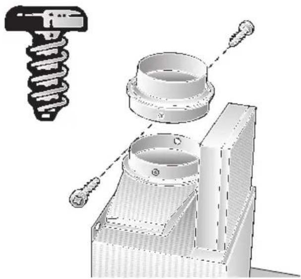
Connecting a φ 150 mm exhaust-air pipe:
□ Mount the pipe directly onto the air outlet on the hood.
Connecting a φ 120 mm exhaust-air pipe:
☐ Screw a reducing adapter onto the air outlet on the hood and then connect the exhaust-air pipe.
Circulating-air mode
☐ With activated carbon filter if exhaust-air mode is not possible.
⚠ The complete installation set can be obtained from specialist outlets. The corresponding accessory numbers can be found at the end of these operating instructions.


Prior to installation
Preparing the wall
☐ The wall must be flat and perpendicular. ☐ Ensure that the wall is capable of providing a firm hold for mounting screws and plugs.
Weight in kg:
| Exhaust air Recirculating air | |
| 22,521,5 | |
We reserve the right to make construction changes as part of technical development.
Switching from exhaust-air mode to recirculating mode
Changing the electronic control system to recirculating mode:
The standard factory setting is for operation in exhaust-air mode. To change the mode, the extractor hood must be connected and switched off.


- Press and hold the 0 button.
- While ☐ is displayed, press the ➕ button until └ is displayed. When this has happened, release the buttons. ☐ goes out shortly afterwards. The electronic control system will then have been set to recirculating mode. By repeating steps 1 and 2, you can change the electronic control system back to exhaust-air mode (= in display).
Electrical connection
WARNING: THIS APPLIANCE MUST BE EARTHED
IMPORTANT: Fitting a Different Plug:
The wires in the mains lead are colored in accordance with the following code:
Green and Yellow – Earth
Blue - Neutral
Brown – Live
If you fit your own plug, the colors of these wires may not correspond with the identifying marks on the plug terminals.
This is what you have to do:
- Connect the green and yellow (Earth) wire to the terminal in the plug marked 'E' or with the symbol (≡), or colored green or green and yellow.
- Connect the blue (Neutral) wire to the terminal in the plug marked 'N' or colored black.
- Connect the brown (Live) wire to the terminal marked 'L', or colored red.
The extractor hood should only be connected to an earthed socket that has been installed according to relevant regulations.
If possible, site the earthed socket directly behind the chimney panelling.
Electrical data:
Are to be found on the name plate inside the appliance after removal of the filter frame.
⚠️ Before undertaking any repairs, always disconnect the extractor hood from the electricity supply.
Length of the connecting cable: 1.30 m. If it is necessary to wire the extractor hood directly into the mains:
The extractor hood should only be connected to the electricity supply by a properly qualified electrician.
A separator must be installed in the household circuit. A suitable separator is a switch that has a contact gap of more than 3 mm and interrupts all poles. Such devices include circuit breakers and contactors.
This extractor hood corresponds to EC regulations concerning RF interference suppression.
Installation
This extractor hood is intended to be mounted onto the kitchen wall.
- Remove the grease filter (refer to Operating Instructions).
- Draw a line on the wall from the ceiling to the lower edge of the hood at the centre of the location where the hood is going to be mounted.
- Use the template to mark the points on the wall where the screws will be mounted. In order to make it easier to hook the hood onto the screws, draw the outline of the area where the hood will be attached.
⚠ Ensure that the minimum distance between the hob and the extractor hood is maintained – 550 mm for an electric hob and 650 mm for a gas hob. The bottom edge of the template corresponds to the lower edge of the extractor hood (glass screen).
- Drill 3 x ∅ 8 mm holes for the extractor hood and 2 x ∅ 8 mm holes for the chimney panelling. Insert plugs into the holes so that they are flush with the wall.


Note: Take into account any special accessories that are going to be fitted.
- Screw on the upper and the two lower fixing brackets.

- Attach the extractor hood. Adjust the height and align horizontally with the adjusting screws.

⚠ The glass screen must not touch the wall.
Installation
- Screw in the lower bolt (hex bolt).

⚠️ If any pressure is exerted on the glass screen when tightening the screws it could lead to glass breakage.
- Stick protective film over the holes of the 2 lower mounting bolts in the protective grid.
- Connect up the air outlet pipe.
- Connect the hood to the electricity supply.
- Remove the protective film from the two flue ducts.
⚠ Avoid damage to the sensitive surface.
- Insert the upper flue duct (slots downwards) into the lower flue duct.

⚠️ Protect the cover panels from scratches, for example by laying the template used for marking the wall over the top edge of the lower section.
- Insert the complete flue duct at an angle into the glass shield and swivel backwards.
- Carefully pull the upper flue duct upwards and screw the sides to the fixing bracket with 2 screws.

- Insert the grease filter (refer to Operating Instructions).
Operating instructions:
Intensive ventilation:

Before installation
Wall preparation
Note: plug fitting.

Before mounting
- Replace the halogen lamp (commercial halogen lamp, 12 Volt, max. 20 Watt, G4 base).

Before mounting

Before mounting
- Replace the grease filter.
- Replace the halogen lamp (commercial halogen lamp, 12 Volt, max. 20 Watt, G4 base).

Before mounting
Grease filter

Before mounting
- Replace the halogen bulb (standard halogen bulb, 12 volt, max. 20 watt, G4 socket). Note: Socket holder. Use a clean cloth when handling the bulb.

Recirculation mode

Before mounting

Before mounting
- Press the tab in from the front.
- Insert the grease filters (see Removing and inserting the metal grease filters).
- Switch off the alarm £.
□ Press the 0 button.
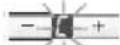
Suction stop:
- Insert the grease filters.
- Replace the halogen lamp (standard halogen lamp, 12 V, max. 12 W, socket G4).
Air recirculation

Before installation
- DKE 995 P
- HOUSEHOLD APPLIANCES
- RECIRCULATION MODE
- BEFORE INSTALLATION
- INSTRUCTIONS FOR USE
- APPLIANCE DESCRIPTION
- OPERATING MODES
- EXHAUST-AIR MODE
- IF THE AIR INTAKE IS INADEQUATE, THERE IS A RISK OF POISONING FROM COMBUSTION GASES WHICH ARE DRAWN BACK INTO THE ROOM
- CIRCULATING-AIR MODE
- BEFORE USING FOR THE FIRST TIME
- IMPORTANT NOTES
- GAS HOBS / GAS COOKERS
- IMPORTANT
- OPERATING PROCEDURE
- ACOUSTIC SIGNAL
- SWITCHING OFF THE ACOUSTIC SIGNAL
- SWITCHING ON THE ACOUSTIC SIGNAL
- SETTING THE REQUIRED FAN SPEED
- INTENSIVE SETTING
- FAN FOLLOW-ON
- LIGHTING
- SWITCHING ON THE LIGHT AUTOMATICALLY, E.G. VIA A TIMER
- SWITCHING ON
- SWITCHING OFF
- FILTERS AND MAINTENANCE
- GREASE FILTERS
- METAL FILTERS ARE USED TO TRAP THE GREASY ELEMENT OF THE VAPOURS THAT DEVELOP DURING COOKING
- CAUTION
- SATURATION INDICATOR
- CLEANING THE METAL GREASE FILTERS
- REMOVING AND INSERTING THE METAL GREASE FILTERS
- ACTIVATED CARBON FILTER
- INSERTING THE FILTER
- REMOVING THE FILTER
- REPLACING THE ACTIVATED CARBON FILTER
- DISPOSING OF THE OLD ACTIVATED CARBON FILTER
- CLEANING AND CARE
- DISCONNECT THE EXTRACTOR HOOD FROM THE ELECTRICITY SUPPLY BY PULLING OUT THE MAINS PLUG OR SWITCHING IT OFF AT THE FUSE BOX
- STAINLESS STEEL SURFACES
- ALUMINIUM, PAINTED AND PLASTIC SURFACES
- REPLACING THE LIGHT BULBS
- SETTING THE SATURATION INDICATOR
- IF YOU ENCOUNTER A PROBLEM
- IMPORTANT INFORMATION
- ADDITIONAL NOTES CONCERNING GAS COOKERS
- SOLID-FUEL COOKERS
- PRIOR TO INSTALLATION
- EXHAUST AIR MAY BE DISCHARGED IN ACCORDANCE WITH OFFICIAL AND STATUTORY REGULATIONS ONLY (E.G. NATIONAL BUILDING REGULATIONS)
- FOR OPTIMUM EXTRACTOR HOOD EFFICIENCY
- CONNECTING A Φ 150 MM EXHAUST-AIR PIPE
- CONNECTING A Φ 120 MM EXHAUST-AIR PIPE
- PREPARING THE WALL
- SWITCHING FROM EXHAUST-AIR MODE TO RECIRCULATING MODE
- CHANGING THE ELECTRONIC CONTROL SYSTEM TO RECIRCULATING MODE
- ELECTRICAL CONNECTION
- WARNING: THIS APPLIANCE MUST BE EARTHED
- IMPORTANT: FITTING A DIFFERENT PLUG
- ELECTRICAL DATA
- LENGTH OF THE CONNECTING CABLE: 1.30 M. IF IT IS NECESSARY TO WIRE THE EXTRACTOR HOOD DIRECTLY INTO THE MAINS
- INSTALLATION
- OPERATING INSTRUCTIONS
- INTENSIVE VENTILATION
- WALL PREPARATION
- BEFORE MOUNTING
- GREASE FILTER
- SUCTION STOP
- AIR RECIRCULATION
Brand : BOSCH
Model : DKE995P
Category : Range hood