XC902GHDC.3 - Cooker Hotpoint Ariston - Free user manual and instructions
Find the device manual for free XC902GHDC.3 Hotpoint Ariston in PDF.


| Product type | Gas cooker with electric oven |
| Brand | Hotpoint Ariston |
| Model | XC902GHDC.3 |
| Width | 90 cm |
| Depth | 60 cm |
| Height | 85-90 cm (adjustable) |
| Net weight | Approximately 70 kg |
| Gas supply | Natural gas (G20) or butane/propane (G30) |
| Electrical supply | 220-240 V / 50-60 Hz |
| Maximum electrical power | Approximately 3.5 kW |
| Number of gas burners | 5 burners (including one triple crown) |
| Oven type | Multifunction electric oven (fan-assisted, grill, traditional heat) |
| Oven capacity | Approximately 75 litres |
| Oven cleaning | By pyrolysis (self-cleaning) |
| Cooking functions | Fan-assisted, grill, bottom heat, top heat, defrost, pizza |
| Safety | Burner anti-overflow device, automatic oven shut-off, child safety lock |
| Oven door | Cool door with double glazing |
| Oven lighting | Interior lamp |
| Included accessories | Grid, drip tray, cooking probe (depending on model) |
| Maintenance | Clean enameled surfaces with a damp cloth and mild detergent |
| Spare parts | Available from Hotpoint Ariston customer service |
| Repairability | Repairability index above 7/10 |
| General information | User manual available for free download |
Frequently Asked Questions - XC902GHDC.3 Hotpoint Ariston
User questions about XC902GHDC.3 Hotpoint Ariston
0 question about this device. Answer the ones you know or ask your own.
Ask a new question about this device
Download the instructions for your Cooker in PDF format for free! Find your manual XC902GHDC.3 - Hotpoint Ariston and take your electronic device back in hand. On this page are published all the documents necessary for the use of your device. XC902GHDC.3 by Hotpoint Ariston.
USER MANUAL XC902GHDC.3 Hotpoint Ariston
Instructions for use and installation
FORNO MULTIFUNZIONE
fig 4
fig.7


Fig. C Fig. D
Congratulations on choosing an Ariston appliance, which you will find is dependable and easy to use. We recommend that you read this manual for best performance and to extend the life of your appliance. Thank you.
THESE INSTRUCTIONS ARE ONLY VALID FOR THE COUNTRIES OF DESTINATION WHOSE SYMBOLS ARE SHOWN IN THE BOOKLET AND THE APPLIANCE RATING PLATE.
-
This appliance has been designed for private, non-professional use in normal dwellings.
-
Read the recommendations in this instruction booklet carefully, as they give important advice regarding safe installation, use and maintenance. Keep this booklet in a safe place for further reference when required.
-
Oven accessories which may come into contact with food are made of materials which comply with the contents of EEC Regulation 89/109 of 21.12.88 and national regulations in force.
-
After having removed the packaging, check that the appliance is intact. If in doubt, do not use the appliance and contact professionally qualified personnel.
-
Some parts are covered with a removable scratch-proof film. Before using the appliance the film should be removed and the underlying part cleaned with a cloth and a non-abrasive household cleaning product. When switching on for the first time, it is advisable to heat the empty oven at maximum temperature for about 30 minutes to eliminate any residue from manufacture.
-
All installation and adjustment operations should be carried out by qualified technicians in accordance with current regulations. Specific indications are given in the "instructions for the installer" paragraph.
-
Before connecting the appliance, make sure that the data on the rating plate (situated on the rear part of the appliance and on the last page of the instruction booklet) correspond to those of the mains electricity and gas supplies.
-
During operation, the oven glass door and adjacent parts of the appliance become hot. Make sure, therefore, that children do not touch the appliance.
-
Check that the capacity of the electrical system and the power outlets are suitable for the maximum power of the appliance, indicated on the rating plate. If in doubt, consult a professionally qualified technician.
-
Periodically check the condition of the gas connection pipe and have it replaced by a qualified technician as soon as it shows any signs of wear or anomaly.
-
Under no circumstances should the user replace the power supply cable or the gas connection pipe of this appliance. In the event of damage or the necessity for replacement, only contact an authorised service centre.
-
Do not leave the appliance plugged in if it is not in use. Switch off the main switch and gas supply when you are not using the cooker.
-
The burners and the cast-iron pan supports remain hot for a long time after use. Take care not to touch them.
-
To avoid accidental spillage do not use cookware with uneven or deformed bottoms on the burners.
-
Never use flammable liquids such as alcohol or gasoline, etc. near the appliance when it is in use.
-
If the cooker is placed on a pedestal, take the necessary precautions to prevent the same from sliding off the pedestal itself.
- Do not use steam cleaners to clean your oven

Disposal of old electrical appliances
The European Directive 2002/96/EC on Waste Electrical and Electronic Equipment (WEEE), requires that old household electrical appliances must not be disposed of in the normal unsorted municipal waste stream. Old appliances must be collected separately in order to optimise the recovery and recycling of the materials they contain and reduce the impact on human health and the environment. The crossed out "wheeled bin" symbol on the product reminds you of your obligation, that when you dispose of the appliance it must be separately collected.
Consumers may take their old appliance to public waste collection areas, other communal collection areas, or if national legislation allows return it to a retailer when purchasing a similar new product.
All major household appliance manufacturers are active in the creation of systems to manage the collection and disposal of old appliances.

This appliance conforms with the following European Economic Community directives:
- 73/23/EEC of 19/02/73 (Low Voltage) and subsequent modifications;
- 89/336/EEC of 03/05/89 (Electromagnetic Compatibility) and subsequent modifications;
- 90/396/EEC of 29/06/90 (Gas) and subsequent modifications;
- 93/68/EEC of 22/07/93 and subsequent modifications.
COOKER DESCRIPTION

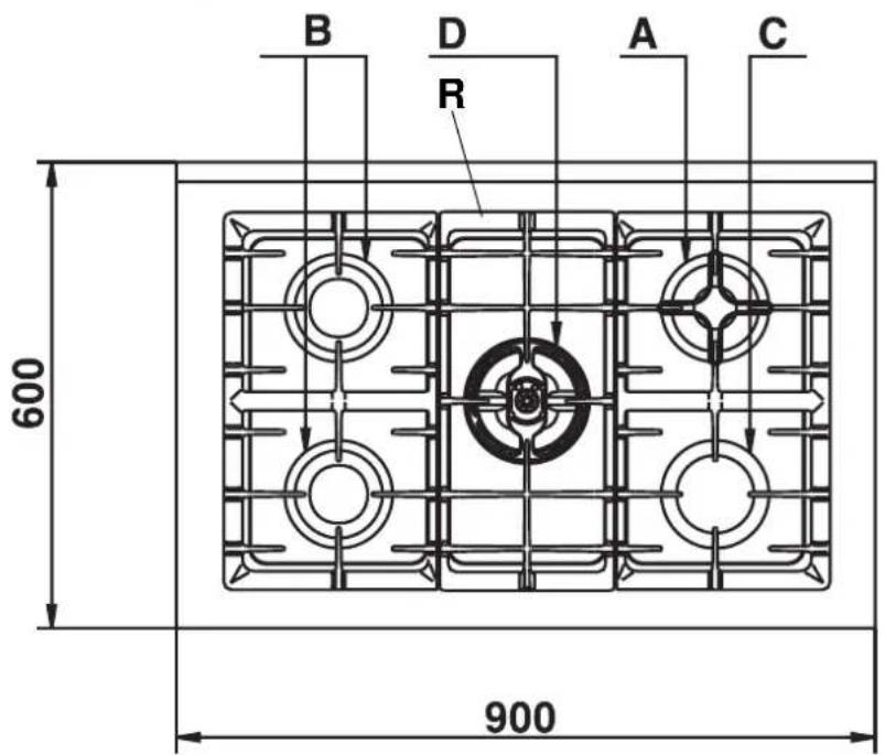
A Auxiliary gas burner
B Semi-rapid gas burner
C Rapid gas burner
D DCDR gas burner
R Support Grid for Cookware
M Control Knobs for Gas Burners
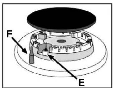
E Ignitor for Gas Burners
F Safety Device - Activates if the flame accidentally goes out (spills, drafts, etc.), interrupting the delivery of gas to the burner.
T Minute minder
S Electric oven operation indicator light
G Electric oven selector knob (cooking function selection)
H Electric oven thermostat knob (temperature selection)
INSTRUCTIONS FOR USE
HOB OPERATION
The burners are fitted with automatic ignition and a thermocouple safety device, which automatically cuts off the gas from the burner in a few seconds if the flame accidentally goes out during operation.
The burners differ in size and power. Choose the most appropriate one for the diameter of the cookware being used.
Each burner can be regulated with the corresponding control knob "M" by using one of the following settings:
| Off | |
| High flame | |
| Low flame |
The symbols near the knobs show the position of the relative burner on the hob.
Toignite a burner, proceed as follows:
- turn the relative knob counter-clockwise until the pointer is on the high-flame symbol;
- press the knob down fully and activate the automatic gas ignition marked with the symbol ☆
- keep the knob pressed down for about 10 seconds with the flame lit to allow the safety thermocouple to be heated;
- release the knob, checking that the flame is stable. If it is not, repeat the operation.
For minimum power, turn the knob towards the low flame symbol. Intermediate positions are possible by simply putting the knob anywhere between the high and the low flame symbol.
To turn off the burner, turn the knob clockwise to the off position "●".
Important:
- Do not activate the automatic ignition device for more than 15 consecutive seconds.
- Difficulty in ignition is sometimes due to air inside the gas duct.
- If a burner flame accidentally goes out, the gas continues to exit for a few moments before the safety device activates. Turn the control knob to the off position and do not attempt ignition again for at least 1 minute, thereby letting the gas disperse, which could otherwise be a danger.
- When the appliance is not in operation, check that the knobs are in the off position "●". The main gas supply cut-off cock should also be closed.
Using the burners
To obtain maximum efficiency from the burners, it is advisable to only use pans with a diameter suitable for the burner being used, so that the flame does not extend beyond the pan base (see following table). When a liquid starts boiling, it is advisable to turn the flame down just enough to keep the liquid simmering.
The hob is fitted with two pan reducing supports, which should only be used on the auxiliary burner "A"(fig.1a) and on the Double Flame "D" (DC-DR internal)(fig.1b).
| Burner ø Pan Diameter (cm) | |
| A.Auxillary | 6 – 14 |
| B.Semi-rapid | 15 – 20 |
| C.Rapid | 21 – 26 |
| I.Double ring DC-DR (inner) | 10 - 14 |
| I.Double ring DC-DR (outer) | 24 - 26 |

fig.1a
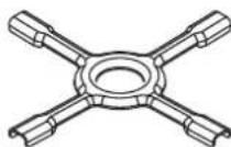
fig.1b
The "separate double flame" burner
This burner consists of two concentric burners which can operate either together or separately.
Use of the double flame on the maximum setting gives a very high power which reduces cooking times with respect to conventional burners.
Moreover the double flame crown provides a more uniform distribution of heat on the bottom of the pan, when using both burners on minimum.
Pots and pans of all sizes can be used. In the case of the smaller pots and pans we recommend the use of only the internal burner.
There is a separate control knob for each of the "separate double flame" burners.
The knob marked by the symbol □ operates the external burner;
The knob marked by the symbol □ operates the internal burner.
To ensure that the double-flame burner is used to its full potential, never set the inside ring to minimum and the outside ring to maximum at the same time.
To turn on one of the rings, press the relative knob in all the way and turn it anti-clockwise to the high setting △. The burner is fitted with an electronic igniter that automatically starts when the knob is pressed in.
Since the burner is equipped with a safety device "F", after lighting the burner keep the knob pressed in for about 6 seconds to allow the device which keeps the flame lit automatically to heat up.
To obtain the best results with the cooktop, several fundamental rules should be followed while cooking or preparing food. Use cookware with a flat bottom to make certain that the pot sets properly on the cooking area.

THE "MAXIOVEN"
MULTI-FUNCTION OVEN
The oven offers nine combinations of heating elements; so the most suitable combination may therefore be chosen for each dish, with convincing results.
By turning the selector knob "G" marked with the symbol different cooking modes are obtained, as shown in the following table:
| Symbol | Function Power | |
| 0 | 0) Off | - |
 | 1) Top + Bottom heating elements | 2350 W |
| [OASD] | 2) Bottom heating element | 1300 W |
| [BACS] | 3) Top heating element | 1050 W |
 | 4) Grill heating element | 2000 W |
| [W6AS] | 5) Maxigrill (Top + Grill heating elements) | 3050 W |
 | 6) Maxigrill (Top + Grill heating elements) + fan | 3100 W |
 | 7) Bottom heating element + Fan | 1350W |
| [ZY28] | 8) Rear round heating element + Fan | 2850 W |
| [DDHS] | 9) Fast defrosting | 50 W |
After having selected the heat source, put the thermostat knob "H" (marked with the symbol 4) onto the temperature required.
- For traditional cooking (roasts, biscuits, etc.) in conventional mode use the mode (hot above + below).
Only put the food to be cooked into the oven when it has reached the selected temperature and preferably use just one shelf for cooking.
To provide heat only to the bottom or the top part of the dishes, turn the selector to the position (hot below) or
hot below + fan) or (hot above);
- With this (fan assisted) mode heat is transmitted to the food through pre-heated air made to circulate inside the oven by a fan. The oven heats up very quickly so the food to be cooked may be put into the oven as soon as it is switched on. Cooking is also possible simultaneously on two shelves.
- The "fast defrosting" function ✿ uses no heating elements, just the oven light and the fan.
- Grill operation: a high heat output is used for grilling, so that the surface of the food is immediately browned; this is particularly indicated for meats which should remain tender on the inside.
To grill, turn the selector knob "H" to one of these positions:

(grill),

axigrill),

axigrill + fan)
During grilling, do not set the thermostat knob to above 200°C and keep the oven door closed.
Oven light
The oven light comes on automatically when the selector knob is turned to any of its positions.
Indicator light "S"
It indicates that the oven is heating up. When the light goes out, the required temperature has been reached inside the oven.
When the light alternately comes on and goes out, it means that the thermostat is working properly to maintain the oven temperature.
Spit - Rotisserie
Insert the meat to be cooked along the length of the spit rod, securing it with the special adjustable forks (fig. 2a). Introduce the supports "A" and "B" (fig. 2b) into the holes in the drip tray "E", rest the rod groove on the seat "C" and insert the oven rack into the lowest guide of the oven; now insert the spit rod into the relative hole, moving the groove forward into seat "D". Start the rotisserie by turning the selector knob to one of the following positions: (grill),

(maxigrill) o

axigrill with fan).

Fig. 2a

Fig. 2b
HOW TO KEEP YOUR OVEN IN SHAPE
Before cleaning your oven, or performing maintenance, disconnect it from the power supply.
To extend the life of your oven, it must be cleaned frequently, keeping in mind that:
- The self-cleaning panels (if present) and the enameled parts should be washed with warm water - abrasive powders and corrosive substances should be avoided;
- The inside of the oven should be cleaned immediately after use with warm water and soap; the soap should be rinsed away and the interior dried thoroughly;
- Stainless steel can be stained if it remains in contact with aggressive detergents (containing phosphorus) or water with a high lime content. We recommend that you rinse these parts thoroughly and dry them well after cleaning. It is also a good idea to dry any water spills;
- Never line the bottom of the oven with aluminium foil because the buildup of heat will not only impede the cooking process, but could also damage the enamel.
Replacing the Lamp in the Oven
- Cutoff the supply of power to the oven by turning off the omni-polar switch connecting it to the mains, or by removing the plug if it is accessible;
- Unscrew the glass cover attached to the lamp holder;
- Unscrew the lamp and replace it with another high-temperature lamp (300°C) with the following characteristics:
- Voltage: 230/240 V
- Wattage: 15W
- Socket: E14
- Remount the glass cover and reconnect the appliance to the power supply.
Disassembling/assembling the oven door
To make it easier to clean the inside of your oven, the oven door can be removed, by proceeding as follows (fig. 3-4):
- Open the door completely and lift the 2 levers "B" (fig. 3);
- Now, shutting the door slightly, you can lift it out by pulling out the hooks "A" as shown in figure 4.
To reassemble the door:
- With the door in a vertical position, insert the two hooks "A" into the slots;
- Ensure that seat "D" is hooked perfectly onto the edge of the slot (move the oven door backwards and forward slightly);
- Keep the oven door open fully, unhook the 2 levers "B" downwards and then shut the door again.


fig 4
THE ELECTRONIC PROGRAMMER
The electronic programmer has the function of automatically switching on the oven (at the required time) and switching it off at the end of the set cooking time. The 4 figure luminous display showing the actual time and the programming times, also shows the current state of the oven by means of the following symbols:
Oven on
Minute minder 🔒
Automatic programme AUTO
Point • (this divides the hour from the minutes on the display)
All the functions may be programmed for a total of 23 h and 59 min. Maximum cooking time is 10 hours.
Adjusting the clock
(At installation, after power failures, clock in advance or behind).
Select manual mode by pressing key 📋 adjust the hour and minutes using the -and + keys.
Manual oven mode (Programming excluded)
Press the key 📋 and the oven is switched on, the AUTO symbol goes out and the 📋oven on) symbol comes on.
This operation erases any set programme.
Semi-automatic oven mode
1st example: start in manual cooking mode - programmed cooking time.
- Put the food to be cooked in the oven.
- Press the key (duration) and adjust the cooking time using the -and + keys: the oven switches on, the AUTO and (oven on) symbols light up.
- Turn the selector and the thermostat knobs onto the required function and temperature respectively.
- At the end of the set cooking time, the oven is automatically switched off, the symbol ☐(oven on) goes out and the AUTO symbol blinks; an acoustic signal sounds.
2nd example: start with manual cooking mode - end with programmed cooking mode.
- Put the food to be cooked in the oven.
- Press the key (end of cooking) and adjust the end of cooking time using the - and + keys: the oven switches on, the AUTO and symbols light up.
- Turn the selector and the thermostat knobs onto the required function and temperature respectively.
- At the end of cooking, the oven is automatically switched off, the symbol (oven on) goes out and the AUTO symbol blinks; an acoustic signal sounds.

Automatic oven mode (programmed cooking duration and end)
- Put the food to be cooked in the oven.
- Press the key (Duration) and adjust the cooking time using the - and + keys: the AUTO and (oven on) symbols light up (the oven switches on).
- Press the key (end of cooking) and adjust the end of cooking time using the - and + keys: the symbol goes out (the oven switches off).
- Turn the selector and the thermostat knobs onto the required function and temperature respectively.
- The programmer automatically sets the start of cooking time, which is shown by the symbol (woven on) coming on. When the cooking time has elapsed, the oven is automatically switched off, the (woven on) symbol goes out and the AUTO symbol blinks; an acoustic signal sounds.
Minute minder
Press the /key (minute minder) and set the time required using the - and + keys. An acoustic signal sounds at the end of the programme.
Buzzer
The buzzer emits a sound for 7 minutes after the end of the selected programme; it may be stopped by pressing any function key. It is possible to choose 3 different types of acoustic signal. By pressing the - key the actual signal tone appears. Now, within 7 seconds, every further press of the - key changes the signal tone.
Program control
Press the key for the remaining time to be displayed, and the key check the end of cooking time.
Erasing programs
Once a programme has been carried out, it is automatically erased; it can also be cancelled by pressing the key 📄 (manual).
PRACTICAL COOKING ADVICE
Preheating
If the oven must be preheated (generally this is the case when cooking leavened foods) the ☒ “ventilation” mode can be used to reach the desired temperature as quickly as possible in order to save on energy.
Once the food has been placed in the oven, the most appropriate cooking mode can then be selected.
Using the Grill
Use the “grill” it allows you to grill small portions like toasted sandwiches, hotdogs, etc., to perfection.
Position the food under the center of the grill because only the central part of the top heating element is turned on. Food placed in the corners will not cook properly.
The “Ventilated Grill” is extremely useful for grilling foods rapidly, as the distribution of heat makes it possible not only to brown the surface, but also to cook the bottom part.
This mode can also be used for browning foods at the end of the cooking process.
Important: always use the grill with the oven door closed. This will allow you both to attain excellent results and to save energy (10% circa).
For the best results when cooking on the grill, it is recommended to use the highest setting of the thermostat (200°C), which utilizes infrared rays. The grill should be placed on the higher racks (see the cooking chart). To catch fat and prevent smoke, place a dripping pan beneath the rack used for grilling.
When utilizing the grill, place the rack at the lower levels (see cooking table). To catch grease or fat and prevent smoke, place a dripping-pan at the bottom rack level.
Baking Pastries
When baking pastries, always place them in the oven after it has been preheated. Make sure you wait until the oven has been preheated thoroughly (the red "S" light will turn off). Do not open the door while the pastry is cooking in order to prevent it from dropping.
Batters must not be too runny, as this will result in prolonged cooking times. In general:
| Pastry is too dry |
| Increase the temperature by 10°C and reduce the cooking time. |
| Pastry dropped |
| Use less liquid or lower the temperature by 10°C. |
| Pastry is too dark on top |
| Place it on a lower rack, lower the temperature, and increase the cooking time. |
| Cooked well on the inside but sticky on the outside |
| Use less liquid, lower the temperature, and increase the cooking time. |
| The pastry sticks to the pan |
| Grease the pan well and sprinkle it with a dusting of flour. |
| I used more than one level and they are not all at the same cooking point |
| Use a lower temperature setting. It is not necessary to remove the food from all the racks at the same time. |
Cooking Pizza
For best results when cooking pizza use the "ventilation
mode"
- Preheat the oven for at least 10 minutes;
- Use a light aluminum pizza pan, placing it on the broiler supplied with the oven. If the dripping-pan is used, this will extend the cooking time, making it difficult to get a crispy crust;
- Do not open the oven door frequently while the pizza is cooking;
- If the pizza has a lot of toppings (three of four), it is recommended that the mozzarella cheese be placed on top halfway through the cooking process;
Cooking Fish and Meat
Meat must weigh at least 1 Kg in order to prevent it from drying out. When cooking white meat, fowl and fish, use low temperature settings ( 150° C- 200° C). For red meat that should be well done on the outside while tender and juicy in the inside, it is a good idea to start with a high temperature setting ( 200° C- 220° C) for a short time, then turn the oven down afterwards. In general, the larger the roast, the lower the temperature setting. Place the meat on the centre of the rack and place the dripping pan beneath it to catch the fat.
Make sure that the rack is inserted so that it is in the centre of the oven. If you would like to increase the amount of heat from below, use the low rack heights. For savory roasts (especially duck and wild game), dress the meat with lard or bacon on the top.
COOKING TIPS
Cooking times may change according to the nature of the foods, their homogeneity and their volume. When cooking a certain food for the first time, it is advisable to choose the lowest values in the cooking time range given in the table and then increase them if necessary.
CONVENTIONAL OVEN COOKING
| Type of dish Temperature °C | Cooking time (minutes) | Type of dish Temperature °C Cooking time (hours) | |||
| Pastries and cakes | Meat | ||||
| Fruit pie | 130 | 60-70 | Turkey (4-8 kg) | 160 | 3-41/2 |
| Meringues | 130 | 30-40 | Goose (4-5 kg) | 160 | 4-41/2 |
| Sponge cake | 150 | 20-30 | Duck (2-4 kg) | 170 | 11/2-21/2 |
| Angel cake | 160 | 40-50 | Capon ( 21/2-3 kg) | 170 | 2-21/2 |
| Madeira cake | 160 | 40-50 | Braised beef ( 1-11/2 kg) | 160 | 3-31/2 |
| Chocolate cake | 170 | 30-40 | Leg of lamb | 160 | 1-11/2 |
| Flat sweet loaf | 170 | 40-50 | Roast hare (2 kg) | 160 | 1-11/2 |
| Puffs | 200 | 15-20 | Roast pheasant | 160 | 1-11/2 |
| Flaky pastry biscuits | 200 | 15-20 | Chicken ( 1-11/2 kg) | 170 | 1-11/2 |
| Mille feuilles | 200 | 15-20 | |||
| Short crust pastry | 200 | 15-20 | Fish | 200 | 15-25 minutes |
GRILLING
| Type of dish | Cooking time (minutes) | Position of shelf |
| Chops (0.5 kg) | 60 | 3rd guide rail |
| Saussages | 15 | 2nd guide rail |
| Grilled chicken (1 kg) | 60 | 1st guide rail |
| Veal on the spit (0.6 kg) | 60 | - |
| Chicken on the spit (1 kg) | 60 | - |
The 1 st guide rail is understood as being the lowest position.
FAN ASSISTED COOKING
| Type of dish | Guide rail no. from bottom | Quantity kg | Temperature °C | Time (minutes) |
| Cakes* With beaten mix, in mould* With beaten mix, without mouldShort pastry, flan baseShort pastry with wet fillingShort pastry with dry filling* With natural leavened mixSmall cakes | 1-31-3-41-3-41-31-3-41-31-3 | 110.51.51110.5 | 175175175175175175160 | 60503070455030 |
| MeatRoasts under the grillVealBeefEnglish roast beefPorkChickenRoasts on a trayVealBeefPorkChickenTurkey slicesDuckCasserolesBeef casseroleVeal casserole | 222222 | 1111-1.5 | 180180220180200 | 6070507070 |
| 1-31-31-31-31-3 | 111-1.51.51-1.5 | 160160160180180180 | 80909090120120 | |
| 11 | 11 | 175175 | 120110 | |
| FishFillets, steaks, cod, hake, soleMackerel, turbot, salmonOysters | 1-31.31-3 | 11 | 180180180 | 304520 |
| TimbalesBaked pasta dishVegetable pudding* Sweet and savoury soufflés* Pizzas and savoury rollsToasted sandwiches | 1-31-31-31-31-3-41-3-4 | 220.750.50.5 | 185185180200190 | 6050503015 |
| DefrostingReady-to-eat mealsMeatMeatMeat | 1-31-31-31-3 | 10.50.751 | 200505050 | 455070110 |
Notes:
1) Cooking times do not include oven pre-heating, except for those marked with an asterisk
2) The indication given in the table for the guide rails is the one that should preferably be used in the event of cooking on more than one level.
3) The indicated times refer to cooking on one shelf only; for cooking on more than one level, increase the time by 5 ÷ 10 min.
4) For roast beef, veal, pork and turkey, on the bone or rolled, increase the times by 20 min.
INSTALLATION
The following instructions are provided for qualified installers so that they may accomplish installation, adjustment and technical maintenance operations correctly and in compliance with current regulations and standards.
Important: the appliance should be disconnected from the mains electricity supply before any adjustment, maintenance, etc. is carried out. Maximum caution should be used should it be necessary to keep the appliance connected to the electricity supply.
The cookers have the following technical specifications:
Category: II 2H3+ Class: 1
The dimensions of the appliance are given in the figure on page 2. For trouble-free operation of appliances installed in housing units, the minimum distances shown in fig.5 should be observed. Adjacent surfaces and the wall at the rear should also be able to withstand an overheating temperature of 65 °C.
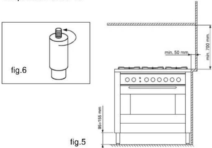
Prior to installing the cooker, 95 ÷ 155 mm high supporting feet (provided) should be fitted into the holes to be found in the bottom of the cooker (fig.6). These feet are screw-adjustable and whenever necessary should be used to make sure the cooker stands level.
Positioning
This appliance may only be installed and operated in permanently ventilated rooms in compliance with current standards. The following requirements must be observed:
- The appliance must discharge combustion products into a special hood, which must be connected to a chimney, flue pipe or directly to the outside (fig.7).
- If it is impossible to fit a hood, the use of an electric fan is permitted, either installed on a window or on an external wall, which must be switched on at the same time as the appliance.
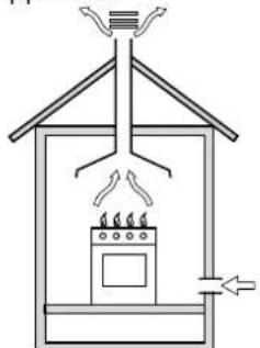
fig.7
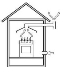
In a chimney stack or branched flue Directly to the outside (exclusively for cooking appliances)
Kitchen ventilation
The air flow into the room where the appliance is installed must equal the quantity of air that is required for regular combustion of the gas and for ventilating the same room. Air must be taken in naturally through permanent apertures made in the outside walls of the room or through single or branching collective ventilation ducts in compliance with current standards and regulations. The air must be taken directly from the outside, from an area far from sources of pollution. The ventilation aperture must have the following characteristics (fig.8A):
- total free cross section of passage of at least 6cm2 for every kW of rated heating capacity of the appliance, with a minimum of 100cm2 (the heating capacity is indicated on the rating plate);
- it must be made in such a way that the aperture, both on the inside and outside of the wall, cannot be obstructed;
- it must be protected, e.g. with grates, wire mesh, etc. in such a way that the above-mentioned free section is not reduced;
- it must be situated as near to floor level as possible.
Detail A Adjacent Room to be
room ventilated
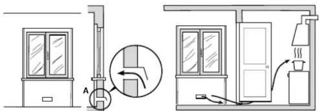
Examples of ventilation holes Enlarging the ventilation slot for comburant air between window and floor
fig. 8A fig. 8B
The air inflow may also be obtained from an adjoining room, provided the latter is not a bedroom or a room where there is a risk of fire, such as warehouses, garages, fuel stores, etc. and is ventilated in compliance with the current standards and regulations. Air from the adjoining room to the one to be ventilated may be made to pass freely through permanent apertures with a cross section at least equal to that indicated above. These apertures may also be obtained by increasing the gap between the door and the floor (fig.8B). If an electric fan is used for extracting the combustion products, the ventilation aperture must be increased in relation to its maximum performance. The electric fan should have a sufficient capacity to guarantee an hourly exchange of air equal to 3 ÷ 5 times the volume of the kitchen. Prolonged, intensive use of the appliance may require extra ventilation, e.g. an open window or a more efficient ventilation system by increasing the extraction power of the electric fan if installed. Liquid petroleum gas descends towards the floor as it is heavier than air. Apertures in the outside walls in rooms containing LPG cylinders should therefore be at floor level, in order to allow any gas from leaks to be expelled. Do not store LPG cylinders (even when empty) in basements or rooms below ground level; it is advisable to keep only the cylinder in use in the room at any one time and connected far from heat sources which could raise its temperature to above 50° C.
Gas supply connection
- Check that the appliance is set for the type of gas available and then connect it to the mains gas piping or the gas cylinder in compliance with current regulations and standards.
- This appliance is designed and set to work with the gas indicated on the label situated on the actual hob. If the gas supply is other than the type for which the appliance has been set, proceed with replacing the corresponding nozzles (provided), following instructions given in the paragraph “Adaptation to different types of gas”.
- For trouble-free operation, suitable use of energy and longer life of the appliance, make sure that the supply pressure complies with the values indicated in the table 1 "burners and nozzles specifications, otherwise install a special pressure regulator on the supply pipe in compliance with current standards and regulations.
- Connect in such a way that the appliance is subjected to no strain whatsoever.
Either a rigid metal pipe with fittings in compliance with the standards in force must be used for connecting to the nipple union (threaded 1/2 "G male fitting) situated at the rear of the appliance to the right (fig.9), or flexible steel pipe in compliance with the standards in force, which must not exceed 2000 mm in length.
Should it be necessary to turn the fitting, the gasket (supplied with the appliance) must be replaced.
fig.9
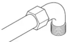
Upon completion of installation, check the gas circuit, the internal connections and the taps for leaks using a soapy solution (never a flame).
Also check that the connecting pipe cannot come into contact with moving parts which could damage or crush it. Make sure that the natural gas pipe is adequate for a sufficient supply to the appliance when all the burners are lit.
Important: A pressure regulator, in compliance with the standards in force, must be inserted when connecting to a liquid gas supply (in a cylinder).
Adaptation to a different type of gas
If the hob is to be converted for use with a type of gas other than that for which it was set in the factory (indicated on the label to be found on the hob), the burner nozzles should be replaced as follows:
- Remove the pan supports and the burners.
- Unscrew the nozzles "A" (fig.10) using a 7 mm socket wrench and replace them with the ones which have a diameter suitable for the type of gas to be used, according to the table 1 "burners and nozzles specifications).
- Reassemble the parts following the instructions in reverse order.
- On completing the operation, replace the old rating label with the one showing the new type of gas; the sticker is available from our Service Centres.
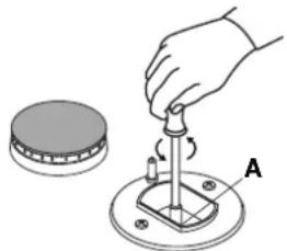
fig.10 fig.11

Replacing the nozzles on separate "double flame" burners:
- remove the grids and slide the burners from their housings. The burner consists of 2 separate parts (Fig. C and fig. D);
- unscrew the burers with a 7 mm wrench spanner. The internal burner has a nozzle, the external burner has two (of the same size). Replace the nozzle with models suited to the new type of gas (see table 1).
- replace all the components by repeating the steps in reverse order.

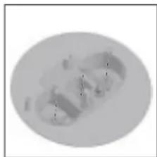
Fig. C Fig. D
Regulation of Air Supply to the Burner
The burners do not need a primary air regulator.
Minimum Regulation
- Turn the gas valve to minimum. - Remove the tap knob and turn the adjusting screw, situated inside of the tap stem (fig.11), using a screwdriver (loosening the screw increases the height of the flame, tightening decreases it).
N.B.: In the case of liquid gas, the regulation screw must be fully screwed in (clockwise).
- Make sure that, when the knob is turned rapidly high to low, the flame does not go out.
- In the event of a malfunction on appliances with the security device (thermocouple) when the gas supply is set at minimum, increase the minimum supply levels using the regulator screw.
Once the adjustment has been made, apply sealing wax, or a suitable substitute, to the old seals on the by-pass. THE APPLIANCE MUST BE EARTHED
The hob is designed to work with alternating current at the supply voltage and frequency indicated on the rating plate
ELECTRICAL CONNECTION
(situated under the hob or at the end of the instruction booklet). Make sure that the local supply voltage corresponds to the voltage indicated on the rating plate.
Connecting the supply cable to the mains electricity supply
For models supplied without a plug, fit a standard plug, suitable for the load indicated on the rating plate, onto the cable and connect to a suitable socket. To connect directly to the mains supply, a double-pole switch with a contact separation of at least 3 mm suitable for the load and complying with current standards and regulations, must be fitted between the appliance and the mains supply outlet. The yellow-green earth wire must not be interrupted by the switch. The supply cable must be in such a position that no part of it can reach a temperature of 50 °C above room temperature. For installation above a built-under oven, the hob and the oven must be connected separately to the electricity supply both for safety reasons and for easy removal of the oven if necessary. Do not use adapters or shunts as they could cause heating or burning. Before connecting to the power supply, make sure that:
- the limiter valve and the domestic system can withstand the load from the appliance (see rating plate);
- the supply system is efficiently earthed according to standards and laws in force;
- the socket or double-pole switch are easily accessible when the appliance is installed.
Important: the wires in the mains lead are coloured in accordance with the following code:
Green & Yellow - Earth
Blue - Neutral
Brown - Live
As the colours of the wires in the mains lead may not correspond with the coloured markings identifying the terminals in your plug, proceed as follows:
Connect the Green & Yellow wire to terminal marked "E" or
or coloured Green or Green & Yellow.
Connect the Brown wire to the terminal marked "L" or coloured Red. Connect the Blue wire to the terminal marked "N" or coloured Black. FAILURE TO OBSERVE THE ACCIDENT-PREVENTION REGULATIONS RELIEVES THE MANUFACTURER OF ALL LIABILITY.
Replacing the cable
Use a rubber cable of the type H05VV-F with a suitable cross section 3 x 1.5 mm². The yellow-green earth wire must be 2-3 cm longer than the other wires.
BURNERS AND NOZZLES SPECIFICATIONS
| Table 1 | Liquid gas | Natural gas | |||||||
| BURNER | Diameter (mm) | Thermal power kW (H.s.*) | By-pass 1/100 (mm) | Injector 1/100 (mm) | Flow * g/h | Injector 1/100 (mm) | Flow* l/h G20 | ||
| Nomin. | Reduc. | G30 | G31 | ||||||
| C.Rapid | 100 | 3.00 | 0.7 | 40 | 86 | 218 | 214 | 116 | 286 |
| B. Semi-rapid | 75 | 1.65 | 0.4 | 30 | 64 | 120 | 118 | 96 | 157 |
| A. Auxiliary | 55 | 1.00 | 0.3 | 27 | 50 | 73 | 71 | 71 | 95 |
| I. Double flame DC DR (internal) | 30 | 0.90 | 0.4 | 30 | 44 | 65 | 64 | 74 | 86 |
| I. Double Flame DC DR (external) | 130 | 4.10 | 1.3 | 57 | 70 | 298 | 293 | 110 | 390 |
| Supply pressure | Nominal Minimum Maximum | 28-30 20 35 | 37 25 45 | 20 17 25 | |||||
* At 15°C and 1013 mbar-dry gas
Propane G31 H.s. = 50,37 MJ/kg
Butane G30 H.s. = 49,47 MJ/kg
Methane G20 H.s. = 37,78 MJ/m 3
TECHNICAL SPECIFICATIONS
ENERGY LABEL
Directive 2002/40/EC on the label of electric ovens
Norm EN 50304
Energy consumption for Natural convection
heating mode: Convection
Declared energy consumption for Forced convection Class
heating mode: □an assisted
MAXIFOUR - COMMENT L'UTILISER
FOUR ÉLECTRIQUE MULTIFONCTIONS
fig 4
PROGRAMMATEUR ÉLECTRONIQUE
fig.7


fig.11
fig.10
Réglage des minima
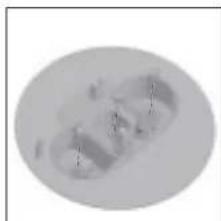
Fig. C Fig. D
BRANCHEMENT ÉLECTRIQUE
L'APPAREIL DOIT NECESSAIREMENT ÊTRE RELIÉ A LA TERRE.
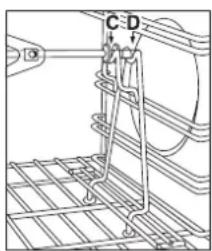
Abb. 2a Abb. 2b
SO HALTE ICH DAS GERÄT IN TOPFORM

Abb. 3
Abb. 4
Abb.10 Abb.11

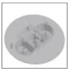
Abb. C Abb. D
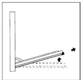
Fig 3
Fig 4
fig.5
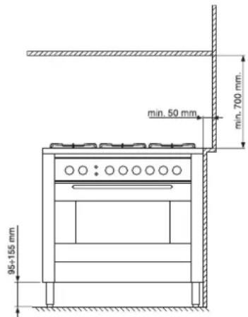
fig.10
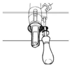
fig.11
Afb. C Afb. D

fig. 4
fig.7


fig.10 fig.11
Fig. C Fig. D
Desmontar/montar a porta do forno
fig 4
fig.7
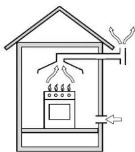
Na chaminé ou condutor de fumo ramificado Directamente para fora (reservada aos aparelhos de cozedura)
fig.9
fig.10
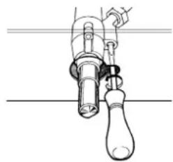
fig.11
Regulação mínimos
Fig. C Fig. D

- FORNO MULTIFUNZIONE
- THESE INSTRUCTIONS ARE ONLY VALID FOR THE COUNTRIES OF DESTINATION WHOSE SYMBOLS ARE SHOWN IN THE BOOKLET AND THE APPLIANCE RATING PLATE
- DISPOSAL OF OLD ELECTRICAL APPLIANCES
- THIS APPLIANCE CONFORMS WITH THE FOLLOWING EUROPEAN ECONOMIC COMMUNITY DIRECTIVES
- COOKER DESCRIPTION
- INSTRUCTIONS FOR USE
- HOB OPERATION
- IMPORTANT
- USING THE BURNERS
- THE "SEPARATE DOUBLE FLAME" BURNER
- TO ENSURE THAT THE DOUBLE-FLAME BURNER IS USED TO ITS FULL POTENTIAL, NEVER SET THE INSIDE RING TO MINIMUM AND THE OUTSIDE RING TO MAXIMUM AT THE SAME TIME
- THE "MAXIOVEN
- MULTI-FUNCTION OVEN
- OVEN LIGHT
- INDICATOR LIGHT "S
- SPIT - ROTISSERIE
- HOW TO KEEP YOUR OVEN IN SHAPE
- BEFORE CLEANING YOUR OVEN, OR PERFORMING MAINTENANCE, DISCONNECT IT FROM THE POWER SUPPLY
- REPLACING THE LAMP IN THE OVEN
- DISASSEMBLING/ASSEMBLING THE OVEN DOOR
- TO REASSEMBLE THE DOOR
- THE ELECTRONIC PROGRAMMER
- ADJUSTING THE CLOCK
- MANUAL OVEN MODE (PROGRAMMING EXCLUDED)
- SEMI-AUTOMATIC OVEN MODE
- MINUTE MINDER
- BUZZER
- PROGRAM CONTROL
- ERASING PROGRAMS
- PRACTICAL COOKING ADVICE
- PREHEATING
- USING THE GRILL
- BAKING PASTRIES
- COOKING PIZZA
- MODE
- COOKING FISH AND MEAT
- COOKING TIPS
- NOTES
- INSTALLATION
- CATEGORY: II 2H3+ CLASS: 1
- POSITIONING
- KITCHEN VENTILATION
- GAS SUPPLY CONNECTION
- ADAPTATION TO A DIFFERENT TYPE OF GAS
- REPLACING THE NOZZLES ON SEPARATE "DOUBLE FLAME" BURNERS
- REGULATION OF AIR SUPPLY TO THE BURNER
- MINIMUM REGULATION
- ELECTRICAL CONNECTION
- CONNECTING THE SUPPLY CABLE TO THE MAINS ELECTRICITY SUPPLY
- REPLACING THE CABLE
- TECHNICAL SPECIFICATIONS
- ENERGY LABEL
- MAXIFOUR - COMMENT L'UTILISER
- FOUR ÉLECTRIQUE MULTIFONCTIONS
- PROGRAMMATEUR ÉLECTRONIQUE
- RÉGLAGE DES MINIMA
- BRANCHEMENT ÉLECTRIQUE
- SO HALTE ICH DAS GERÄT IN TOPFORM
- DESMONTAR/MONTAR A PORTA DO FORNO
- REGULAÇÃO MÍNIMOS
Brand : Hotpoint Ariston
Model : XC902GHDC.3
Category : Cooker