
DVM205AM - Multimeter VELLEMAN - Free user manual and instructions
Find the device manual for free DVM205AM VELLEMAN in PDF.


| Product Type | Digital Multimeter |
| Brand | Velleman |
| Model | DVM205AM |
| Display | 2000 counts LCD |
| DC Voltage Range | 200mV to 600V |
| AC Voltage Range | 200V to 600V |
| DC Current Range | 200µA to 10A |
| Resistance Range | 200Ω to 20MΩ |
| Additional Functions | Diode test, Continuity buzzer, Transistor hFE test |
| Safety Rating | CAT II 600V |
| Power Supply | 9V battery (6F22 or NEDA 1604) |
| Dimensions | 180 x 80 x 30 mm |
| Weight | 350 g |
| Accessories Included | Test leads, battery, manual |
| Cleaning | Wipe with dry cloth, no solvents |
| Storage Temperature | -10°C to 50°C |
Frequently Asked Questions - DVM205AM VELLEMAN
User questions about DVM205AM VELLEMAN
0 question about this device. Answer the ones you know or ask your own.
Ask a new question about this device
Download the instructions for your Multimeter in PDF format for free! Find your manual DVM205AM - VELLEMAN and take your electronic device back in hand. On this page are published all the documents necessary for the use of your device. DVM205AM by VELLEMAN.
USER MANUAL DVM205AM VELLEMAN
natural_image
Digital multimeter displaying 003.1 with red and black test probes and a digital display (no readable text or symbols on main components)USER MANUAL 3
GEBRUIKERSHANDLEIDING 8
NOTICE D'EMPLOI 13
MANUAL DEL USUARIO 18
To all residents of the European Union
Important environmental information about this product

This symbol on the device or the package indicates that disposal of the device after its lifecycle could harm the environment.
Do not dispose of the unit (or batteries) as unsorted municipal waste; it should be taken to a specialized company for recycling.
This device should be returned to your distributor or to a local recycling service. Respect the local environmental rules.
If in doubt, contact your local waste disposal authorities.
Thank you for buying the DVM205AM! Please read the manual thoroughly before bringing this device into service. If the device was damaged in transit, you should contact your dealer and postpone installation of this device.
- Familiarise yourself with the functions of the device before actually using it.
- All modifications of the device are forbidden for safety reasons. Damage caused by user modifications to the device is not covered by the warranty.
- Only use the device for its intended purpose. Using the device in an unauthorised way will void the warranty.
- Damage caused by disregard of certain guidelines in this manual is not covered by the warranty and the dealer will not accept responsibility for any ensuing defects or problems.
- Refert: the Velleman® Service and Quality Warranty on the last pages of this manual.
2. Safety Precautions
- Do not use your DVM2.05AM if the device itself or the test leads look damaged, or if you suspect that it is not operating properly.
- Never ground yourself when making electrical measurements. Do not touch exposed metal pipes, outlets, fixtures, etc. which might be at ground potential. Keep your body isolated from ground by wearing dry clothing and shoes with rubber soles and using rubber mats or other approved insulating material.
- Turn d'f the power to the circuit under r test before cutting, unsoldering or breaking it. Small amounts of current: can be dangerous.
- Be cautious when working above 60VDC or 30VAC as such voltages pose a shock hazard.
- When using the probes, make sure to keep your fingers behind the finger guards on the probes.
- Measuring voltage that exceeds the limits of the multimeter may damage your DVM205AM and expose the operator to a shock hazard. Always respect the meter voltage and current limits as stated on the front of the meter.
- Neverapply voltage or current to the meter that exceeds the specified maximum:
| Function | Maximum Input |
| VDC or VAC | 1000VDC; 750VAC |
| mA DC/AC | 400mA DC/AC |
| A DC/AC | 10A DC/AC (30 seconds max every 15 minutes) |
| Frequency, resistance, temperature, capacitance, pulse width, dwell period, duty cycle, diode test, continuity, RPM | 250VDC/AC |
SAFETY SYMBOLS
 | This symbol adjacent to another symbol, terminal or operating device indicates that the operator must refer to an explanation in this manual to avoid injury or damage to the meter. |
| This symbol indicates a potentially hazardous situation, which if not avoided, could result in death or serious injury. | |
| [CAUTION] | This symbol indicates a potentially hazardous situation which, if not avoided, may result in damage to the device. |
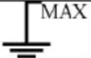 | This symbol advises the user that the terminal(s) so marked must not be connected to a circuit point at which the voltage with respect to ground exceeds (in this case) 500V AC/DC. |
| [TOHZ] | This symbol adjacent to one or more terminals identifies :hem as being associated with ranges that may, in normal use, be subjected to particularly hazardous voltages. For maximum safety, the meter and its test leads should not be handled when these terminals are energized. |
3. Front Panel Description
Refer to page 2 of this manual.
SYMBOLS
| Continuity | |
| BAT | Low Battery |
| Diode | |
| DATA HOLD | Data Hold |
| AUTO | Auto ranging |
| AC | Alternating Current or Voltage |
| DC | Direct Current or Voltage |
4. Specifications
Compliant with
Insulation
Overvoltage category
Display
Polarity
Overrange indication
Low-battery indication
Measurement rate
Auto power off
Operating temperature
Storage temperature
Max. altitude (indoors)
Pollution degrée
Power source
Dimensions
Weight
Fuse
IEC1010-1 EN61010-1
Class2, double insulation
CATIII 006, CATII 1000V
large 4-digit LCD with symbol signs
automatic, negative polarity indication
"OL"
"BAT" is displayed when the battery voltage drops below operating level
device powers off after approx. 15 minutes of inactivity
°C to 5 0°C (32°F to 122°F) @ <70%RH
-20°C 600C (-4°F to 140°F) @ <80%RH
2000m
2
one 9V-battery (e.g. 6F22)
146 x 66.2 x 41.5 (H x W x D)
approx. 100g
400mA range: 250V / 500mA fast blow / 10A range: 250V/10A fast blow
All accuracy indications below are valid for 18-28°C (65-83°F) @ <70% RH.
| Range | Resolution | Accuracy | other | |
| RPM 2-8CYL 50 | 0~1 0000 RPM | 10 RPM | ±2.5% rdg ±4 digits | Overload protection: 250Vac/dc rms |
| DWELL 2 CYL 0~180 .0° | 0.1° | ±2.5% rdg ±4 digits | Overload protection: 250Vac/dc rms | |
| DWELL 4 CYL 0~90. 0° | ||||
| DWELL 5 CYL 0~72. 0° | ||||
| DWELL 6 CYL 0~60. 0° | ||||
| DWELL 8 CYL 0~45. 0° | ||||
| DC voltage (auto-ranging) | 400.0 mV | 0.1mV | ±0.5% rd g ±2 digits | Input impedance: 10MΩMax. input: 1000Vdc rms |
| 4.000V | 1mV | ±1.5% rd g ±2 digits | ||
| 40.00V | 10mV | |||
| 400.0V | 100mV | |||
| 1000V | 1V | ±1.8% rd g ±2 digits | ||
| AC voltage (auto-ranging except 400mV) | 400.0 mV | 0.1mV | ±1.5% rd g ±30 digits | Input impedance: 10MΩFrequency range: 50 to 400HzMax input: 750Vac rms |
| 4.000V | 1mV | ±1.0% rd g ±3 digits | ||
| 40.00V | 10mV | ±1.5% rd g ±3 digits | ||
| 400.0V | 100mV | |||
| 750V | 1V | ±2.0% rd g ±4 digits | ||
| DC current (auto-ranging for μA and mA) | 400.0 μA | 0.1μA | ±1.0% rd g ±3 digits | Overload protection: 0.5A/250V and 10A/250V fuseMax. input: 400mAADC rms on μA/mA ranges10Adc rms on 10A range |
| 4000μA | 1μA | ±1.5% rd g ±3 digits | ||
| 40.00 mA | 10μA | |||
| 400.0 mA | 100μA | |||
| 4A | 1mA | ±2.5% rd g ±5 digits | ||
| 10A | 10mA | |||
| AC current (auto-ranging for μA and mA) | 400.0 μA | 0.1μA | ±1.5% rd g ±5 digits | Overload protection: 0.5A/250V and 10A/250V fuseFrequency range: 50 to 400HzMax. input: 400mAAC rms on μA/mA ranges10Aac rms on 10A range |
| 4000μA | 1μA | ±1.8% rd g ±5 digits | ||
| 40.00 mA | 10μA | |||
| 400.0 mA | 100μA | |||
| 4A | 1mA | ±3.0% rd g ±7 digits | ||
| 10A | 10mA | |||
| Resistance (auto-ranging) | 400.0 Ω | 0.1Ω | ±1.2% rd g ±4 digits | Input protection: 250Vdc/ac rms |
| 4000 Ω | 1 | Ω±1.0% rd g ±2 digits | ||
| 40.00 kΩ | 10Ω | ±1.2% rd g ±2 digits | ||
| DVM205AM | ||||
| Range | Resolution | Accuracy | other | |
| 400.0kΩ | 100 Ω | |||
| 4.000MΩ | 1kΩ | |||
| 40.00MΩ | 10kΩ | ±2.0% rdg ±3 digits | ||
| Capacitance (auto-ranging) | 40.00nF | 10pF | ±5.0% g ±7 rddigits | Input protection: 250Vdc/ac rms |
| 400.0nF | 0.1nF | ±3.0% rdg ±5 digits | ||
| 4.000μF | 1nF | |||
| 40.00μF | 10nF | |||
| 100.0μF | 0.1μF | ±5.0%g ±5 digitsrd | ||
| Frequency (auto-ranging) | 9.999Hz 0.001Hz | ±1.5% rdg ±5 digits | Sensitivity:<0.5Vrms while ≤1MHz>3Vrms while >1MHzOverload protection: 250Vdc/ac rms | |
| 99.99Hz 0.01Hz | ||||
| 999.9Hz 0.1Hz | ±1.2% rdg ±3 digits | |||
| 9.999kHz 1Hz | ||||
| 99.99kHz 10Hz | ||||
| 999.9kHz 100Hz | ||||
| 9.999MHz 1kHz | ±1.5% | rd ±4 digits | ||
| Duty cycle 0.1%~99.9% 0.1% | ±1.2% rdg | ±2 digits | Pulse width: >100μs, 100msFrequency width: 5Hz-150kHzSensitivity: <0.5VrmsOverload protection: 250Vac/dc rms | |
| Period | 2.0ms~20.0ms | 0.1ms ±3% | rdg ±10 digits | Overload protection: 250Vac/dc rms |
| Pulse width | 2.0ms~10.0ms | 0.1ms ±3% | rdg ±10 digits | Overload protection: 250Vac/dc rms |
| Temperature | -20~+760°C | 1°C | ±3% rdg ±3 digits(meter only; probe accuracy not included) | Sensor: K-type thermocouple |
| -4~+1400°F | 1°F | |||
| Diode test | 0.3mA typical | 1mV | ±10% rdg ±5 digits | Open circuit voltage: 1.5Vdc typicalOverload protection: 250Vac/dc rms |
| Audible Continuity | Audible threshold: less than 50ΩTest current: <0.3mAOverload protection on all ranges: 250Vdc/ac rms | |||
5. Control Buttons
a) Hz / % Button (fig. p.2 #2)
This button allows you to choose between frequency and the duty cycle in a frequency range.
Press the HZ/% button to measure the frequency or the duty cycle while measuring voltage or current.
For the voltage/current requirements and frequency range, see the following table (for reference only):
| Range (AC/DC) | Sensitivity | Frequency width |
| 4V | ≥1.5V rms | 5Hz~10kHz |
| 40V, 400V | ≥6.5V rms | 5Hz~20kHz |
| ≥12V rms | 5Hz~200kHz | |
| 1000V/750V | ≥420V rms | 50Hz~1kHz |
| 400mA | ≥45mA rms | 5Hz~5kHz |
| 10A | ≥4A rms | 5Hz~1kHz |
Press the HZ/% button again to return to regular voltage or current measurement.
b) Range Button (fig. p.2 #3)
When the meter is switched on, it automatically goes into auto ranging ("AUTO" indication on the display). This automatically selects the best range for the measurements being made and is generally the best mode for most measurements. For measurements situations requiring a manually selected range, perform the following steps:
- Press the RANGE button; the "AUTO" indication on the display will disappear.
- Press the RANGE button repeatedly to skip through the available ranges until the required one is selected.
- To return to auto ranging, press and hold the RANGE button for more than 2 seconds.
c) Relative Button (fig. p.2 #4)
The relative measurement feature allows you to make measurements relative to a stored reference value. A reference voltage, current etc. can be stored and measurements made in comparison to that value. The displayed value is the difference between the reference value and the measured value.
- Perform any measurement as described in the operating instructions.
DVM205AM
- Press the REL(ative) button to store the reading in the display and the REL indication will appear on the display.
- The display will now indicate the difference between the stored value and the measured value.
- Press the REL button to switch the relative function off and return to normal operation.
d) Data Hold / Backlight Button (fig. p.2 #5)
The data hold function allows the meter to "freeze" a measurement for later reference.
- Press the DATA HOLD button to freeze the reading on the display. The HOLD indication will be displayed.
- Press the DATA HOLD button again to return to normal operation.
Press the button for more than 2 seconds to switch the display backlight on or off.
e) Mode Button (fig. p.2 #6)
Use the Mode button to select AC/DC voltage, AC/DC current, resistance, diode, continuity or capacitance check.
f) °C/°F Button (fig. p.2 #7)
The °C/°F button is used to switch between °C and °F when measuring temperature.
The default temperature unit is ^ C.
6. Operating Instructions
- Set the selection switch to the OFF position when the device is not being used. In order to prevent battery leakage, the device automatically powers down when it has not been used for approx. 15 minutes.
- If "OL" appears in the display during a measurement, the value exceeds the selected range. Select a higher range.
- When a low voltage range is selected, the display may show a varying reading although the leads are not connected to a device or circuit. This is normal and is caused by the high input sensitivity. The reading will stabilize and give a proper measurement when connected to a circuit.
a) Voltage Measurements
- Plug the black test lead in COM (fig. p.2 #10) and the red test lead in the + connector (#11).
- Set the selection switch (#8) to the Vdc/ac position and press MODE (#6) to select AC or DC voltage.
- Put the leads over the load to be measured and read the measured value from the LCD.
NOTE: Pressing the Hz/% button will cause the display to switch to frequency or duty cycle.
b) Current Measurements
CAUTION: Do not make current measurements on the 10A scale for longer than 30 seconds every 15 minutes. Exceeding 30 seconds may cause damage to the meter and/or the test leads.
- Plug the black test lead in the COM jack (#10) and the red test lead in the + jack (11) for max. 400mA measurements, or in the 10A jack (#9) for max. 10A measurements.
- Set the selection switch (#2) to the desired current measuring position (μA, mA or A).
- Press MODE (#6) to select AC or DC current.
- Put the leads in series with the load under test and read the measured value from the LCD.
NOTE: Pressing the Hz/% button will cause the display to switch to frequency or duty cycle.
c) Resistance / Diode / Continuity / Capacitance Measurements
CAUTION: To avoid electric shock, make sure all power of the circuit to be measured is off and all capacitors are fully discharged when measuring resistance or capacitance.
- Plug the black test lead in COM and the red test lead in the + connector (#11).
- Set the selection switch (#8) to the Ω→|· CAP position.
- Press the MODE button to select Ω, CAP.
- Connect the test leads to the component or circuit to be measured and read the measured value from the LCD.
- When testing continuity, a beeping sound shall be heard if the resistance is <30Ω.
- When measuring the forward voltage across a diode, a normal diode will indicate 0.4V or 0.7V. The reverse voltage will indicate "OL" (same as in open condition). A short-circuited diode will have a 0mV reading.
d) Frequency or Duty Cycle Measurements
- Plug the black test lead in COM and the red test lead in the + connector (#11).
- Set the selection switch (#8) to the Hz/%duty position.
- Press the Hz/% button to select "Hz" or "%".
- Connect the test leads to the circuit under test and read the frequency or the duty cycle on the display.
e) Temperature Measurements
- Insert the type K thermocouple in the appropriate sockets: negative plug in COM, positive plug in +.
- Set the selection switch (#2) to °C/°F.
- Press the °C/°F button to select °C or °F.
DVM205AM
- Touch the target surface with the extremity of the probe and read the measured temperature from the LCD.
f) Period Measurements
- Plug the black test lead in COM and the red test lead in the + connector (#11).
- Set the selection switch (#2) to "Period ms".
- Connect the black test lead to ground and the red test lead to the wire that connects to the component to be measured.
- Read the measured value on the display.
NOTE: The applied time for most fuel injectors is displayed on the negative (-) slope.
g) Pulse Width Measurements
- Plug the black test lead in COM and the red test lead in the + connector (#11).
- Set the selection switch (#2) to "Pulse Width ms".
- Connect the black test lead to ground and the red test lead to the wire that connects to the component to be measured.
- Read the measured value on the display.
h) RPM Measure ments
- Plug the black test lead in COM and the red test lead in the + connector (#11).
- Set the selection switch (#2) to the applicable position (2, 4, 5, 6 or 8CYL on the RPMx10 range).
- Connect the black test lead to the negative pole of the car battery and connect the red test lead to a breaker point.
- Crank the engine; the RPM (rotations per minute) will be displayed.
i) Dwell Angle Measurements
- Plug the black test lead in COM and the red test lead in the + connector (#11).
- Set the selection switch (#2) to the applicable position (2, 4, 5, 6 or 8CYL on the DWELL range).
- Connect the black test lead to the negative pole of the car battery and connect the red test lead to a breaker point.
- Crank the engine; the dwell angle will be displayed.
NOTE: The dwell angle needs only be tested in cars with a traditional ignition system. Cars with an electronic ignition system don't need to have the dwell angle tested.

7. Ma intenance
CAUTION: Before opening the case, set the selection switch to OFF and disconnect all test leads in order to avoid electric shock hazard. Do not switch the device on before the battery/fuse compartment door is closed securely.
If your DVM205AM should not be operating properly, check the battery and fuses to make sure they are not faulty and are properly inserted.
a) Install or Replace a Battery
The battery should be replaced when "BAT" appears on the display. Turn loose the screws at the back and open the case. Remove the old battery (when replacing) and install a new one (1 x 9V-battery type 6F22 or equivalent) - mind the polarity! Close the case and tighten the screws.
b) Replace a Fuse
The fuse rarely needs to be replaced; a blown fuse is usually the result of the operator's error. Turn loose the screws at the back and open the case. Replace the old fuse (250V/0.5A fast blow for 400mA range; 250V/10A fast blow for 10A range), close the case and tighten the screws.
Use this device with original accessories only. Velleman nv cannot be held responsible in the event of damage or injury resulted from (incorrect) use of this device.
For more info concerning this product, please visit our website: www.velleman.eu.
The information in this manual is subject to change without prior notice.
© COPYRIGHT NOTICE
This manual is copyrighted. The copyright to this manual is owned by Vellennan nv. All worldwide rights reserved. No part of this manual may be copied, reproduced, translated or reduced to any electronic medium or otherwise with out the prior written consent of the copyright holder.
7. Mantenimiento
Velleman® Service and Quality Warranty
Velleman® has over 35 years of experience in the electronics world and distributes its products in more than 85 countries. All our products fulfil strict quality requirements and legal stipulations in the EU. In order to ensure the quality, our products regularly go through an extra quality check, both by an internal quality department and by specialized external organisations. If, all precautionary measures notwithstanding, problems should occur, please make appeal to our warranty (see guarantee conditions).
General Warranty Conditions Concerning Consumer Products (for EU):
- All consumer products are subject to a 24-month warranty on production flaws and defective material as from the original date of purchase.
- Velleman® can decide to replace an article with an equivalent article, or to refund the retail value totally or partially when the complaint is valid and a free repair or replacement of the article is impossible, or if the expenses are out of proportion.
You will be delivered a replacing article or a refund at the value of 100% of the purchase price in case of a flaw occurred in the first year after the date of purchase and delivery, or a replacing article at 50% of the purchase price or a refund at the value of 50% of the retail value in case of a flaw occurred in the second year after the date of purchase and delivery.
- Not covered by warranty:
- all direct or indirect damage caused after delivery to the article (e.g. by oxidation, shocks, falls, dust, dirt, humidity...), and by the article, as well as its contents (e.g. data loss), compensation for loss of profits;
- frequently replaced consumable goods, parts or accessories such as batteries, lamps, rubber parts, drive belts... (unlimited list);
- flaws resulting from fire, water damage, lightning, accident, natural disaster, etc. ...;
- flaws caused deliberately, negligently or resulting from improper handling, negligent maintenance, abusive use or use contrary to the manufacturer's instructions;
- damage caused by a commercial, professional or collective use of the article (the warranty validity will be reduced to six (6) months when the article is used professionally);
- damage resulting from an inappropriate packing and shipping of the article;
- all damage caused by modification, repair or alteration performed by a third party without written permission by Velleman®.
- Articles to be repaired must be delivered to your Velleman® dealer, solidly packed (preferably in the original packaging), and be completed with the original receipt of purchase and a clear flaw description.
- Hint: In order to save on cost and time, please reread the manual and check if the flaw is caused by obvious causes prior to presenting the article for repair. Note that returning a non-defective article can also involve handling costs.
- Repairs occurring after warranty expiration are subject to shipping costs.
- The above conditions are without prejudice to all commercial warranties.
The above enumeration is subject to modification according to the article (see article's manual).
NL


- To all residents of the European Union
- Important environmental information about this product
- If in doubt, contact your local waste disposal authorities.
- Safety Precautions
- Front Panel Description
- SYMBOLS
- Specifications
- Control Buttons
- DVM205AM
- Operating Instructions
- f) Period Measurements
- g) Pulse Width Measurements
- h) RPM Measure ments
- i) Dwell Angle Measurements
- Ma intenance
- a) Install or Replace a Battery
- b) Replace a Fuse
- Use this device with original accessories only. Velleman nv cannot be held responsible in the event of damage or injury resulted from (incorrect) use of this device.
- © COPYRIGHT NOTICE
- Mantenimiento
- Velleman® Service and Quality Warranty
- General Warranty Conditions Concerning Consumer Products (for EU):
- The above enumeration is subject to modification according to the article (see article's manual).
- NL
Brand : VELLEMAN
Model : DVM205AM
Category : Multimeter