
DVM2000 - Multimeter VELLEMAN - Free user manual and instructions
Find the device manual for free DVM2000 VELLEMAN in PDF.


| Product type | Digital multimeter |
| Model | DVM2000 |
| Brand | Velleman |
| Display | LCD 6000 counts |
| DC accuracy | ±0.5% |
| Functions | AC/DC voltage, AC/DC current, resistance, continuity, diode test, capacitance, frequency, temperature |
| DC voltage range | 600 mV to 600 V |
| AC voltage range | 600 mV to 600 V |
| DC current range | 600 µA to 10 A |
| AC current range | 600 µA to 10 A |
| Resistance range | 600 Ω to 60 MΩ |
| Capacitance | 10 nF to 100 mF |
| Frequency | 10 Hz to 10 MHz |
| Temperature | -20°C to 1000°C (with type K thermocouple) |
| Safety | CAT II 600 V, CAT I 1000 V |
| Power supply | 9 V battery (6F22) |
| Dimensions | 180 x 87 x 47 mm |
| Weight | 340 g |
| Included accessories | Test leads, type K thermocouple, battery |
| Maintenance and cleaning | Clean with a dry cloth, avoid moisture |
| Warranty | 2 years |
Frequently Asked Questions - DVM2000 VELLEMAN
User questions about DVM2000 VELLEMAN
0 question about this device. Answer the ones you know or ask your own.
Ask a new question about this device
Download the instructions for your Multimeter in PDF format for free! Find your manual DVM2000 - VELLEMAN and take your electronic device back in hand. On this page are published all the documents necessary for the use of your device. DVM2000 by VELLEMAN.
USER MANUAL DVM2000 VELLEMAN
natural_image
Collection of electrical probes and cables with no visible text or symbols
CE
DVM2000 – HIGH-ACCURACY TRUE RMS MULTIMETER - 50000 COUNTS
1. Introduction
To all residents of the European Union
Important environmental information about this product

This symbol on the device or the package indicates that disposal of the device after its lifecycle could harm the environment. Do not dispose of the unit (or batteries) as unsorted municipal waste; it should be taken to a specialized company for recycling. This device should be returned to your distributor or to a local recycling service.
Respect the local environmental rules.
If in doubt, contact your local waste disposal authorities.
Thank you for choosing Velleman! Please read the manual thoroughly before bringing this device into service. If the device was damaged in transit, don't install or use it and contact your dealer.
2. Safety Instructions
This multimeter has been designed according to IEC-1010-1 concerning electronic measuring instruments with an overvoltage category CAT III 1000V and pollution 2. This multimeter complies with 89/336/EEC, 73/23/EEC and 93/68/EEC.
- Damage caused by disregard of certain guidelines in this manual is not covered by the warranty and the dealer will not accept responsibility for any ensuing defects or problems.
- Check the meter before every use. Never use a damaged or deformed multimeter.
- Do not use the multimeter in an environment with combustible gases, steam or dust.
- Always be careful when handling voltages > 60VDC or > 50VAC RMS. Always keep fingers behind the guards. Keep your body insulated when measuring.
- Never measure voltages exceeding 1000VAC or 1000VDC to ensure your safety.
- Replace the batteries when the + symbol appears. Disconnect the measuring probes from any circuit before opening the multimeter.
• Repair and calibration must be carried out by experienced professionals only.
3. Description
a. Multimeter
- V/Ω/Hz terminal
- COM terminal
- μA/mA terminal
- A terminal
- rotary selection switch
- power switch
- RANGE: range selection key
- SELECT: measuring mode selection key
- WAKE: meter reactivation key
- MAX/MIN: maximum/minimum value display selection key
- REL: relative measuring key
- HOLD: data-hold key
- LIGHT: backlight key
- \~Hz: linear frequency measurement
- LCD display
b. LCD Display

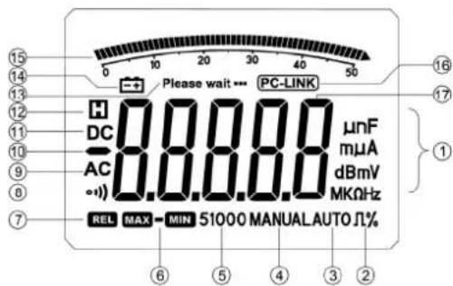
| 1 | μnF | Measurement units. |
| mμA | ||
| dBmV | ||
| MKΩHz | ||
| 2 Π% Duty cycle measurement. | ||
| 3 AUTO Automatic range selection. | ||
| 4 MANUAL Manual range selection. | ||
| 5 | 51000 | Range indication. |
| 6 |  | Maximum/minimum value display. |
| 7 |  | Relative measurement mode. |
| 8 |  | Continuity measurement. |
| 9 AC AC measurement mode. | ||
| 10 | Negative value. | |
| 11 DC DC measurement mode. | ||
| 12 | Data-hold function. | |
| 13 Please wait... Waiting mode. | ||
| 14 | Low battery. | |
| 15 |  | Analogue bar indication. |
| 16 | [PC-LINK] | Multimeter is linked to a PC via USB. |
| 17 | Displayed value. | |
4. Operation
- Backlight
Press LIGHT to switch the backlight on or off. The backlight will automatically go out after 30 seconds. Remember that using the backlight will drain the batteries faster.
- Data Hold
Press HOLD to freeze the displayed value. Press again to resume measurement.
- Automatic Shutoff
The meter shuts off after 15 minutes of inactivity by default. When shut off, press WAKE or turn the rotary selection switch to reactivate the multimeter. To deactivate the automatic shutoff function, press the power switch and WAKE simultaneously. Remember to shut off the multimeter using the power switch after use as the multimeter will still drain batteries when in standby.
• Relative Value Measurement
This function applies for all measurement except for frequency, duty cycle and diode measurements. Press RELΔ to determine the relative value. The next displayed value represents the present measured value minus the recorded relative value. Press again to exit the function.
• Maximum/Minimum Value Measurement
This function applies for all measurement except for frequency and diode measurements. Press MAX/MIN to determine the maximum, the minimum or both values respectively. Hold MAX/MIN pressed for 2 seconds to exit the function.
- Connecting the Multimeter to a Computer
Connect your DVM2000 to a computer using the included optical USB cable. Hold HOLD pressed for 2 seconds to send the data to the computer. You will now be able to edit the recorded data on your computer using the appropriate software. Hold HOLD pressed for 2 seconds to stop sending the data.
• ACV/dBm Measurements

Do not measure voltages exceeding 1000V.
Voltage ranges: 0.5VAC\~1000VAC

○ Switch on your multimeter and set to rotary selector switch to ^ .
- Insert the red and the black measuring probes in the V/Ω/Hz and the COM terminals respectively.

- Select the ACV or dBm measurement mode by pressing SELECT.
○ Connect the measuring probes to the circuit. - Read the measured value. Select a higher range by pressing RANGE when L is displayed.
• DCV/DCV + ACV Measurements

Do not measure voltages exceeding 1000V.
Voltage ranges: 0.5VAC\~1000VAC
- Switch on your multimeter and set to rotary selector switch to
Insert the red and the black measuring probes in the V/Ω/Hz and the COM terminals respectively. - Select the DCV or DCV + ACV measurement mode by pressing SELECT.
- Connect the measuring probes to the circuit.
- Read the measured value. Select a higher range by pressing RANGE when L is displayed.

• DC mV/AC mV/DC mV + AC mV Measurements
Voltage ranges: 1μV\~500mV
○ Switch on your multimeter and set to rotary selector switch to mV.
- Insert the red and the black measuring probes in the V/Ω/Hz and the COM terminals respectively.
○ Select the DC mV, AC mV or DC mV + AC mV measurement mode by pressing SELECT.
○ Connect the measuring probes to the circuit.
- Read the measured value. Select a higher range by pressing RANGE when DL is displayed.
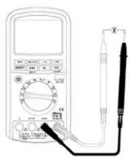

- Logic Frequency/Duty Cycle Measurements
Frequency ranges: 5Kz\~2MHz (Vp 2.5V\~5V), duty cycle ranges: 5\~95%
○ Switch on your multimeter and set to rotary selector switch to Hz%.
- Insert the red and the black measuring probes in the V/Ω/Hz and the COM terminals respectively.
○ Select the Hz or % measurement mode by pressing SELECT.
- Connect the measuring probes to the circuit.
- Read the measured value. A value too low will be displayed as 0.
• Diode Measurements
Diode ranges: 0V\~2.5V
- Switch on your multimeter and set to rotary selector switch to
Insert the red and the black measuring probes in the V/Ω/Hz and the COM terminals respectively.
○ Connect the red measuring probe to the positive pole and the black probe to the negative pole of the diode. The LCD will display the forward voltage drop.
○ Connect the black measuring probe to the positive pole and the red probe to the negative pole of the diode. The backward resistance of the diode is normal when L is displayed.
o Remember to turn off the circuit before measuring diodes integrated in that circuit.

• Resistance/Continuity Measurements
Resistance ranges: 0.01Ω\~50MΩ
- Switch on your multimeter and set to rotary selector switch to
- Insert the red and the black measuring probes in the V/Ω/Hz and the COM terminals respectively.


○ Select the Ω or ⋯ measurement mode by pressing SELECT.
- Connect the measuring probes to the resistor and read the measured resistance value.
- Read the measured value. Select a higher range by pressing RANGE when OL is displayed.
o Simply connect the measuring probes to the circuit for the continuity test.
o Remember to turn off the circuit before measuring resistance or continuity.
- Capacitance Measurements
Capacitance ranges: 10pF\~5000μF
- Switch on your multimeter and set to rotary selector switch to
- Insert the red and the black measuring probes in the V/Ω/Hz and the COM terminals respectively.
- Discharge the capacitor before measurements.
○ Connect the red measuring probe to the positive pole and the black measuring probe to the negative pole of a heteropolar capacitor. - Read the measured value. Select a higher range by pressing RANGE when L is displayed.
• DC μA/AC μA/DC μA + AC μA Measurements
Current ranges: 0.01μA\~5000μA
- Switch on your multimeter and set to rotary selector switch to
- Insert the red and the black measuring probes in the mA/μA and the COM terminals respectively.
○ Select the DC μA, AC μA or DC μA + AC μA measurement mode by pressing SELECT.
Turn off the power to the circuit to be measured. Connect the measuring probes in series to the circuit and turn on the power to the circuit. - Read the measured value. Select a higher range by pressing RANGE when L is displayed.


• DC mA/AC mA/DC mA + AC mA Measurements
Current ranges: 1μA\~500mA
○ Switch on your multimeter and set to rotary selector switch to mA.
- Insert the red and the black measuring probes in the mA/μA and the COM terminals respectively.
○ Select the DC mA, AC mA or DC mA + AC mA measurement mode by pressing SELECT.
Turn off the power to the circuit to be measured. Connect the measuring probes in series to the circuit and turn on the power to the circuit.
- Read the measured value. Select a higher range by pressing RANGE when L is displayed.
• DC A/AC A/DC A + AC A Measurements
Current ranges: 0.1mA\~10A
○ Switch on your multimeter and set to rotary selector switch to .
Insert the red measuring probe in the A terminal and the black measuring probe in the COM terminal.
○ Select the DC A, AC A or DC A + AC A measurement mode by pressing SELECT.
Turn off the power to the circuit to be measured. Connect the measuring probes in series to the circuit and turn on the power to the circuit.
- Read the measured value. Select a higher range by pressing RANGE when L is displayed.
• Linear Frequency Measurements
Frequency ranges: 5Hz\~200kHz
- Press \~Hz to measure the linear frequency when performing voltage or current measurements.
○ Select the range by pressing RANGE.


| Range | Sensitivity |
| 500mV | 100mV |
| 5V | 0.5V |
| 50V | 4V |
| 500V | 40V |
| 1000V | 400V |
| 5000μA | 1mA |
| 500mA | 100mA |
(sine
wave)
- Press \~Hz to exit the function.
5. Cleaning and Maintenance
Battery Replacement
The 4 symbol appears on the LCD as soon as the total voltage of the batteries drops below 6.8V. Before replacement, disconnect the measuring probes from the circuit and turn off the power to the meter. Remove the back cover using an appropriate Philips-head screwdriver. Replace the batteries with batteries of the same specifications respecting the polarity. Close the back cover before use.
Fuse Replacement
Before replacement, disconnect the measuring probes from the circuit and turn off the power to the meter. Remove the back cover using an appropriate Philips-head screwdriver. Replace the fuse with a fuse of the same specifications. Make sure to insert the fuse correctly. Close the back cover before use.
Meter Calibration
Calibration must only be executed by qualified professionals. Please contact your dealer.
Other
Wipe the device regularly with a dry, lint-free cloth. Do not use alcohol or solvents. Keep the multimeter away from rain and moisture. Never use a damaged or deformed multimeter. Please contact your dealer for repairs.
6. Technical Specifications
Accuracy is specified for one year after calibration at operating temperatures of 18^ C \~ 28^ C with a relative humidity at 0% \~ 80%. Accuracy specifications take the form of ± (% of rdg + number of least significant digits).
Environmental Conditions 1000V CAT III
Pollution Degree 2
Altitude < 2000m
Operating Temperature 0°C\~30°C or 32°F\~86°F (< 80% RH, < 10°C)
Storage Temperature -20°C\~60°C or -4°F\~140°F (< 70% RH, batteries removed)
Fuse μA and mA, F630mA / 500V
A, F12.5A / 500V
Display 99999
Over Range Indication yes ("OL")
Low Battery Indication yes ( -+ )
Data Hold yes
Backlight yes
Power Supply 6 x AAA batteries
Dimensions 205 x 97 x 45mm
Weight ± 560g (with batteries)
Accessories 2 x test leads, 1 x optical USB cable, PC-link software, 6 x AAA batteries, manual
AC Voltage/DC + AC Voltage
| Range | Resolution | Accuracy | ||
| 40Hz~1kHz | 1kHz~10kHz | 10kHz~20kHz | ||
| 50mV | 0.001mV | ± (0.5% + 40) | ± (1% + 40) | ± (2.5% + 40) |
| 500mV | 0.0mV | |||
| 5V | 0.1mV | |||
| 50V | 1mV | ± (0.5% + 40) | ± (1% + 40) unspecified | ± (2.5% + 40) |
| 500VV | 10mV | |||
| 1000V | 0.1V | unspecified | unspecified | |
Above accuracies guaranteed within 10%\~100% of the full range.
DC Voltage
| Range | Resolution | Accuracy |
| 50mV 0.001mV ± (0.03% + 10) | ||
| 500mV | 0.01mV | ± (0.03% + 6) |
| 5V | 0.1mV | |
| 50V | 1mV | |
| 500V | 10mV | |
| 1000V | 0.1V | |
Above accuracies guaranteed within the full range.
AC Current/DC + AC Current
| Range | Resolution | Accuracy | Voltage | ||
| 40Hz~1kHz | 1kHz~10kHz | 10kHz~20kHz | |||
| 500μA 0.01μA | ± (0.75% + 20) ± (1% + 20) ± (2% + 20) | 102μV/μA | |||
| 5000μA 0.1μA | ± (0.75% + 10) ± (1% + 10) ± (2% + 10) | ||||
| 50mA 1μA | ± (0.75% + 20) ± (1% + 20) ± (2% + 20) | 1.5mA/mA | |||
| 500mA | 10μA | ± (0.75% + 10) ± (1% + 10) ± (2% + 10) | |||
| 5A | 0.1mA | ± (0.75% + 20) | ± (1.5% + 20) | ± (5% + 20) | 30mV/A |
| 10A | 1mA | ± (1.0% + 10) | ± (1.5% + 10) | unspecified | |
Above accuracies guaranteed within 10%\~100% of the full range.
DC Current
| Range | Resolution | Accuracy | Voltage |
| 500μA 0.01μA ± (0.15% + 15) | 102μV/μA | ||
| 5000μA | 0.1μA | ± (0.15% + 10) | |
| 50mA | 1μA | 1.5mA/mA | |
| 500mA | 10μA | ||
| 5A | 0.1mA | ± (0.5% + 10) 30mV/A | |
| 10A | 1mA | ||
Above accuracies guaranteed within the full range.
Resistance
| Range | Resolution | Accuracy |
| 500Ω | 0.01Ω | ± (0.1% + 10) |
| 5kΩ | 0.1Ω | (0.1% + 5) |
| 50kΩ | 1 | |
| 500kΩ | 10Ω | |
| 5MΩ | 100Ω | ± (0.1% + 10) |
| 50MΩ | 1kΩ | ± (0.5% + 10) |
Above accuracies guaranteed within the full range.
Capacitance
| Range | Resolution | Accuracy |
| 50nF | 0.01nF | ± (1% + 5) |
| 500nF | 0.1nF | |
| 5μF | 1nF | |
| 50μF | 10nF | |
| 500μF | 0.1μF | ± (2% + 5) |
| 5000μF | 1μF |
Above accuracies for film capacitors or better guaranteed within the full range.
Diode
| Range | Resolution | Accuracy |
| 2.5V 0.1mV ± (1% + 5) |
Test current ≈ 0.7mA
Logic Frequency
| Frequency Range Sensitivity Accuracy | |
| 5Hz~2MHz Vp 2~5V square wave ± (0.006% + 4) |
Linear Frequency
| Frequency Range Voltage/Current Range Sensitivity Accuracy | |||
| 5Hz~200kHz(sine wave) | 500mV | 100mV | ± (0.006% + 4) |
| 5V | 0.5V | ||
| 50V | 4V | ||
| 500V | 40V | ||
| 1000V | 400V | ||
| 5000μV | 1mV | ||
| 500mV | 100mV | ||
Accuracy lowers for low voltage or low frequency.
Duty Cycle
| Frequency Range Duty Cycle Range Resolution Accuracy | ||
| 5Hz~500kHz 5%~95% 0.01% ± (2% + 5- |
Use this device with original accessories only. Velleman nv cannot be held responsible in the event of damage or injury resulted from (incorrect) use of this device.
For more info concerning this product, please visit our website www.velleman.eu.
The information in this manual is subject to change without prior notice.
DVM2000 - TRUE RMS-MULTIMETER - ZEER NAUWKEURIG - 50000 COUNTS
1. Inleiding


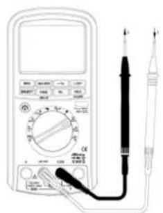
- Meten van DC mA/AC mA/DC mA + AC mA
Stroombereik: 1μA\~500mA
| Bereik | Gevoeligheid |
| 500mV | 100mV |
| 5V | 0.5V |
| 50V | 4V |
| 500V | 40V |
| 1000V | 400V |
| 5000μA | 1mA |
| 500mA | 100mA |
(sinusgolf)

- Mesure de CC mA/CA mA/CC mA + CA mA

| Gamme Sensibilité (onde sinusoïdale) | |
| 500mV | 100mV |
| 5V | 0.5V |
| 50V | 4V |
| 500V | 40V |
| 1000V | 400V |
| 5000μA | 1mA |
| 500mA | 100mA |
| Range | Résolution | Précision |
| 50nF | 0.01nF | ± (1% + 5) |
| 500nF | 0.1nF | |
| 5μF | 1nF | |
| 50μF | 10nF | |
| 500μF | 0.1μF | ± (2% + 5) |
| 5000μF | 1μF |


• Medir CC mA/CA mA/CC mA + CA mA
• Medir CC A/CA A/CC A + CA A
Rango de corriente: 0.1mA\~10A

| Rango Sensibilidad (onda sinusoidal) | |
| 500mV | 100mV |
| 5V | 0.5V |
| 50V | 4V |
| 500V | 40V |
| 1000V | 400V |
| 5000μA | 1mA |
| 500mA | 100mA |
Corriente CA/CC + CA
| Rango | Resolución | Precisión Caída de tensión | |||
| 40Hz~1kHz | 1kHz~10kHz | 10kHz~20kHz | |||
| 500μA 0.01μA | ± (0.75% + 20) ± (1% + 20) | ± (2% + 20) | 102μV/μA | ||
| 5000μA 0.1μA | ± (0.75% + 10) | ± (1% + 10) ± (2% + 10) | |||
| 50mA | 1μA | ± (0.75% + 20) ± (1% + 20) | ± (2% + 20) | 1.5mA/mA | |
| 500mA | 10μA | ± (0.75% + 10) ± (1% + 10) | ± (2% + 10) | ||
| 5A | 0.1mA | ± (0.75% + 20) | ± (1.5% + 20) | ± (5% + 20) | 30mV/A |
| 10A | 1mA | ± (1.0% + 10) | ± (1.5% + 10) | no especificada | |


• DC mA/AC mA/DC mA + AC mA-Messungen
| Bereich | Empfindlichkeit |
| 500mV | 100mV |
| 5V | 0.5V |
| 50V | 4V |
| 500V | 40V |
| 1000V | 400V |
| 5000μA | 1mA |
| 500mA | 100mA |
(Sinuswelle)
natural_image
Line drawing of a multimeter connected to a probe and a terminal ruler (no text or symbols visible)
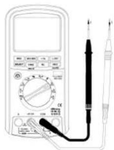
• Pomiar DC mA/AC mA/DC mA + AC mA
Zakres prądu : 1μA\~500mA

Above accuracies for film capacitors or better guaranteed within the full range.
Dioda


- DVM2000 – HIGH-ACCURACY TRUE RMS MULTIMETER - 50000 COUNTS
- Introduction
- To all residents of the European Union
- Important environmental information about this product
- Safety Instructions
- Description
- a. Multimeter
- b. LCD Display
- Operation
- - Backlight
- - Data Hold
- - Automatic Shutoff
- • Relative Value Measurement
- • Maximum/Minimum Value Measurement
- - Connecting the Multimeter to a Computer
- • ACV/dBm Measurements
- • DCV/DCV + ACV Measurements
- • DC mV/AC mV/DC mV + AC mV Measurements
- - Logic Frequency/Duty Cycle Measurements
- • Diode Measurements
- • Resistance/Continuity Measurements
- - Capacitance Measurements
- • DC μA/AC μA/DC μA + AC μA Measurements
- • DC mA/AC mA/DC mA + AC mA Measurements
- • DC A/AC A/DC A + AC A Measurements
- • Linear Frequency Measurements
- Cleaning and Maintenance
- Battery Replacement
- Fuse Replacement
- Meter Calibration
- Other
- Technical Specifications
- DVM2000 - TRUE RMS-MULTIMETER - ZEER NAUWKEURIG - 50000 COUNTS
- Inleiding
- • Medir CC mA/CA mA/CC mA + CA mA
- • Medir CC A/CA A/CC A + CA A
- • Pomiar DC mA/AC mA/DC mA + AC mA
Brand : VELLEMAN
Model : DVM2000
Category : Multimeter