
GT5OC6 - Boiler GORENJE - Free user manual and instructions
Find the device manual for free GT5OC6 GORENJE in PDF.


| Product type | Condensing boiler |
| Brand | Gorenje |
| Model | GT5OC6 |
| Dimensions (W x H x D) | 400 x 700 x 300 mm |
| Weight | 30 kg |
| Fuel | Natural gas / Propane |
| Nominal thermal output | 24 kW |
| Power range | 5.0 - 24.0 kW |
| Seasonal energy efficiency | 92 % |
| Energy efficiency class | A |
| Max. heating temperature | 80 °C |
| Max. DHW temperature | 60 °C |
| Domestic hot water flow rate | 11 l/min |
| Max. operating pressure | 3 bars |
| Flue type | Room-sealed (balanced flue) |
| Electrical connection | 230 V / 50 Hz |
| Power consumption | 150 W |
| Protection rating | IPX4 |
| Integrated hot water tank | No |
| Maintenance and cleaning | Annual cleaning of burners and heat exchanger by a professional |
| Safety | Overheat protection, frost protection, low water protection, gas shut-off |
| Spare parts and repairability | Parts available on request, repairability index: 8/10 |
| General information | User and installation manual included, 72 pages |
Frequently Asked Questions - GT5OC6 GORENJE
User questions about GT5OC6 GORENJE
0 question about this device. Answer the ones you know or ask your own.
Ask a new question about this device
Download the instructions for your Boiler in PDF format for free! Find your manual GT5OC6 - GORENJE and take your electronic device back in hand. On this page are published all the documents necessary for the use of your device. GT5OC6 by GORENJE.
USER MANUAL GT5OC6 GORENJE
GT 5
Instructions for Use 16
Upute za upotrebu 20
Návod k obsluze 24
a) Izvijač vstavite v režo 1 in odstranite pokrov gumba 2,
b) Omejilec gumba 3 nato poljubno nastavite na željeno temperaturo:
C - 35 °C
B - 45 °C
A-55°C
O - 75 °C
Dear customer, we thank you for purchasing our product.
PLEASE READ THE INSTRUCTIONS THOROUGHLY PRIOR TO THE INSTALLATION AND FIRST OPERATION OF THE WATER HEATER THIS APPLIANCE IS NOT INTENDED FOR USE BY PERSONS (INCLUDING CHILDREN) WITH REDUCED PHYSICAL, SENSORY OR MENTAL CAPABILITIES, OR LACK OF EXPERIENCE AND KNOWLEDGE, UNLESS THEY HAVE BEEN GIVEN SUPERVISION OR INSTRUCTION CONCERNING USE OF THE APPLIANCE BY PERSON RESPONSIBLE FOR THEIR SAFETY.
CHILDREN SHOULD BE SUPERVISED TO ENSURE THAT THEY DO NOT PLAY WITH THE APPLIANCE.
This water heater has been manufactured in compliance with the relevant standards and tested by the relevant authorities as indicated by the Safety Certificate and the Electromagnetic Compatibility Certificate. Its basic technical properties are stated upon the nameplate, glued between the connection pipes. The water heater may be connected to water and electric power supply only by a qualified specialist. The reach in its inside due to the repair or removal of limestone and checking and replacement of anti-corrosion protection anode may be performed only by an authorised service workshop.
INSTALLATION
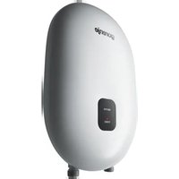
The water heater should be installed in a room protected from the onset of freezing conditions and located as close as possible to the points of use. Given your particular requirements there are several models of heaters to choose from: GT 5 O are suitable for installation above the basin/sink, while GT 5 U may be installed below the basin/sink.
TECHNICAL CHARACTERISTICS
| Type GT5O GT5U | ||
| Nominal capacity [I] 5 | ||
| Nominal pressure [MPa] 0,6 | ||
| Mass / filled with water [kg] 7/12 | ||
| Anticorrosion protection of the tank Enamelled | /Mg anode | |
| Nominal power [W] 2000 | ||
| Nominal voltage [V ~] | 230 | |
| Heating time to 75°C 1) [min] | 11 | |
| Quantity of mixed water at 40°C [I] 9 | ||
| Power consumption 2) [kWh/24h] | 0,25 | |
1) Time required for the electrical heating element to heat the entire tank volume, at the water supply temperature of 10° C.
2) Power consumption required for the temperature of water in the water heater to be maintained at 65° C, at the room temperature of 20° C, determined in accordance with the DIN 44532 standard.
Dimensions of the water heater for installation and connection [mm]

Installation above the basin/sink Installation below the basin/sink
CONNECTION TO THE WATER SUPPLY
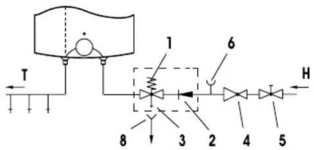
Inlet and outlet of water are on the water heater pipes marked with colour. The supply of cold water is marked with blue, the outlet of warm water is marked with red.
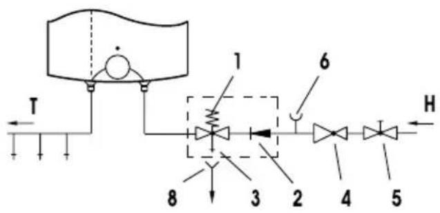
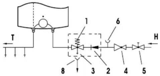
The water heater can be connected to the water supply in two manners. Closed pressure system of connection enables the outlet of water on several outlet spots, non-pressure system enables only one outlet point. With regard to the system of connection chosen, also the suitable mixing taps must be purchased.
By open non-pressure system it must before the water heater a non-return valve be built-in preventing the running of water of the tank if in the network the water runs short. By this system of connection, the cross-flow mixing tap must be used. In the water heater, due to the heating the volume of water is increasing, which causes the dropping of water of the mixing tap pipe. By strong squeezing of knob of the mixing tap the dropping of water can not be prevented, but the mixing tap can only be damaged. By closed pressure system of connection on the outlet spots the pressure mixing tap must be used. For safety reasons the supply pipe must be fitted with a return safety valve or alternatively, a valve of the safety class that prevents the pressure in the tank from exceeding the nominal pressure by more than 0.1 MPa.
By heating of water in the water heater the pressure of water in the tank is increasing to the limit which is adjusted in the safety valve. Because the return of water back to the water supply is prevented, dropping of water from outlet opening of the safety valve can occur. The dropping water may be let to the outlet over an intercepting accessory which is placed under the safety valve. In order to do this you should first unscrew the protective cover off the water heater.
Open-circuit (gravity) system Closed-circuit (pressure) system
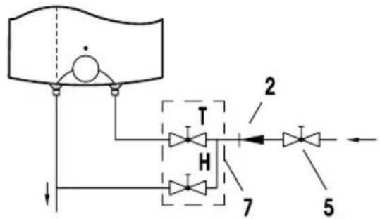
Installation above the basin/sink

Installation above the basin/sink
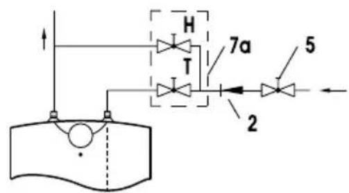

Installation below the basin/sink Installation below the basin/sink
Legend:
1 - Safety valve 7 - Mixer tap - installation above the basin/sink
2 - Non-return valve 7a - Mixer tap - installation below the basin/sink
3 - Test valve 8 - Funnel outlet to the drain
4 - Pressure-reducing valve
5 - Stop valve H - Cold water
6 - Testing piece T - Hot water
The stop valve must not be installed between the water heater and safety valve, as this would disable the safety valve.
The water heater may be connected to the water supply system without the pressure-reducing valve, provided the supply mains pressure is less than 0.5 MPa. The water heater must be filled with water prior to being connected to the power supply. The hot water tap must be open during the initial filling of the tank. The tank is full when the water starts flowing through the tap and into the sink.
POWER CONNECTION
The water heater shall be connected to the power supply by an electrical cable fitted with a plug. Should the existing cable replaced by a new, longer cable, the new cable should be connected to the lead and the wires screwed to the connectors. In this case the water heater should first be disconnected from the power supply. For safety reasons a switch should be installed on the lead connecting the heater to the power grid, i.e. a switch disconnecting both power supply poles with the minimum of 3 mm distance between the open contacts.
The water heater must be connected to the power supply in accordance with the requirements set out in the relevant standards applying to the electrical installations.
WARNING: The appliance must be disconnected from the power supply prior to doing anything that requires you to open the body of the water heater!
Legend:
1 - Thermostat
2 - Thermal fuse
3 - Heating element
4 - Light indicator
5 - Connector
L - Phase lead
N - Neutral lead
± - Earth lead

Electrical installation drawing
The water heater is ready for use once it has been connected to water and power. By turning the thermostat knob on the front side of the protective cover, water temperature can be set between 25 °C, position " ●" and 75 °C, position " ●". We recommend that the knob be set to position " e " as this ensures the most economic operation of the water heater. This way the water temperature is maintained at 55 °C. The operation of the heater at this temperature level also results in reduced build-up of calcium and lime, as well as reduced heat loss than is the case at higher temperatures. Due to safety reasons you can optionally set the highest temperature value of water in the heater. Proceed as follows:

a) Insert screwdriver in slot 1 and remove button cover 2, b) Set knob limiter 3 to any desired temperature value,
C - 35 °C
B - 45 °C
A - 55 °C
O - 75 °C
c) Replace knob cover 2 to the knob.
The operation of the heating element is indicated by the light indicator that stays on until the temperature in the tank has reached the set level or until the heater has been deliberately switched off. When the water heater is not in use for longer periods of time, it should be protected from freezing by setting the temperature to "*". Do not disconnect the power. Thus the temperature of the water in the tank is maintained at about 9 °C. Should you choose to disconnect the power, the water heater should be thoroughly drained before the onset of freezing conditions. The exterior of the water heater may be cleaned with a mild detergent solution. Do not use solvents and abrasive cleaners.
Regular preventive maintenance inspections ensure faultless performance and long life of your heater. The first of these inspections should be carried out by the authorised maintenance service provider about two years from the date of installation in order to check the wear of the protective anticorrosion anode and remove any build-up of calcium and lime as required. The build-up of calcium and lime in the water heater depends on the quality, quantity and temperature of water flowing through the heater. The maintenance service provider shall also issue a condition report and recommend the approximate date of the next inspection.
In the event of the heater breaking down, you are kindly requested to contact the authorised maintenance service provider located closest to you. Please do not attempt to carry out any repairs yourself.
a) Odvijač stavite u otvor 1 i odstranite poklopac gumba 2,
b) Graničnik gumba 3 zatim proizvoljno podesite na željenu temperaturu,
C - 35 °C
B - 45 °C
A - 55 °C
O - 75 °C
c) Poklopac gumba 2 ponovno stavite na kućište gumba.
Монтаж над мивка

Varianta "deasupra chiuvetei"
Varianta "deasupra chiuvetei"

Varianta "sub chiuvetâ" Varianta "sub chiuvetâ"

Legenda:
Изведба над лавабо

Изведба над лавабо

a) Odvijač stavite u otvor 1 i odstranite poklopac gumba 2,
b) Graničnik gumba 3 zatim proizvoljno podesite na željenu temperaturu,
C - 35 °C
B - 45 °C
A-55°C
O - 75 °C
c) Poklopac gumba 2 ponovno stavite na kućište gumba.
Mbi vendin e harxhimit
Nën vendin e harxhimit

Mbi vendin e harxhimit Nën vendin e harxhimit

Legjenda:



- GT 5
- CHILDREN SHOULD BE SUPERVISED TO ENSURE THAT THEY DO NOT PLAY WITH THE APPLIANCE
- INSTALLATION
- CONNECTION TO THE WATER SUPPLY
- LEGEND
- THE STOP VALVE MUST NOT BE INSTALLED BETWEEN THE WATER HEATER AND SAFETY VALVE, AS THIS WOULD DISABLE THE SAFETY VALVE
- POWER CONNECTION
- WARNING: THE APPLIANCE MUST BE DISCONNECTED FROM THE POWER SUPPLY PRIOR TO DOING ANYTHING THAT REQUIRES YOU TO OPEN THE BODY OF THE WATER HEATER
- LEGENDA
- LEGJENDA
Brand : GORENJE
Model : GT5OC6
Category : Boiler