
Ultra-DI DI20 - Audio/video converter BEHRINGER - Free user manual and instructions
Find the device manual for free Ultra-DI DI20 BEHRINGER in PDF.


| Product type | Audio/Video Converter (DI Box) |
| Model | Ultra-DI DI20 |
| Brand | Behringer |
| Channels | 2 (Stereo) |
| Inputs | 2× 6.3 mm jack (balanced/unbalanced) |
| Outputs | 2× XLR (balanced) |
| Frequency response | 20 Hz – 20 kHz |
| Signal-to-noise ratio | > 100 dB |
| Total harmonic distortion | < 0.01 % |
| Ground lift switch | Yes |
| Pad (attenuation) | -20 dB |
| Mono/Stereo switch | Yes |
| Power supply | 9 V battery or phantom power (48 V) |
| Battery life | approx. 1000 hours (alkaline) |
| Housing material | Steel sheet, black powder-coated |
| Dimensions (W×H×D) | 125 × 70 × 120 mm |
| Weight | 0.5 kg |
| Cleaning | Wipe with a dry, lint-free cloth. Do not use liquids. |
| Safety instructions | Do not operate in humid environments. Do not insert objects into openings. |
| Spare parts / Repair | No user-serviceable parts. Repairs only by qualified personnel. |
Frequently Asked Questions - Ultra-DI DI20 BEHRINGER
User questions about Ultra-DI DI20 BEHRINGER
0 question about this device. Answer the ones you know or ask your own.
Ask a new question about this device
Download the instructions for your Audio/video converter in PDF format for free! Find your manual Ultra-DI DI20 - BEHRINGER and take your electronic device back in hand. On this page are published all the documents necessary for the use of your device. Ultra-DI DI20 by BEHRINGER.
USER MANUAL Ultra-DI DI20 BEHRINGER
1. Welcome to the Behringer Family!
On stage as well as in studios, it is sometimes advantageous to connect certain sound sources directly to the mixing console.
Since many instruments (keyboards, for example) don't have balanced outputs they require a DI-box. Sometimes, even guitars can't be directly connected to mixing consoles because their impedance is too high.
By using a DI-box, you can directly tap into a high-impedance, unbalanced signal—for example, a signal between a guitar and a guitar amplifier. From this point, you can feed this signal directly to a mixing console.
There are active and passive DI-boxes. A passive DI-box is more affordable, but its performance is dependent on the impedance of the device to which it is connected. When the impedance on the mixing console's end changes, so does the impedance at the input of the DI-box. Such DI-boxes only function properly when the connected impedance values are strictly specified (high at the input, low at the output). Active DI-boxes are not affected by these impedance considerations. The input impedance of the DI20 is extremely high, and it absolutely does not influence the signal flow through the DI-box. The output impedance is balanced and always very low, whereby the signal is far less prone to being affected by noise.
To prevent damaging your loudspeakers, first connect the DI-box and then hook up the respective channel. The same goes for alternating between battery and phantom power operating modes.
2. Controls

Fig. 2.1: Controls of the D120
1 CH. 1 IN input is used to connect unbalanced as well as balanced signal sources to channel 1.
2 CH.1 OUT is the balanced output at mic level for channel 1.
3 CH.2 IN input is used to connect unbalanced as well as balanced signal sources to channel 2. In Link mode (see 6) this connector functions as output and sends the signal directly from channel 1.
4 CH. 2 OUT is the balanced output at mic level for channel 2. In Link Mode (see 6) this connector sends the signal directly from channel 1.
5 The ATTENUATION dampening switch considerably increases the useful operating range of the DI20 from low signal levels of a high-impedence microphone or a guitar, all the way to the speaker connectors of a guitar amplifier (solid state). You can select between 20 and 40 dB worth of attenuation.
You should only use the ATTENUATION switch when your DI20 rather than the mixing console preamp begins distorting. Otherwise refrain from using this function to avoid excessive dampening.
6 The MODE switch lets you select the operating modes of the DI20. In the 2-CH mode, two independent signals can be connected to channels 1 and 2 respectively. In LINK mode the DI-box functions as a splitter: One signal can be fed to the channel 1 input and split into two balanced signals (at outputs 1 and 2) and an unbalanced signal at CH.1 OUT. The un-balanced signal can, for example, be connected to an additional amplifier.
When connecting a tube amplifier to the input of the DI20, please keep in mind that an appropriate load resistance (e.g. a loudspeaker) must be connected to the CH.1 OUT (LINK MODE) connector.
7 The BATTERY switch activates the battery powered mode. Set the battery operating mode to OFF when your DI20 is connected to phantom power. While setting it to OFF, brief whistling noise may occur. This is completely normal and needs no further attention. However, you should not change the battery switch when you have an amp connected. For battery operation, you'll only need a commercial 9 V battery of the 6LR61 type.
8
By using the GROUND switch, you can interrupt (LIFT) the grounding between the input and output. Depending on how other devices connected to your DI-box are grounded, ground loops can be eliminated.
◇
◇ Never connect pin 2 or pin 3 to pin 1! Never remove the screen protection on pin 1. Otherwise, you won't be able to run the DI20 on phantom power (for example, phantom power from a mixing console).
Battery compartment
To access the battery compartment, loosen the screw on the rear.
3. Connection Options 3.1 Connecting a (bass) guitar
![graph TD A["In"] --> B["Out"] B --> C["ULTRA-DI DI20"] C --> D["EUORACK UB2222FX-PRO"] D --> E["Link Out"] E --> F["Water Washing Machine"]](/content/2026/06/1281026/images/4311fedd5e8e7f42af4fb75ba80c7623ee0e47faac7988a0587b4a39703e18db.jpg)
Fig. 3.1: Guitar DI-box guitar amp/mixing console
This illustration shows the standard application of a DI-box. The signal is fed unbalanced to a guitar amp and balanced to a mixing console (LINK mode). This application has advantages when used with bass guitars, because very few microphones are able to pick up low frequencies at high levels.
3.2 Converting output signals of a keyboard, DJ-mixer, etc.
![graph TD A["PRO MIXER VMX200"] -->|L In| B["ULTRA-DI DI20"] A -->|R In| B B -->|Out| C["EURORACK UB2222FX-PRO"] B -->|Out| D["Mic In"]](/content/2026/06/1281026/images/f8d40152cb7a41c418b451875d47cc70cecdf7802f82d0a3a95771338f4003e8.jpg)
Fig. 3.2: DJ-mixer DJ-box mixing console
This configuration is recommended when using a DJ-mixer or another signal source, which sends an unbalanced line level signal. In addition, if you need a separate monitor signal, the line level signal can be sent to another amplifier.
4. Audio Connections
The Behringer ULTRA-DI DI20 features electronically servo-balanced standard inputs and outputs. The circuit design is equipped with automatic hum suppression for balanced signals and operates problem-free even at high levels. Externally induced mains hum is thus efficiently suppressed. The servo function automatically detects unbalanced pin connections and changes the nominal level internally by 6 dB so that there is no difference in level between input and output signals.
Balanced use with XLR connectors
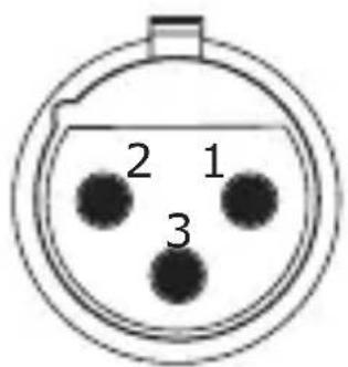
input

output
1 = ground/shield
2 = hot (+ve)
3 = cold (-ve)
For unbalanced use, pin 1 and pin 3 have to be bridged
Fig. 4.1: XLR connectors

Fig. 4.2: 1/4 " TS connector
Balanced 1/4 " TRS connector

For connection of balanced and unbalanced plugs, ring and sleeve have to be bridged at the stereo plug.
Fig. 4.3: 1/4'' TRS connector
5. Multilingual Documentation

The following versions of this user's manual can be downloaded free of charge at http://behringer.com: German, French, Spanish, Italian, Dutch, Finnish, Swedish, Danish, Portuguese and Greek.
EN Safety Instruction
- Read these instructions.
- Keep these instructions.
- Heed all warnings.
- Follow all instructions.
- Do not use this apparatus near water.
-
Clean only with dry cloth.
-
Do not block any ventilation openings. Install in accordance with the manufacturer's instructions.
-
Do not install near any heat sources such as radiators, heat registers, stoves, or other apparatus (including amplifiers) that produce heat.
-
Use only attachments/accessories specified by the manufacturer.

- Use only with the cart, stand, tripod, bracket, or table specified by the manufacturer, or sold with the apparatus. When a cart is used, use caution when moving the cart/apparatus combination to avoid injury from tip-over.

-
Correct disposal of this product: This symbol indicates that this product must not be disposed of with household waste, according to the WEEE Directive (2012/19/EU) and your national law. This product should be taken to a collection center licensed for the recycling of waste electrical and electronic equipment (EEE). The mishandling of this type of waste could have a possible negative impact on the environment and human health due to potentially hazardous substances that are generally associated with EEE. At the same time, your cooperation in the correct disposal of this product will contribute to the efficient use of natural resources. For more information about where you can take your waste equipment for recycling, please contact your local city office, or your household waste collection service.
-
Do not install in a confined space, such as a book case or similar unit.
- Do not place naked flame sources, such as lighted candles, on the apparatus.
Balanced use with XLR connectors

input

output
1 = ground/shield
2 = hot (+ve)
3 = cold (-ve)
For unbalanced use, pin 1 and pin 3 have to be bridged
Fig. 4.1: Conectores XLR
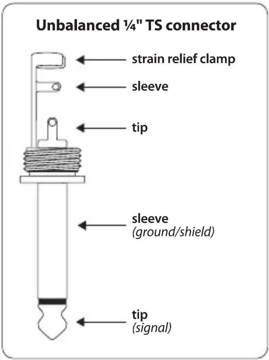
Fig. 4.2: Jack estéreo de 6,3 mm
Balanced 1/4 " TRS connector

For connection of balanced and unbalanced plugs, ring and sleeve have to be bridged at the stereo plug.
Fig. 4.3: Jack mono de 6,3 mm
Balanced use with XLR connectors

input

output
1 = ground/shield
2 = hot (+ve)
3 = cold (-ve)
For unbalanced use, pin 1 and pin 3 have to be bridged
Balanced 1/4 " TRS connector

For connection of balanced and unbalanced plugs, ring and sleeve have to be bridged at the stereo plug.
Balanced use with XLR connectors

input

output
1 = ground/shield
2 = hot (+ve)
3 = cold (-ve)
For unbalanced use, pin 1 and pin 3 have to be bridged
Balanced 1/4 " TRS connector

For connection of balanced and unbalanced plugs, ring and sleeve have to be bridged at the stereo plug.
Abb. 4.3: 6,3 mm-Stereoklinkenstecker
Balanced use with XLR connectors

input

output
1 = ground/shield
2 = hot (+ve)
3 = cold (-ve)
For unbalanced use, pin 1 and pin 3 have to be bridged
Fig. 4.2: Ficha jack mono de 6,3 mm
Balanced 1/4 " TRS connector

For connection of balanced and unbalanced plugs, ring and sleeve have to be bridged at the stereo plug.
Fig. 4.3: Ficha jack stéreo de 6,3 mm
Balanced use with XLR connectors
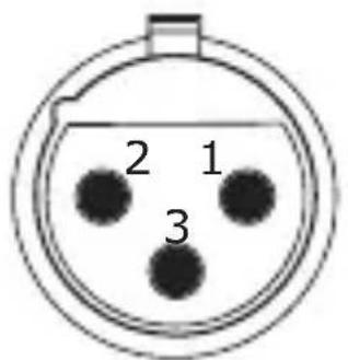
input
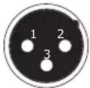
output
1 = ground/shield
2 = hot (+ve)
3 = cold (-ve)
For unbalanced use, pin 1 and pin 3 have to be bridged
Fig. 4.1: XLR connectors

Fig. 4.2: 1/4 " TS connector
Balanced 1/4 " TRS connector

For connection of balanced and unbalanced plugs, ring and sleeve have to be bridged at the stereo plug.
Fig. 4.3: 1/4'' TRS connector
Balanced use with XLR connectors
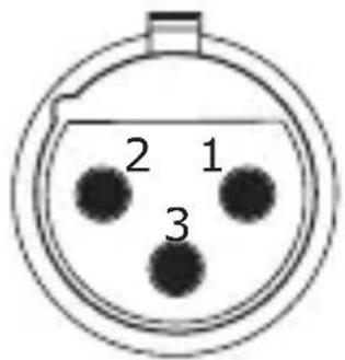
input

output
1 = ground/shield
2 = hot (+ve)
3 = cold (-ve)
For unbalanced use, pin 1 and pin 3 have to be bridged
Afb. 4.1: XLR connectoren

Afb. 4.2: ¼" TS connectoren
Balanced 1/4 " TRS connector

For connection of balanced and unbalanced plugs, ring and sleeve have to be bridged at the stereo plug.
Afb. 4.3: ¼" TRS connectoren
5. Meertalige documentatie
Balanced use with XLR connectors

input

output
1 = ground/shield
2 = hot (+ve)
3 = cold (-ve)
For unbalanced use, pin 1 and pin 3 have to be bridged
Balanced 1/4" TRS connector

For connection of balanced and unbalanced plugs, ring and sleeve have to be bridged at the stereo plug.
Bild 4.3: ¼" TRS kontakter
Balanced use with XLR connectors

input

output
1 = ground/shield
2 = hot (+ve)
3 = cold (-ve)
For unbalanced use, pin 1 and pin 3 have to be bridged

Balanced 1/4 " TRS connector

For connection of balanced and unbalanced plugs, ring and sleeve have to be bridged at the stereo plug.
| Frequency response 10 Hz to 70 kHz (-3 dB) |
| Noise 100 dBu |
| Distortion < 0.014% (1 kHz, 0 dBu in) |
| Input resistance >250 kΩ |
| Connection impedance >600 Ω |
| Input 1⁄4" mono jack |
| Output XLR balanced |
| Max. input level +12/+32/+52 dBu |
| Phantom power 18 V DC to 48 V DC |
| Battery power 9 V 6LR91 |
| Dimensions approx. 6 x 5 x 2 3/8"approx. 150 x 130 x 60 mm |
| Weight approx. 240 g |
Behringer is constantly striving to maintain the highest professional standards. As a result of these efforts, modifications may be made from time to time to existing products without prior notice.
Specifications and appearance may therefore differ from those listed or shown.
LEGAL DISCLAIMER
Music Tribe accepts no liability for any loss which may be suffered by any person who relies either wholly or in part upon any description, photograph, or statement contained herein. Technical specifications, appearances and other information are subject to change without notice. All trademarks are the property of their respective owners. Midas, Klark Teknik, Lab Gruppen, Lake, Tannoy, Turbosound, TC Electronic, TC Helicon, Behringer, Bugera, Aston Microphones and Coolaudio are trademarks or registered trademarks of Music Tribe Global Brands Ltd. © Music Tribe Global Brands Ltd. 2023 All rights reserved.
LIMITED WARRANTY
For the applicable warranty terms and conditions and additional information regarding Music Tribe's Limited Warranty, please see complete details online at community.musictribe.com/pages/support#warranty.
NEGACIÓN LEGAL
BESCHRÄNKTE GARANTIE
Hereby, Music Tribe declares that this product is in compliance with Directive 2014/30/EU, Directive 2011/65/EU and Amendment 2015/863/EU, Directive 2012/19/EU, Regulation 519/2012 REACH SVHC and Directive 1907/2006/EC.
Full text of EU DoC is available at https://community.musictribe.com/
EU Representative: Music Tribe Brands DK A/S
Address: Ib Spang Olsens Gade 17, DK - 8200 Aarhus N, Denmark
We Hear You


- WELCOME TO THE BEHRINGER FAMILY
- CONTROLS
- BATTERY COMPARTMENT
- CONNECTION OPTIONS 3.1 CONNECTING A (BASS) GUITAR
- 3.2 CONVERTING OUTPUT SIGNALS OF A KEYBOARD, DJ-MIXER, ETC
- AUDIO CONNECTIONS
- MULTILINGUAL DOCUMENTATION
- EN SAFETY INSTRUCTION
- MEERTALIGE DOCUMENTATIE
- LEGAL DISCLAIMER
- LIMITED WARRANTY
- NEGACIÓN LEGAL
- BESCHRÄNKTE GARANTIE
Brand : BEHRINGER
Model : Ultra-DI DI20
Category : Audio/video converter