
SRC2496 - Audio/video converter BEHRINGER - Free user manual and instructions
Find the device manual for free SRC2496 BEHRINGER in PDF.

| Product Type | Audio/Video Converter (Sample Rate Converter & A/D-D/A Converter) |
| Brand | Behringer |
| Model | ULTRAMATCH PRO SRC2496 |
| A/D Conversion | 24-bit/96 kHz, 128/64 times oversampling delta-sigma AKM converter, input level -4 dBu to +22 dBu for 0 dBFS, S/N ratio >105 dB |
| D/A Conversion | 24-bit/96 kHz, 128 times oversampling delta-sigma AKM converter, output level +16 dBu @ 0 dBFS, S/N ratio >108 dB |
| Sample Rate Conversion | Real-time, 24-bit precision, accepts 31 Hz to 100 kHz, outputs 32, 44.1, 48, 88.2, 96 kHz |
| Digital Inputs | 3: XLR (110 ohms, transformer-balanced), RCA (75 ohms, transformer-balanced), Toslink optical |
| Digital Outputs | 3: XLR (110 ohms balanced, 3.5 Vpp), RCA (75 ohms, 0.5 Vpp), Toslink optical |
| Analog Inputs | 2 (stereo) XLR balanced, 20 kohms, adjustable input level |
| Analog Outputs | 2 (stereo) XLR balanced, 160 ohms, +16 dBu @ 0 dBFS |
| Headphone Output | 1/4" TRS, adjustable volume |
| Synchronization | Internal (32/44.1/48/88.2/96 kHz), external wordclock via BNC (50 kohms), or digital input PLL (31-100 kHz) |
| Word Length | Selectable: 16, 20, 24 bits; dither function |
| Emphasis | Adjustable emphasis bit (50/15 μs) on output |
| Copy Protection | SCMS control: copy permit/original status adjustable (S/PDIF only) |
| Power Supply | 120/230 V~, 50-60 Hz, 15 W, IEC connector, fuse: T 250 mA H 250 V (100-120 V) / T 125 mA H 250 V (200-240 V) |
| Dimensions | 44.5 x 483 x 217 mm (1.75 x 19 x 8.54 inches), 1U rackmount |
| Weight | 2.3 kg (5.06 lbs) unit, 3.4 kg (7.48 lbs) shipping |
| Jitter Suppression | Input jitter tolerated >40 ns, internal jitter at input <2 ns, external sync jitter <20 ns (10 ns typical) |
| Format Support | AES/EBU and S/PDIF (professional and consumer) on all digital I/O |
Frequently Asked Questions - SRC2496 BEHRINGER
User questions about SRC2496 BEHRINGER
0 question about this device. Answer the ones you know or ask your own.
Ask a new question about this device
Download the instructions for your Audio/video converter in PDF format for free! Find your manual SRC2496 - BEHRINGER and take your electronic device back in hand. On this page are published all the documents necessary for the use of your device. SRC2496 by BEHRINGER.
USER MANUAL SRC2496 BEHRINGER
EN
User Manual
natural_image
Black-and-white collage of eight music events including a singer, guitar, keyboard, stage with spotlights, and a band performing on stage (no visible text or symbols)ULTRAMATCH PRO SRC2496
Audiophile 24-Bit/96 kHz A/D-D/A & Sample Rate Converter
EN
Table of Contents
Important Safety Instructions .... 3
Legal Disclaimer 3
Limited warranty....3
1. Introduction....4
1.1 The design concept......4
1.2 Before you begin 4
2. Control Elements......4
2.1 Front panel of the
ULTRAMATCH PRO SRC2496....4
2.2 Rear panel of the ULTRAMATCH PRO 6
3. Applications ....7
3.1 A/D and D/A conversion with the ULTRAMATCH PRO 7
3.2 Sample rate conversion....9
3.3 Removing copy protect information....9
3.4 Noise reduction with emphasis....9
3.5 Line booster, signal refresher....10
3.6 Correcting incorrect sample rates.... 10
3.7 Vari-speed application....10
3.8 Format converter....10
3.9 Format interface....10
3.10 Patchbay/splitter....10
4. Technical Background ...... 10
4.1 A short digression into digital sample rate conversion 10
4.2 AES/EBU and S/PDIF standards 11
5. Installation 11
5.1 General connection notes.... 11
5.2 Analog inputs and outputs.... 11
5.3 Digital inputs and outputs.... 12
5.4 Headphones output....13
6. Specifications.... 13
EN
Important Safety Instructions
CAUTION
RISK OF ELECTRIC SHOCK!
DO NOT OPEN!
ATTENTION
RISQUE D'ÉLECTROCUTION !
NE PAS OUVRIR !

Terminals marked with this symbol carry electrical current of sufficient magnitude to constitute risk of electric shock.
Use only high-quality professional speaker cables with 14 " TS or twist-locking plugs pre-installed. All other installation or modification should be performed only by qualified personnel.
This symbol, wherever it appears, alerts you to the presence of uninsulated dangerous voltage inside the
enclosure - voltage that may be sufficient to constitute a risk of shock.

This symbol, wherever it appears, alerts you to important operating and maintenance instructions in the
accompanying literature. Please read the manual.

Caution
To reduce the risk of electric shock, do not remove the top cover (or the rear section).
No user serviceable parts inside. Refer servicing to qualified personnel.

Caution
To reduce the risk of fire or electric shock, do not expose this appliance to rain and
moisture. The apparatus shall not be exposed to dripping or splashing liquids and no objects filled with liquids, such as vases, shall be placed on the apparatus.

Caution
These service instructions are for use by qualified service personnel only.
To reduce the risk of electric shock do not perform any servicing other than that contained in the operation instructions. Repairs have to be performed by qualified service personnel.
- Read these instructions.
- Keep these instructions.
- Heed all warnings.
- Follow all instructions.
- Do not use this apparatus near water.
- Clean only with dry cloth.
- Do not block any ventilation openings. Install in accordance with the manufacturer's instructions.
-
Do not install near any heat sources such as radiators, heat registers, stoves, or other apparatus (including amplifiers) that produce heat.
-
Do not defeat the safety purpose of the polarized or grounding-type plug. A polarized plug has two blades with one wider than the other. A grounding-type plug has two blades and a third grounding prong. The wide blade or the third prong are provided for your safety. If the provided plug does not fit into your outlet, consult an electrician for replacement of the obsolete outlet.
- Protect the power cord from being walked on or pinched particularly at plugs, convenience receptacles, and the point where they exit from the apparatus.
- Use only attachments/accessories specified by the manufacturer.

natural_image
Silhouette of a person pushing a cart with a ladder, enclosed in a circular frame (no text or symbols)- Use only with the cart, stand, tripod, bracket, or table specified by the manufacturer, or sold with the apparatus. When a cart is used, use caution when moving the cart/apparatus combination to avoid
injury from tip-over.
- Unplug this apparatus during lightning storms or when unused for long periods of time.
- Refer all servicing to qualified service personnel. Servicing is required when the apparatus has been damaged in any way, such as power supply cord or plug is damaged, liquid has been spilled or objects have fallen into the apparatus, the apparatus has been exposed to rain or moisture, does not operate normally, or has been dropped.
- The apparatus shall be connected to a MAINS socket outlet with a protective earthing connection.
- Where the MAINS plug or an appliance coupler is used as the disconnect device, the disconnect device shall remain readily operable.

LEGAL DISCLAIMER
TECHNICAL SPECIFICATIONS AND APPEARANCES ARE SUBJECT TO CHANGE WITHOUT NOTICE AND ACCURACY IS NOT GUARANTEED. BEHRINGER, KLARK TEKNIK, MIDAS, BUGERA, AND TURBOSOUND ARE PART OF THE MUSIC GROUP (MUSIC-GROUP.COM). ALL TRADEMARKS ARE THE PROPERTY OF THEIR RESPECTIVE OWNERS. MUSIC GROUP ACCEPTS NO LIABILITY FOR ANY LOSS WHICH MAY BE SUFFERED BY ANY PERSON WHO RELIES EITHER WHOLLY OR IN PART UPON ANY DESCRIPTION, PHOTOGRAPH OR STATEMENT CONTAINED HEREIN. COLORS AND SPECIFICATIONS MAY VARY FROM ACTUAL PRODUCT. MUSIC GROUP PRODUCTS ARE SOLD THROUGH AUTHORIZED FULLFILLERS AND RESELLERS ONLY. FULLFILLERS AND RESELLERS ARE NOT AGENTS OF MUSIC GROUP AND HAVE ABSOLUTELY NO AUTHORITY
TO BIND MUSIC GROUP BY ANY EXPRESS OR IMPLIED UNDERTAKING OR REPRESENTATION. THIS MANUAL IS COPYRIGHTED. NO PART OF THIS MANUAL MAY BE REPRODUCED OR TRANSMITTED IN ANY FORM OR BY ANY MEANS, ELECTRONIC OR MECHANICAL, INCLUDING PHOTOCOPYING AND RECORDING OF ANY KIND, FOR ANY PURPOSE, WITHOUT THE EXPRESS WRITTEN PERMISSION OF MUSIC GROUP IP LTD.
ALL RIGHTS RESERVED.
© 2013 MUSIC Group IP Ltd.
Trident Chambers, Wickhams Cay, P.O. Box 146, Road Town, Tortola, British Virgin Islands
LIMITED WARRANTY
For the applicable warranty terms and conditions and additional information regarding MUSIC Group's Limited Warranty, please see complete details online at www.music-group.com/warranty.
EN
1. Introduction
The BEHRINGER ULTRAMATCH PRO is a fully digital signal processor integrating 24-bit A/D and D/A converters. With its wide range of features, it provides a powerful state-of-the-art interface between the physical reality of music and its recording in digital form. To retain the true authenticity of your music, we not only developed a strong link between analog recording technology and the huge variety of signal processing possibilities available in the digital world, but also designed the ULTRAMATCH PRO SRC2496 to function as a universal inter-face between the various digital formats and sampling rates.
Thus, incompatibilities between different equipment with regard to modified connectors, transmitted signals and applied standards are definitely a thing of the past.
This manual first describes the terminology used, so that you can fully understand the SRC2496 and its functions. Please read the manual carefully and keep it for future reference.
1.1 The design concept
The philosophy behind BEHRINGER products guarantees no-compromise circuit design and the best choice of components. We only use low-tolerance resistors and capacitors, high-grade switches and buttons as well as other select components to make sure that you can fully benefit from state-of-the-art 24-bit/96 kHz technology with regard to low noise and high dynamics. With the ULTRAMATCH PRO you have purchased some cutting-edge technology. Today, a lot of hi-fi equipment is already equipped with a digital interface, so the SCR2496 can not only be used as a high-end A/D and D/A converter in your studio, but also raises your home hi-fi system to a new level in terms of dynamics, low distortion and definition. It is thus possible to replace one of the weak points in the signal chain with an absolutely powerful unit.
The SRC2496 provides you with the functionality of a first-class A/D and D/A converter, an outstanding sampling rate converter and a digital patchbay. Additionally, it can be deployed as a format converter, to set or remove copy bits, and as a signal refresher—but is still easy to operate.
The front panel of your ULTRAMATCH RO features a functional and easily understandable layout. On the left-hand half of the panel you will find the monitor (left) and input sections (right); the right-hand half includes the mode (left) and output sections (right). Just imagine the signal passing through the unit from left to right and the design logic becomes clear.
The monitor section enables you to monitor analog input/output signals. The level meter reads the analog input level and allows you to adjust it optimally. The status LEDs in the input section make it easy to check which type of digital signal (AES/EBU or S/PDIF) is being received and also display its sampling rate. Since the ULTRAMATCH PRO is automatically synchronized to any input signals within a range from 31 Hz to 100 kHz, there is no need for dedicated sampling rate selector switches on the input side.
In the mode section you can see which of the SRC2496's two basic functions (A/D and D/A converter or sampling rate converter) is currently active. Select the function of your choice at the touch of a button. The output section gives you the buttons and displays to adjust a variety of parameters for the digital output signal.
The ULTRAMATCH PRO stores the last setting made before power-down, so you can continue from where you stopped when you turn the unit back on again.
In a later section of this manual we will give you a detailed description of how you can use your ULTRAMATCH PRO in various applications.
1.2 Before you begin
Your ULTRAMATCH PRO was carefully packed at the factory and the packaging is designed to protect the unit from rough handling. Nevertheless, we recommend that you carefully examine the packaging and its contents for any signs of physical damage which may have occurred during transit.
If the unit is damaged, please do NOT return it to BEHRINGER, but notify your dealer and the shipping company immediately, otherwise claims for damage or replacement may not be granted. Shipping claims must be made by the consignee.
The BEHRINGER ULTRAMATCH PRO requires one rack unit for installation in a 19" rack. Please allow for an additional 4" of rack depth for the rear panel connectors.
For rack mounting, please use M6 metal nuts and bolts.
Be sure that there is enough air space around the unit for cooling. For example, to avoid overheating, do not place the ULTRAMATCH PRO on power amps.
Before you connect your ULTRAMATCH PRO to the mains, please make sure that your local voltage matches the supply voltage required by the unit!
The fuse holder at the AC power connector has 3 triangular markings. Two of these three triangles will be aligned with one another. The ULTRAMATCH PRO is set to the voltage shown next to these markings and can be switched over by twisting the fuse holder by 180°. IMPORTANT: This does not apply to export models designed exclusively for 120 V operation!
If you set the unit to a different mains voltage, be sure to use a fuse of the correct type and rating! In chapter 6 "Specifications" you will find the matching fuse type for your local mains voltage.
The mains connection is made by using the enclosed power cord and a standard IEC receptacle. It meets all of the international safety certification requirements.
Please make sure that all units have a proper ground connection. For your own safety, never remove or disable the ground conductor of the unit or of the AC power cord.
Please ensure that only qualified persons install and operate the SRC2496. During installation and operation the user must have sufficient electrical contact to earth. Electrostatic discharges might affect the operation of the unit.
2. Control Elements
2.1 Front panel of the ULTRAMATCH PRO SRC2496
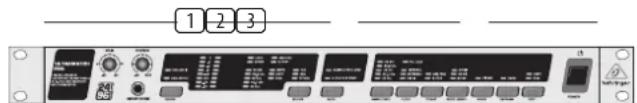
Fig. 2.1: Front panel control elements
Monitor and input sections. The monitor section enables you to adjust the signal level applied to the analog input and features a controllable headphone connector. A clearly structured LED array provides you with detailed information on the various parameters of the digital input signal.
2 Mode section. Here, you can determine whether your ULTRAMATCH PRO is working as a sampling rate converter or A/D-D/A converter.
3 Output section. The buttons in the output section allow you to tailor the output signal to meet your requirements.
Similarly to the input section, the display provides you with all the information on the output signal.
2.1.1 Monitor and input sections
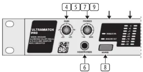
Fig. 2.2: Input section control elements
4 Use the GAIN control to adapt the signal level perfectly to the circuitry of your ULTRAMATCH PRO. The level should be as high as possible, but the 0 dB LED should only light up occasionally or never at all to avoid distortion.
5 The PHONES control governs the headphone volume. You can monitor either the analog output or input by setting the SOURCE switch accordingly. The analog output always provides the signal applied to the selected digital input, so this signal can be monitored with the headphones, too.
When the ULTRAMATCH PRO operates as an A/D-D/A converter, the digital input signal is applied to the analog output only in DIG IN mode (see 20 , 21 ).
6 This is the stereo 14 " TRS connector for your headphones.
7 The ANALOG IN and/or ANALOG OUT LEDs indicate which signal (input or output) is being displayed by the level meter.
8 The SOURCE switch routes the analog input or output signal to the level meter.
9 LEVEL METER. The signal shown here can always be monitored with the headphones.
flowchart
graph TD
    A["11"] --> B["LUX"]
    C["13"] --> D["MUX"]
    E["15"] --> F["S/PB"]
    G["20"] --> H["SLR"]
    I["22"] --> J["SLR"]
    K["24"] --> L["SLR"]
    M["26"] --> N["SLR"]
    O["28"] --> P["SLR"]
    Q["30"] --> R["SLR"]
    S["32"] --> T["SLR"]
    U["10"] --> V["SOURCE"]
    W["12"] --> X["SOURCE"]
    Y["14"] --> Z["SOURCE"]
Fig. 2.3: Input section control elements
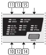
10 This LED array displays the sampling rate of the digital input signal. One LED lights up constantly when the sampling rate is kept accurately or does not deviate from the nominal value by more than approx. 2 kHz. Otherwise, the LED for the next value starts flashing.
⑪ The LOCK LED lights up when a valid digital signal—to which the ULTRAMATCH PRO can be synchronized—is applied to the active input. When digital input signals are being processed, this LED should be on all the time, showing the presence of a stable input signal.
The ERROR LED warns you of erroneous (or the absence of any) input signals. It displays various error modes, such as "Unlock," "Parity Error," "Bi-Phase Error" and "Confidence Error." The signal is then checked as to whether or not it is an audio signal. Any detected error makes the SRC2496 mute all of its outputs to protect down-stream audio equipment. As long as the ERROR LED is lit, the ULTRAMATCH PRO cannot process any input signals.
12 The EMPH LED shows you whether or not the input signal includes an emphasis marker. "Emphasis" is a high-frequency boost function that is applied during the digital recording but is undone during playback. When the LED lights up, the signal was emphasis-processed during recording. You should always make sure that the EMPH LEDs in the input and output sections read the same status.
The COPY LED (= copyright) lights up when the input signal was supplied from a copy-protected data carrier.
The ORIG LED (= original) informs you that the audio signal received is an original signal, i.e. that it can be copied (see chapter 2.1.3, section 28).
13 The AES/EBU LED lights up when an AES/EBU signal has been applied at the active input connector.
The same holds true for the S/PDIF LED, i.e. when a consumer-format signal has been applied.
If the unit is set to A/D and D/A converter mode, the S/PDIF LED lights up even when no digital signal is present. This is due to the circuitry used and does not indicate a malfunction of the unit. Further information on the formats AES/EBU and S/PDIF can be found in chapter 4.2.
14 Use the SOURCE switch to select the active input. Only one digital input can be activated at a time. However, in A/D-D/A converter mode, you can use one digital input and the analog inputs simultaneously (parallel A/D and D/A conversion). For further information please refer to chapter 3.1.3.
15 The LEDs XLR, RCA and OPTICAL indicate the input activated by the user.
2.1.2 Mode section
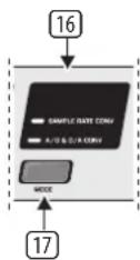
Fig. 2.4: Mode section
16 The two LEDs SAMPLE RATE CONV and A/D & D/A CONV inform you about the operating mode of your SRC2496, i.e. sampling rate converter or A/D-D/A converter.
17 Use the MODE switch to switch over between these two operating modes.
2.1.3 Output section
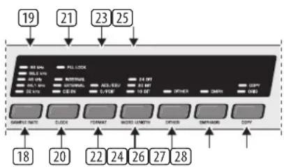
Fig. 2.5: Output section
EN
18 The SAMPLE RATE switch selects the sampling rate to which the input signal is to be converted or made available at the outputs. For this purpose, the SRC2496 must be set to internal mode, i.e. it has to function as a master unit (see sections 20 and 21).
The LEDs 32 kHz, 44.1 kHz, 48 kHz, 88.2 kHz and 96 kHz read the sampling rate selected with the SAMPLE RATE switch. If the sampling rate is preset by an external wordclock or generated via the digital input signal, the LEDs light up constantly, thus reading the external sampling rate (with a deviation of ±2 kHz). The next value (= deviation of >2 kHz) is displayed by one of the LEDs flashing.
20 The CLOCK switch allows you to select the source determining the sampling rate at the digital output of your ULTRAMATCH PRO.
21 The PLL LOCK LED shows you that your SRC2496 is processing properly the wordclock signals applied.
The INTERNAL LED lights up when the SRC2496 generates the sampling rate by itself (master), which is the preferred mode for the ULTRAMATCH PRO acting as an A/D converter.
The EXTERNAL LED lights up when the sampling rate is governed by an external wordclock signal. The external mode also allows you to generate sampling rates at the output that could not be generated by the SRC2496 as a master unit.
When the DIG IN LED lights up, your SRC2496 uses the wordclock signal included in the digital audio signal fed into the unit. This setting is useful if you do not want to convert the sampling rate, but only the format of the digital output signal (S/PDIF to AES/EBU or vice versa).
②2 The FORMAT switch determines the format of the digital data stream on the output side, as defined in the Channel Status data. Available formats are AES/EBU and S/PDIF.
23 The LEDs AES/EBU and S/PDIF show the adjusted output format, which is present at all three digital outputs. Using an appropriate cable (see chapter 5.3.5) you could also route an S/PDIF signal from the XLR output to a second unit, in case the RCA output is already in use.
24 Use the WORDLENGTH switch to select the digital word length of your choice (16, 20 or 24 bits).
If you want to set the digital word length to a lower value (e.g. to record 24-bit signals with 16 bits on CD, MD or DAT), we recommend that you switch on the dither function, so as to limit the distortion resulting from the omission of the additional bits to an inaudible minimum.
25 The LEDs 24 BIT, 20 BIT and 16 BIT read the word length selected.
26 The DITHER switch enables/disables the dither function. The corresponding LED lights up when this function is active. Here's a concise explanation of the dither function: Whenever analog signals are converted to digital (numerical values!), the finite number of digits available for the mathematical description of the analog signals (electrical voltages that are constant in the time and value domains) inevitably result in rounding errors and misinterpretations of the analog signals (quantization errors). In particular, signals with a very small amplitude are affected by an audible system error known as granular noise. Such errors can be suppressed by adding white noise. This type of noise has an exactly defined amplitude (minimum amplitude that can be detected only by measuring instruments and by no means affects the audio signal) and broadband frequency distribution, and is called dither signal. Combine this with the high internal resolution of 24 bits, and you can generate an audio signal of excellent quality.
Reducing the digital word length (e.g. from 24 bits to 20 bits) also means a reduction of the resolution. The resulting misinterpretations, which are more likely to result by this word length reduction can be purposefully suppressed with the dither function.
27 The EMPH LED lights up when the emphasis bit has been set in the output signal. Use the EMPHASIS switch to enable/ disable this function. To avoid sound deterioration, the LED in the output section should read the same status as the EMPH LED in the input section. In the rare case of a signal containing an emphasis bit without any treble boost applied, you can correct this here and switch off the emphasis bit (detailed information can be found in chapter 3.4).
28 The COPY switch (= copyright) allows you to set the status of the copy bits in the transmitted data stream. The LEDs COPY and ORIG inform you about the current status of the copy protection:
| digital recording only once | ||
| COPY-LED on | ||
| ORIG-LED on | ||
| digital recording not possible | ||
| COPY-LED on | ||
| ORIG-LED off | ||
| digital recording unlimited | ||
| COPY-LED off | ||
| ORIG-LED off | ||
| COPY-LED off | ||
| ORIG-LED on | ||
Tab. 2.1: Overview of copy bit settings
If both COPY and ORIG light up, you can make one copy only. Subsequently, the data will be copy protected. If only COPY lights up, digital copies cannot be made. If both LEDs are out, you can make digital recordings without any limitations. Press the switch to change the status of the determining bits and allow for unrestricted copying.
This option applies exclusively to S/PDIF signals, because the Serial Copy Management System (SCMS) exists in this format only. Signals based on the professional AES/EBU format can be copied freely.
Even though removing the copyright bit is possible, we would like to alert you about the fact that copyright and duplication rights must be safeguarded. We did not produce this equipment to facilitate illegal copying!
2.2 Rear panel of the ULTRAMATCH PRO
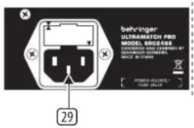
Fig. 2.6: Mains connector/fuse holder
29 MAINS CONNECTOR/FUSE HOLDER. Use the power cord supplied with the SRC2496 to connect the unit to the mains. Please note the instructions given in chapter 1.2. Blown fuses should only be replaced by fuses of the same type and rating.
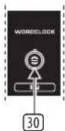
Fig. 2.7: Wordclock connector
30 The BNC connector WORDCLOCK is a high-impedance connector with no internal terminating impedance (75 Ohms). Use it to connect equipment for external synchronization of your ULTRAMATCH PRO. Please note the instructions given in chapter 3.2.3.
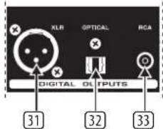
Fig. 2.8: Digital outputs
③1 The digital XLR output is the standard output connector for AES/EBU signals (AES/EBU LED lights up). When S/PDIF is selected, the XLR output also provides this signal. Further information on these connectors can be found in chapter 5.3.
32 This is the OPTICAL (Toslink) output connector of the ULTRAMATCH PRO. When the unit is shipped, the optical Toslink input/output connectors have dummy plugs attached to protect them from dirt and to prevent the emission of light. These dummy plugs can be removed easily if you wish to use the connectors. The digital standard format for this output is S/PDIF. However, you can also transmit AES/EBU signals via this output.
③3 RCA output. The digital standard format for this output is also S/PDIF. If AES/EBU has been selected in the output section, this output also provides AES/EBU signals. Unlike the XLR connector, however, this output allows for unbalanced signal transmission.
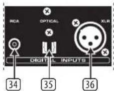
Fig. 2.9: Digital inputs
34—36 DIGITAL INPUTS.
34 The RCA input is the digital standard input for S/PDIF signals.
35 The OPTICAL input (Toslink) is also used for S/PDIF signals.
36 XLR input. The digital XLR input is the standard input connector for AES/EBU signals. It can also be used to feed in S/PDIF signals, like the RCA and OPTICAL inputs which can be used to process AES/EBU signals in addition to the S/PDIF format.
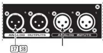
Fig. 2.10: Analog outputs and inputs
37 ANALOG OUTPUTS. These balanced analog XLR outputs (stereo) provide the analog signal generated by conversion from a digital format.
38 ANALOG INPUTS. Use these balanced analog XLR inputs (stereo) to feed in analog line level signals. Please note the instructions on level adjustment given in chapter 2.1.1 (section 4).
3. Applications
Your ULTRAMATCH PRO will soon prove to be a practical tool of valuable help in almost any situation. Its straightforward user interface is fun to work with. Don't be misled by the plain design: the SRC2496 is a really flexible tool in a variety of applications.
You don't need to own a professional recording studio to benefit from the wide range of features and functions implemented in the SRC2496. Problems with the interfacing of optical and coaxial connectors, removing copy protect bits, converting sampling rates from 48 to 44.1 or 32kHz —all of these tasks are quite common daily routines even in a home recording environment.
Additionally, the ULTRAMATCH PRO is the logical choice as a high-end A/D and D/A converter or enhanced source selector for digital inputs—whenever you need an inexpensive and reliable alternative to equipment with considerably higher prices.
3.1 A/D and D/A conversion with the ULTRAMATCH PRO
3.1.1 Converting analog to digital
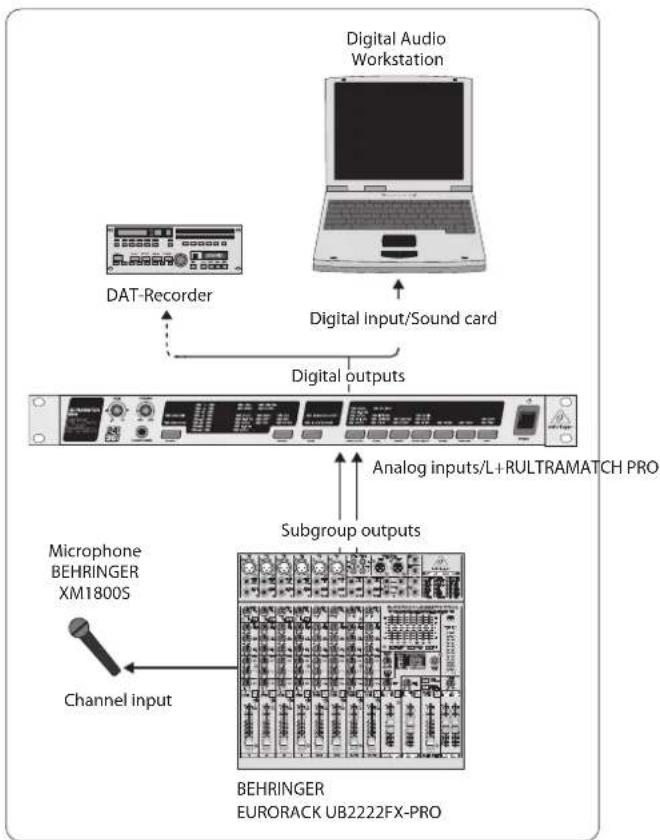
The ULTRAMATCH PRO is equipped with high-grade A/D and D/A converters. With the SRC2496 you own an excellent tool for preparing your analog audio data for digital processing or for converting analog signals directly and storing them on a digital medium. The analog input is set for studio levels (+4 dBu), but can be adapted to low-level signals with the GAIN control. Please use the level meter to adapt the level of the input signal, as described in chapter 2.1.1. The illustrations 3.1 and 3.2 below show you how to connect the unit.

flowchart
graph TD
    A["Digital Audio Workstation"] --> B["Digital input/Sound card"]
    B --> C["Digital outputs"]
    C --> D["Analog inputs/L+RULTRAMATCH PRO"]
    C --> E["Subgroup outputs"]
    E --> F["BEHRINGER EUORACK UB2222FX-PRO"]
    G["DAT-Recorder"] --> C
    H["Microphone BEHRINGER XM1800S"] --> E
    I["Channel input"] --> E
Fig. 3.1: Example: A/D conversion of a microphone signal
Fig. 3.1 shows a typical setup for recording a signal source on a digital recording device (here: hard-disk recording system). If your HD recording system is equipped with a digital interface, you can use the ULTRAMATCH PRO to "circumvent" the A/D converter on the sound card and thus avoid interference signals generated by the computer. By taking the signals from the subgroup outputs on your mixing console, you can record several signal sources at the same time by assigning (routing) them to the corresponding subgroups.
In practice, the ingenious design of the SRC2496 proves to be versatile to the point that you can also solve problems which are not directly related to a normal studio environment. For example, digital hi-fi recording equipment such as MD recorders (Mini Disc) have been met with widespread popularity in home systems. Unfortunately, however, such equipment cannot record with 32 kHz using their digital input.
Thus, it is impossible to record digital broadcasting programs directly to digital; D/A and A/D conversion steps are inevitable.
Not so with the ULTRAMATCH PRO, as it can convert the broadcast signal from 32 kHz to any other common sampling rate and also remove any form of copy protect information.
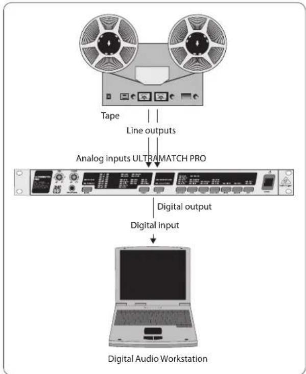
A second wiring setup shows how to copy tape recordings for restoring and subsequent archiving purposes on digital media.
flowchart
graph TD
    A["Tape"] --> B["Line outputs"]
    B --> C["Analog inputs ULTRAMATCH PRO"]
    C --> D["Digital output"]
    D --> E["Digital input"]
    E --> F["Digital Audio Workstation"]
Fig. 3.2: Example: A/D conversion of tape recordings
Since subgroup outputs on mixing consoles, as well as tape and line outputs on hi-fi amplifiers, usually provide unbalanced signals only, please note the corresponding instructions on how to connect the SRC2496 (chapter 5 "Installation").
3.1.2 Converting digital to analog
Using the ULTRAMATCH PRO as a digital-to-analog converter is interesting for all applications in which signals must be made audible again after digital processing, e.g. to "circumvent" D/A converters of inferior quality in equipment with a digital output (sound card).
This can be useful if your sound card is not shielded from electromagnetic interference generated by power supplies or graphics cards for example. You can feed the audio signal from the digital interface of the sound card to one of the digital inputs on the SRC2496 and then take it from the analog outputs. The type of cable required for connecting the sound card to the ULTRAMATCH PRO depends on the output connector used.
Detailed information on wiring setups can be found in chapter 5 "Installation".
3.1.3 Parallel A/D and D/A conversion
The SRC2496 offers you the possibility to simultaneously convert analog signals into digital, and vice versa. In A/D and D/A converter mode, you can only convert from digital to analog if the CLOCK switch in the output section has been set to DIG IN. In this case, the sampling rate will be determined by the digital signal applied. Otherwise, the ULTRAMATCH PRO can only be operated as an A/D converter, and the D/A converter function will be muted. In SRC mode the D/A converter is always active.
3.2 Sample rate conversion
No matter what type of digital audio signal you feed into the ULTRAMATCH PRO, it will convert it to a common standard format. Numerous conversion examples can be found in daily studio practice:
• Conversion of 48 kHz DAT recordings to the CD standard of 44.1 kHz
• Conversion of older digital recordings from 44.056 kHz to 32, 44.1, 48, 88.2 or 96 kHz
• Conversion of "foreign" material with 32 kHz to 44.1, 48, 88.2 or 96 kHz
- Conversion of audio data with a word length of 24 bits to 20 or 16 bits for recording on a digital medium
- Conversion of S/PDIF format to AES/EBU for easy manipulation of various parameters and improved (balanced) signal transmission
- Setting or removing copy protect bits for further processing of recordings in a studio environment
3.2.1 Typical studio application with DAT
Only recently has it become possible to use less expensive DAT recorders for direct recording from analog sources with a sampling rate of 44.1 kHz. Most consumer-level DAT recorders, however, record at 48 kHz. Usually, such recordings have to be transferred via an analog connection from DAT to a professional recorder. This process results in an unnecessary deterioration of the original quality of the material due to the additional D/A and A/D converters involved. With the ULTRAMATCH PRO you can eliminate this problem by converting the sampling rate purely in the digital domain, which allows for a considerably higher quality than you could achieve with analog converters.
Further problems, such as incorrect formats, significantly deviating or unstable sampling rates (as long as they do not deviate by more than ±12.5% from the current sampling rate), will also be corrected by the ULTRAMATCH PRO in real time, thus ensuring the successful transfer of your audio data.
3.2.2 Hard-disk recording
Hard-disk recording applications also require a uniform sampling rate, if possible the one used by the subsequent playback medium (CD). As it can convert audio material from 32, 48, 88.2 or 96 kHz to the standard 44.1 kHz, the ULTRAMATCH PRO makes sure that all sources can be used to feed audio material by way of a digital connection.
Of course, the ULTRAMATCH PRO can be inserted at any point in the audio processing path, i.e. also between the PC and the DAT recorder. Therefore, with uncritical audio material you can process the material at 32 kHz in the recording system (or higher, depending on which sampling rates can be processed by the HD recording system), and subsequently convert the completely edited material while transferring it to a DAT recorder at 44.1 kHz (or even at 48 kHz).
3.2.3 Master/slave problem solver
When a digital mixing console is used, it is at this point—if not earlier—that master/slave problems will be encountered. The explanation is simple: When using CD players, DAT recorder and HD recording systems in their “normal” applications, the responsibilities are clearly defined. The playback device is the master, the recording device is the slave, i.e. the CD player provides a clock rate of 44.1 kHz to which the DAT recorder is synchronized.
When using a mixing console, the CD player is the master, the console is the slave. However, this model collapses all of a sudden as soon as a DAT recorder is hooked up, which does not record but plays back too. The console can synchronize to one source only, the audio data from the other source would be processed incorrectly because the two devices are not in sync.
The need for synchronization in a digital studio is done justice connecting the equipment to one central sync source. For example, the console could be the master-supplying the remaining equipment with a reference signal (wordclock). However, this will only work if your other equipment has a sync input, i.e. can be used as a slave. In a studio with a digital tape machine, digital effects and hard-disk recording system it is impossible to connect commercially available CD players or DAT recorders to the mixing section of the console simply because they cannot be synchronized.
By inserting the BEHRINGER ULTRAMATCH PRO SRC2496 between the equipment to be synchronized and the mixing console input, the SRC2496 can deliver the audio signal with the studio clock rate entered via the external sync input (WORDCLOCK, 20 ). In this case, the ULTRAMATCH PRO works as intermediate gear of sorts, whose toothed transmission always ensures that there is an appropriate gap in the gearwheel. It synchronizes the signal coming from the devices to be synchronized, while converting to the desired sampling rate in compliance with the wordclock signal.
In a studio with a central clock generator, it is therefore possible to use the ULTRAMATCH PRO to connect any unit to any other, regardless of any other options available.
Even if the central clock does not correspond exactly to one of the sampling rates, the ULTRAMATCH PRO will assign a corresponding marker to the output signal! This marker depends on the automatically detected and displayed sampling rate, which is important because DAT recorders usually “refuse” to enter record mode if an incorrect sampling rate has been indicated.
3.2.4 Bridging unformatted passages
DAT recorders, in particular, produce tiny format gaps between individual recorded passages on the tape when intermittent recordings are made. Also, when you transfer older recordings it can happen that short passages with a different sampling rate than that of the current recording remain stored on tape. In such cases, the ULTRAMATCH PRO converts this host of single pieces of information into a continuous data stream with a fixed sampling rate. Even if the DAT recorder or any other digital source is stopped or switched off, the ULTRAMATCH PRO will continue to generate a continuous signal (depending on the digital signal, if synchronized to it).
3.3 Removing copy protect information
The original copy protect mechanism used in DAT recorders was simple but effective: It was impossible to make digital recordings from a CD. Later, a step-by-step mechanism was introduced with SCMS, which allowed at least for one digital copy from CD. The routine implemented in SCMS depends on the generation ( x^th copy) and the origin (category) of the digital audio material. In professional studio engineering a copy protect mechanism does not make any sense, which is why there is none defined in the AES/EBU standard.
Since many studios use inexpensive consumer devices for cost reasons, copy protect and/or format incompatibility problems (professional/consumer) are encountered frequently. The SRC2496 can ignore all types of copy protect information and generate a new, completely free marker that allows for multiple copying. Thus, you can use your ULTRAMATCH PRO to copy material from one consumer DAT to another. Further information on this subject can be found in chapter 2.1.3, section 28.
3.4 Noise reduction with emphasis
A very special feature is the option to influence the set emphasis bit.
"Emphasis" here means a noise reduction process with a treble boost step involved prior to recording. This treble boost is undone during playback. A specific bit (emphasis bit) in the digital data stream contains the information whether or not the signal has been processed with this technique. It is however NOT a modification of the audio signal, but only of the emphasis marker contained in the digital data stream.
EN
So much for the theory. In practice, a lit EMPHASIS LED does not necessarily show that the emphasis function has really been applied. In several situations the emphasis bit was set during the mastering and editing process due to defective hardware/software—without any treble boost applied. This error usually remains undetected when the material is transferred, because modern DAT recorders no longer have an emphasis indicator for reasons of rationalization. When the master tape—usually only monitored briefly on the DAT recorder due to lack of time—arrives at the customer's end, it gives him a big surprise: The treble range has been cut in the DAT recorder by more than 10 dB, which cannot be undone and results in a dull sound that lacks brilliance in the treble range. It is for this reason that we equipped the ULTRAMATCH PRO both with an emphasis status LED and with an additional switch for manual correction of the emphasis bit setting.
3.5 Line booster, signal refresher
Longer cable lengths or the use of a digital patchbay lead to deterioration of signal quality, which may result in a higher noise floor or even connection failures. Using special input circuitry your ULTRAMATCH PRO removes jitter, interference and level loss, thus restoring the signal to perfect quality. As a consequence, you can also use the SRC2496 to refresh the signal over longer cable lengths or to restore attenuated and distorted signals.
3.6 Correcting incorrect sample rates
The sample rate of any equipment is subject to fluctuation due to temperature and ageing effects. Normally, an automatic locking circuit ensures reliable operation even with varying or slightly fluctuating clock signals. If such fluctuations exceed a certain level, however, the receiving equipment cannot be synchronized any longer to the clock rate supplied and therefore fails to function properly.
Your ULTRAMATCH PRO is totally free from such restrictions, as it works over the entire bandwidth from 31 to 100 kHz, rather than only within a small range around the actual sampling rate. The signal output by the SRC2496 is always synchronized correctly to the value selected. Thus, you can use your ULTRAMATCH PRO to "rescue" and work with sampling rates that have been modified deliberately (vari-pitch function on sampling keyboards or CD players) or fail to fall within the adjusted range due to rate fluctuations.
3.7 Vari-speed application
There are several reasons for modifying the speed of a digital playback, e.g. to change the pitch or synchronize the playback to other equipment. In such cases, the ULTRAMATCH PRO can track the sampling rate as it changes and then output the signal with a fixed rate of 44.1 kHz (or any other selectable or wordclock-defined value). Thus, it reliably removes sampling rate fluctuations, which could otherwise make it impossible to process the digital audio material any further in the digital domain.
At its digital input, the ULTRAMATCH PRO accepts sampling rate fluctuations of up to ±12% from the adjusted sampling rate, without producing any distortion at its output. When things get worse, the connection will not be interrupted, but temporary drops in the signal quality (distortion) may occur.
3.8 Format converter
Digital data transfer is frequently affected by problems with the format required. While some devices specifically need S/PDIF signals on the input side, others can only output AES/EBU. With the SRC2496 this problem is now history. The input of your ULTRAMATCH PRO readily accepts any standard used today. On the output side, you can select either AES/EBU or S/PDIF, so that it is just a matter of one key press to realize the successful transfer of your audio material.
3.9 Format interface
Many CD players have no coaxial but only an optical output. Some DAT recorders, on the other hand, only have a coaxial input. Digital interface cards for personal computers are usually equipped either with optical or coaxial connectors. So, when you try to transfer data from one unit to another you are likely to encounter incompatibility problems, in that one unit has an optical connector, while the other has a coaxial RCA connector. Connection to professional equipment is difficult because of the XLR connectors used there, or even impossible if it features optical interfaces.
Such incompatibilities between inputs and outputs are definitely a thing of the past with the ULTRAMATCH PRO. For example, if the CD player only has an optical digital output, while the DAT recorder is equipped with a coaxial RCA input, your SRC2496 will easily eliminate the resulting connection problems with its three inputs and outputs in all formats. Your ULTRAMATCH PRO allows for interconnecting virtually all equipment that is available on the market today!
3.10 Patchbay/splitter
The digital outputs of your ULTRAMATCH PRO can all be operated at the same time. In this case, the input selector functions as a kind of miniature patchbay determining which signal is sent to the output. It is not necessary to switch-over the output, because you can freely select on the down-stream devices which signal to accept (example: recording active/inactive). Therefore, the outputs of the ULTRAMATCH PRO carry the identical signal all the time and are operative simultaneously.
The parallel operation of all three outputs enables you to use your SRC2496 as a splitter, which is useful for copying material to several DAT recorders. With some special types of equipment in particular that does not allow for looping through the digital data from the input to the output, this useful function makes it possible to split up the signal.
4. Technical Background
4.1 A short digression into digital sample rate conversion
In the past, the conversion of various sample rates into a fixed value necessitated a whole rack full of components and even then had some disadvantages that could be measured as increased noise, distortion or undesirable mirror frequencies (high-frequency chirping). On the other hand, the sampling rate converter chip installed in the ULTRAMATCH PRO converts in real time and with 24-bit precision. Its processing is absolutely inaudible and can only be identified with state-of-the-art, extremely expensive measuring instruments.
The functional principle is difficult to comprehend, even for professionals. That is why we are presenting you with an equivalent model, which describes the processes taking place in the processor in an easily understandable manner. The processor carries out an oversampling at the input signal. Between each sample, more samples are inserted, thereby significantly increasing the number of sampling points by filling in the gaps. Subsequently, the signal passes through a variable low-pass filter, which ensures that the correct limit, below which no problems with mirror frequencies (aliasing) occur, is observed. Then, the number of sampling points is distributed in such a way as to obtain the desired sampling rate at the output. This enormous oversampling allows the SRC processor to achieve excellent precision in the complete conversion range. Moreover, it also simultaneously eliminates any jitter present in the input signal.
There is no doubt that digital signal processing guarantees the lowest distortion and noise values. However, up until now signal conversion, specifically sampling rate conversion, had partially led to considerable distortion and interference: If you tried to use traditional methods, the incoming data quantity would far exceed any hardware capacity. If data was put into smaller pieces to avoid storage problems, the necessary turnaround time would prevent any practical
application. Therefore, programmers continue to experiment with the most varied of algorithms, ending up, however, always having to make a compromise between computation efforts and sound quality.
By processing data in real time, the processor used in the BEHRINGER ULTRAMATCH PRO can process incredible amounts of data.
The noise and interference floor is thus below -117 dBFS, and the distortion values, even with difficult input signals, are below -104 dBFS. The ULTRAMATCH PRO remains practically inaudible as such values are not normally achieved either by the A/D or the D/A converter, and certainly not by the CD as the final product.
4.2 AES/EBU and S/PDIF standards
In principle there are two standards, the most important electrical characteristics of which can be seen in tab. 4.1.
AES/EBU is the professional, balanced connection via XLR connectors. This interface is based on two identical protocols published in November 1985 (EBU Tech. 3250-E) by the European Broadcast Union and in December 1985 by the Audio Engineering Society (AES3-1985). Sony and Philips oriented themselves to this standard and developed a further interface with unbalanced signal routing and a few other major differences, predominantly related to the assignment of the channel status bits. This interface, named after the two companies and known as S/PDIF (Sony/Philips Digital Interface), uses either RCA connectors or optical connections with optical fiber cables. The procedure, standardized in IEC 958, made a name for itself mainly due to efforts to introduce a copy protect technique. This standard also describes the revised AES/EBU interface, which was adapted to the S/PDIF format and named IEC 958 Type I (professional). The name of the S/PDIF interface is then IEC 958 Type II (consumer). Your ULTRAMATCH PRO uses the latest versions of each of the standards, AES/EBU (AES3), IEC 60958 and EIAJ CP-1201 (Japanese standard).
| Type AES/EBU IEC 958 Type II (S/PDIF) | |
| Connection XLR RCA/optical | |
| Mode Balanced Unbalanced | |
| Impedance 110 Ohms 75 Ohms | |
| Level 0,2 V to 5 Vpp 0,2 V to 0,5 V pp | |
| Clock accuracy Not specified | I: ± 50 ppm II: 0,1%III: Variable pitch |
| Jitter ± 20 ns Not specified | |
Tab. 4.1: Important data for AES and IEC 958 Type II specifications
Table 4.2 illustrates part of the structure of the professional format, as it would normally be used with AES/EBU connections.
| Byte Bit | ||||||||
| 0 | 1 | 2 | 3 | 4 | 5 | 6 | 7 | |
| 0 | P/C | Audio | Emphasis | Locked | Sampl. freq. | |||
| 1 | Channel mode | Use of user bits | ||||||
| 2 | Use of AUX bits | Sample length | Reserved | |||||
| 3 | Reserved for description of multichannel recording | |||||||
| 4 | Audio ref. | Reserved | ||||||
| 5 | Reserved | |||||||
Tab. 4.2: Markers in professional format (AES/EBU)
Table 4.3 presents the corresponding consumer-format data, as normally used with S/PDIF-connections.
| Byte | Bit | |||||||
| 0 | 1 | 2 | 3 | 4 | 5 | 6 | 7 | |
| 0 | P/C | Audio | Copy | Emphasis | Mode | |||
| 1 | Category code | Gen. st. | ||||||
| 2 | Source number | Channel number | ||||||
| 3 | Sampling frequency | Clock acc. | Reserved | |||||
Tab. 4.3: Markers in consumer format IEC 958 Type II (S/PDIF)
The first bit already defines whether the following bits are to be understood as professional or consumer-format bits. As shown, the audio information can be found at the same position in the data stream, in principle making both formats compatible. There are, however, information blocks that differ in both norms. If a piece of equipment, such as a commercially available DAT recorder, has only one S/PDIF input, the equipment will usually understand that format only. It will thus usually stop when supplied with professional-format data. The reason is simple: as shown in the illustrations, processing a professionally-coded signal with equipment that can only understand consumer format can lead to malfunctions relating to the copy protect bit and the emphasis!
However, this point is not always readily evident, as is the case with plug-and-socket connectors (e.g. 1/4" TRS connectors, mini-jacks and special adapters for Sub-D instead of XLR connectors). A lot of equipment has no stop function while other equipment can understand both formats despite having only one type of connector.
In all of these cases using the ULTRAMATCH PRO as the ultimate problem solver will soon pay off. Virtually, all common digital signals it receives at the input appear at the output with new, clean markers in the respective chosen format.
5. Installation
5.1 General connection notes
The ULTRAMATCH PRO's digital input and output connections are short-circuit-proof and transformer-balanced. This rules out any possibility of ground loops caused by additional ground connections, even when using the RCA connectors. Furthermore, the completely potential-free concept of the digital connectors allows for using adapters in order to, e.g. route the RCA connector signal to the XLR input of another piece of equipment.
Unlike digital connectors, analog connectors are not galvanically separated, but have a balanced design and are thus unproblematic in regard to ground loops.
5.2 Analog inputs and outputs
In order to give your audio signals the best possible protection from electromagnetic interference, the ULTRAMATCH PRO has balanced XLR inputs and outputs. As previously described, the level at the analog inputs can be adjusted with the GAIN control. The outputs operate at studio level (+4 dBu). Please see the following illustrations for the pin assignment of the connectors.
Of course, it is also possible to send signals to the SRC2496 from unbalanced outputs (e.g. sound cards or mixing console outputs) in order to further process them in digitized form. Receiving analog signals (e.g. when using a high-end D/A converter between a CD-Player and amplifier) from the ULTRAMATCH PRO via unbalanced connectors (e.g. hi-fi amplifier or tape recorder) is not a problem, too.

When using the XLR connectors in an unbalanced configuration, pins 1 and 3 on the connectors inserted must be interconnected!
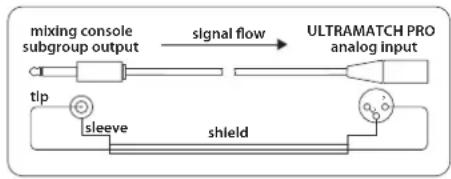
flowchart
graph LR
    A["mixing console subgroup output"] -->|signal flow| B["ULTRAMATCH PRO analog input"]
    C["tip"] --> D["sleeve"]
    D --> E["shield"]
Fig. 5.1: Unbalanced transmission to the ULTRAMATCH PRO
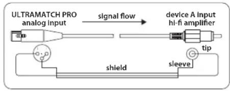
flowchart
graph LR
    A["ULTRAMATCH PRO analog input"] -->|signal flow| B["device A Input hi-fi amplifier"]
    B --> C["shield"]
    C --> D["sleeve"]
    D --> E["slip"]
    E --> F["tip"]
Fig. 5.2: Unbalanced transmission from the ULTRAMATCH PRO
5.3 Digital inputs and outputs
5.3.1 Balanced XLR connection
The digital XLR inputs and outputs are not bound by the AES/EBU protocol. They accept and deliver data streams in both the professional and the consumer format. Should the RCA input already be occupied by another device, it is even possible to connect the RCA output of, say, a CD player to the ULTRAMATCH PRO XLR input by using an adapter. To do this, you will need a cable such as the one shown in fig. 5.2, except that instead of a female XLR connector, a plug must be mounted.
The following figure illustrates how to correctly connect the balanced input and output connectors. Basically, it is the same wiring scheme normally used for balanced audio connections such as, for example, the connection between a microphone and a mixing console.
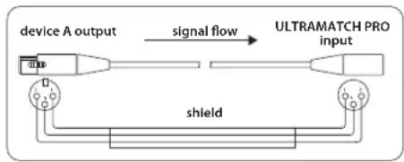
flowchart
graph LR
    A["device A output"] -->|signal flow| B["ULTRAMATCH PRO input"]
    B --> C["shield"]
    C --> D["Output"]
    style A fill:#f9f,stroke:#333
    style B fill:#ccf,stroke:#333
    style C fill:#cfc,stroke:#333
    style D fill:#fcc,stroke:#333
Fig. 5.3: Connecting the ULTRAMATCH PRO in a balanced configuration
Selecting the correct cable is not critical. For distances of less than 20 m, generally available microphone cables have no negative effect. For greater distances or higher requirements (mobile operation, powerful high-frequency fields), however, you should use special 110-Ohm cable with double shielding.
5.3.2 Unbalanced coaxial RCA connection
The RCA inputs and outputs, in turn, are not bound to the S/PDIF format. They accept and deliver data streams in both the professional and the consumer format. It is even possible to connect the XLR output (e.g. from the BEHRINGER ULTRA-CURVE PRO DSP8024 or other equipment) to the RCA input on the ULTRAMATCH PRO by using an adapter. Whether or not the reverse will work, namely connecting the ULTRAMATCH PRO's RCA connector to the XLR input of another unit, depends on the sensitivity of the XLR input in question.
The following figure illustrates the correct connection for unbalanced input and output connections via RCA plugs.
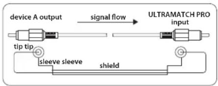
flowchart
graph LR
    A["device A output"] -->|signal flow| B["ULTRAMATCH PRO input"]
    C["sleeve sleeve"] --> D["shield"]
    E["tip tip"] --> A
Fig. 5.4: Connecting the ULTRAMATCH PRO in an unbalanced configuration
Basically, it is the same wiring scheme as is the norm for unbalanced audio connections in hi-fi systems, e.g. between a CD player and amplifier.
For distances less than 10 m, standard coaxial line cable has no negative influence. However, should greater distances be involved, you should use XLR.
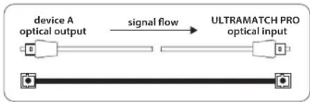
5.3.3 Optical connection
Toslink optical inputs and outputs are also not bound by the S/PDIF format. They accept and deliver data streams in both the professional and the consumer format. Optical connections are by nature not sensitive to electric interference fields, easy to cable and astonishingly robust.
The following figure illustrates how to correctly connect the optical input and output connections.
flowchart
graph LR
    A["device A\noptical output"] -->|signal flow| B["ULTRAMATCH PRO\noptical input"]
Fig. 5.5: Connecting the ULTRAMATCH PRO optically via Toslink
For many consumer devices the consumer format at the optical input is an absolute necessity, otherwise they do not accept the signal.
The ULTRAMATCH PRO does not support the ADAT multi-track format, which can thus neither be looped through nor converted. (ADAT is a registered trademark of the Alesis Corporation)
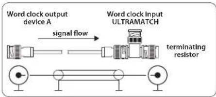
5.3.4 Wordclock
Feeding a wordclock signal into the rear BNC connector enables external synchronization of the ULTRAMATCH PRO. Wordclock signals are normally distributed in a network configuration, i.e. are relayed and terminated with 75-Ohm coaxial cable, BNC-T adapters and terminating resistors. Commercially available BNC cables are usually used as connecting cables. In order to offer maximum flexibility, the ULTRAMATCH PRO's BNC input has a high-impedance design and is not equipped with an internal 75-Ohm terminating resistor. Should the ULTRAMATCH PRO be the last device in the signal chain, however, it is necessary to put a T-connector into the BNC connector. A 75-Ohm terminating resistor (in the form of a short BNC plug) goes on one end of the T-connector and the BNC cable from the "master" delivering the wordclock signal on the other end.
The following figure shows how to correctly connect the unbalanced wordclock input. The wiring scheme is the same as is used for networking in computer technology and you can thus obtain the appropriate accessories (commercially available cable, T-connectors, terminating resistors) in specialist computer shops.
flowchart
graph LR
    A["Word clock output device A"] -->|signal flow| B["Word clock Input ULTRAMATCH"]
    B --> C["terminating resistor"]
Fig. 5.6: Unbalanced connection (termination) of the wordclock input to the ULTRAMATCH PRO
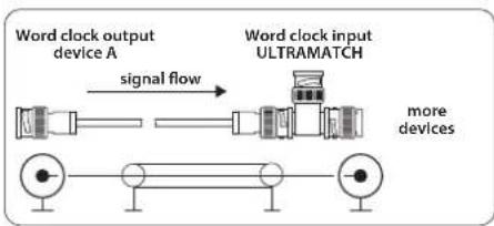
When the ULTRAMATCH PRO is used as part of a chain of wordclock devices, it is also supplied with a wordclock signal via a T-connector, which is then relayed to the next device from the other side of the T-connector via an additional BNC cable. The last device in the chain is then, as previously described, locked by way of the T-connector and a 75-Ohm resistor. Some devices also have a switchable terminating resistor, in which case the T-connector and terminating resistor are not necessary.
flowchart
graph LR
    A["Word clock output device A"] -->|signal flow| B["Word clock input ULTRAMATCH"]
    B --> C["more devices"]
Fig. 5.7: Unbalanced connection (loop through) of the wordclock input
5.3.5 Connecting with an adapter
In certain cases it makes sense to connect the SRC2496's inputs and outputs to other devices via a cable adapter. If, for example, you wish to simultaneously connect two DAT recorders and each has only one RCA (S/PDIF) connector, you can easily connect one of the DAT recorders to the ULTRAMATCH PRO using an XLR/RCA adapter. The correct connection assignment of the adapter cable for this purpose can be found in fig. 5.2.
5.4 Headphones output
The headphones output on the front panel of the SRC2496 is on a 14 " TRS connector. The connection assignment of the corresponding plug is shown in fig. 5.8.
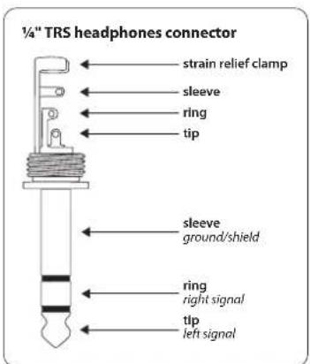
Fig. 5.8: Correct wiring assignment for headphones connection
Please note that high volume levels can damage your hearing and/or your headphones. Turn the PHONES control to the far left before turning on the device. Always take care to keep the volume level at an appropriate level.
6. Specifications
Synchronization
Internal sampling rates 32, 44.1, 48, 88.2, 96 kHz
Synchronization via digital input accepts all sampling rates and wordclock between 31 and 100 kHz, automatic synchronization by PLL
Digital Input 1
Type XLR, transformer-balanced
Input impedance 110 ohms
Nominal input level 0.2 V to 5 V, peak-to-peak
Digital Input 2
Type RCA, transformer-balanced
Input impedance 75 ohms
Nominal input level 0.2 V to 5 V, peak-to-peak
Digital Input 3
Type Toslink, optical fiber cable
Synchronization Input
| Type | BNC |
| Input impedance 50 kohms | |
| Standard Wordclock (1 x FS) | |
| Nominal input level 2 V to 6 V peak-to-peak | |
Digital Output 1
| Type XLR, transformer-balanced | |
| Output impedance 110 ohms balanced | |
| Nominal output level | 3.5 V peak-to-peak |
Digital Output 2
| Type RCA, transformer-balanced | |
| Output impedance 75 ohms | |
| Nominal output level | 0.5 V, peak-to-peak |
Digital Output 3
Type Toslink, optical fibre cable
EN
Analog Inputs
Type XLR, balanced
Input impedance 20 kohms
Converter 24-bit/96 kHz 128/64 times
oversampling delta-sigma
AKM A/D converter
Input level -4 dBu to +22 dBu for 0 dBFS, adjustable
S/N-Ratio >105 dB
Analog Outputs
Type XLR, balanced
Output impedance 160 ohms
Converter 24 bit/96 kHz 128 times oversampling
delta-sigma AKM D/A converter
Output level +16 dBu @ 0 dBFS
S/N Ratio >108 dB
Jitter Suppression
Jitter permitted at input >40 ns
Internal jitter at input <2 ns
Internal jitter with external <20 ns, 10 ns typ. Synchronization
Channel Status Information in Output Signal
| Professional mode | Professional, audio use, stereo, no emphasis or 50/15 μs, Fs = 32, 44.1, 48, 88.2, 96 kHz |
| Consumer mode | Consumer, audio use, 2-channel, original material switchable, copy permit switchable, no emphasis or 50/15 μs, Fs = 32, 44.1, 48 kHz; (88.2, 96 kHz not defined) |
Power Supply
Mains Voltage
U.S.A./Canada 120 V\~, 60 Hz
| Europe/U.K./Australia | 230 V~, 50 Hz |
| Japan | 100 V~, 50 - 60 Hz |
General export model 120/230 V\~, 50 - 60 Hz
| Power consumption | 15 W |
| Fuse | 100 - 120 V~: T 250 mA H 250 V200 - 240 V~: T 125 mA H 250 V |
| Mains connection | Standard IEC receptacle |
Dimensions/Weight
| Dimensions | approx. 1.75 x 19 x 8.54" approx. 44.5 x 483 x 217 mm |
| Weight | approx. 5.06 lbs/2.3 kg |
| Shipping weight | approx. 7.48 lbs/3.4 kg |
BEHRINGER is constantly striving to maintain the highest professional standards. As a result of these efforts, modifications may be made from time to time to existing products without prior notice. Specifications and appearance may differ from those listed or illustrated.
FEDERAL COMMUNICATIONS COMMISSION COMPLIANCE INFORMATION

BEHRINGER
ULTRAMATCH PRO SRC2496
Responsible Party Name: MUSIC Group Services US Inc.
Address: 18912 North Creek Parkway,
Suite 200 Bothell, WA 98011, USA
Phone/Fax No.: Phone: +1 425 672 0816
Fax: +1 425 673 7647
ULTRAMATCH PRO SRC2496
complies with the FCC rules as mentioned in the following paragraph:
This equipment has been tested and found to comply with the limits for a Class B digital device, pursuant to part 15 of the FCC Rules. These limits are designed to provide reasonable protection against harmful interference in a residential installation. This equipment generates, uses and can radiate radio frequency energy and, if not installed and used in accordance with the instructions, may cause harmful interference to radio communications. However, there is no guarantee that interference will not occur in a particular installation. If this equipment does cause harmful interference to radio or television reception, which can be determined by turning the equipment off and on, the user is encouraged to try to correct the interference by one or more of the following measures:
• Reorient or relocate the receiving antenna.
- Increase the separation between the equipment and receiver.
- Connect the equipment into an outlet on a circuit different from that to which the receiver is connected.
- Consult the dealer or an experienced radio/TV technician for help.
This device complies with Part 15 of the FCC rules. Operation is subject to the following two conditions:
(1) this device may not cause harmful interference, and
(2) this device must accept any interference received, including interference that may cause undesired operation.
Important information:
Changes or modifications to the equipment not expressly approved by MUSIC Group can void the user's authority to use the equipment.

natural_image
Black-and-white photo of a smiling woman making a hand gesture with both hands (no text or symbols visible)We Hear You