
HTR-4065 - Receiver YAMAHA - Free user manual and instructions
Find the device manual for free HTR-4065 YAMAHA in PDF.


| Product type | Audio/Video receiver |
| Brand | Yamaha |
| Model | HTR-4065 |
| Dimensions (W x H x D) | 435 x 171 x 375 mm |
| Weight | 10,1 kg |
| Power supply | 220-240 V, 50/60 Hz |
| Power consumption | 490 W |
| Output power | 7 channels × 100 W (6 ohms, 1 kHz, 0,9% THD) |
| Supported audio formats | Dolby TrueHD, DTS-HD Master Audio, PCM |
| HDMI inputs | 4 inputs, 1 output (ARC) |
| Digital audio inputs | 1 coaxial, 2 optical |
| Analog audio inputs | 6 stereo RCA |
| Pre-amplified outputs | 1 subwoofer |
| FM/AM radio | Yes, 40 presets |
| Network functions | None |
| Remote control | Included |
| Cleaning | Dry, soft cloth, no chemicals |
| Safety | Unplug before cleaning, avoid moisture |
| Spare parts and repairability | Available from Yamaha after-sales service |
Frequently Asked Questions - HTR-4065 YAMAHA
User questions about HTR-4065 YAMAHA
0 question about this device. Answer the ones you know or ask your own.
Ask a new question about this device
Download the instructions for your Receiver in PDF format for free! Find your manual HTR-4065 - YAMAHA and take your electronic device back in hand. On this page are published all the documents necessary for the use of your device. HTR-4065 by YAMAHA.
USER MANUAL HTR-4065 YAMAHA
This document explains how to set up a 5.1- or 7.1-channel system
(HTR-5065 only) and play back surround sound from a BD/DVD on the unit.

To reduce the impact on natural resources, the Owner's Manual for this product is supplied on CD-ROM. For more information about this product, refer to the Owner's Manual on the supplied CD-ROM.

PDF versions of this guide and "Owner's Manual" can be downloaded from the following website. http://download.yamaha.com/
1 Preparation
Accessories
Check that the following accessories are supplied with the product.
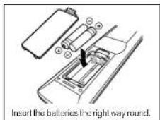
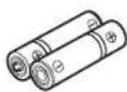
□ Remote control □ Batteries

(AAA, R03, UM-4) (x2)

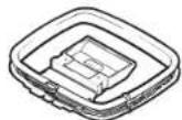
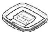
□ AM antenna

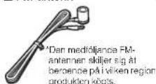
□FM antenna

□ YPAO microphone

□ CD-ROM
(Owner's Manual)

□ Safety Brochure □
Easy Setup Guide

- The illustrations of the main unit and remote control used in this guide are of the HTR-5065 (U.S.A. model), unless otherwise specified.
Cables required for connections
The following cables (not supplied) are required to build the system described in this document.
- Speaker cables (depending on the number of speakers)
• HDMI cable (x2)
• Audio pin cable (x1) - Digital optical cable (x1) (not required if your TV supports ARC [Audio Return Channel])
2 Placing speakers
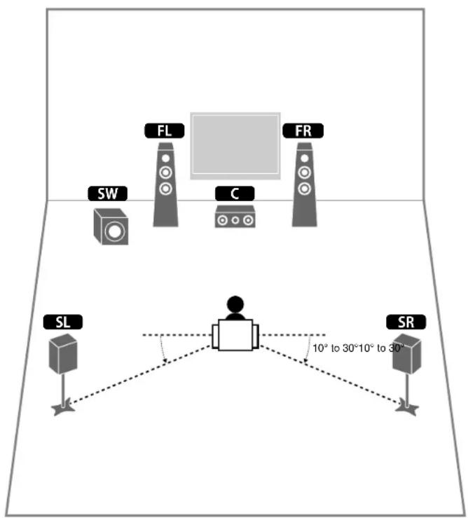
Set up the speakers in the room using the following diagram as a reference.
For information on other speaker systems, refer to "Owner's Manual".
5.1-channel system
7.1-channel system (HTR-5065 only)
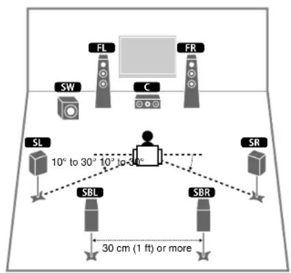
FL Front speaker (L)
FR Front speaker (R)
C Center speaker
SL Surround speaker (L)
SR Surround speaker (R)
SBL Surround back speaker (L)
SBR Surround back speaker (R)
SW Subwoofer
3 Connecting speakers/subwoofer
• (U.S.A. model only)
Under its default settings, the unit is configured for 8-ohm speakers. When connecting 6-ohm speakers, set the unit's speaker impedance to "6 Ω MIN". For details, see "Setting the speaker impedance" in "Owner's Manual".
• (Except for U.S.A. model)
Use speakers with an impedance of at least 6 Ω.
- Use a subwoofer equipped with built-in amplifier.
- Before connecting the speakers, remove the unit's power cable from the AC wall outlet and turn off the subwoofer.
- Ensure that the core wires of the speaker cable do not touch each other or come into contact with the unit's metal areas. This may damage the unit or the speakers. If the speaker cables short circuit, "Check SP Wires" will appear on the front display when the unit is turned on.
■Connecting speaker cables
Speaker cables have two wires. One is for connecting the negative (-) terminals of the unit and the speaker, and the other is for the positive (+) terminals. If the wires are colored to prevent confusion, connect the black wire to the negative and the other wire to the positive terminals.
①Remove approximately 10 mm (3/8") of insulation from the ends of the speaker cable and twist the bare wires of the cable firmly together.
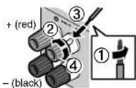
②Loosen the speaker terminal.
③Insert the bare wires of the cable into the gap on the side (upper right or bottom left) of the terminal.
④Tighten the terminal.
Using a banana plug
(U.S.A. and China models only)
①Tighten the speaker terminal.
②Insert a banana plug into the end of the terminal.

1 Connect the front speakers (FL/FR) to the FRONT (L/®) terminals.

flowchart
graph TD
    A["The unit (rear)"] --> B["Controller 1"]
    A --> C["Controller 2"]
    A --> D["Controller 3"]
    A --> E["Controller 4"]
    A --> F["Controller 5"]
    B --> G["FL"]
    C --> H["FR"]
    D --> I["C"]
    E --> J["SL"]
    F --> K["SR"]
2 Connect the center speaker (C) to the CENTER terminal.

flowchart
graph TD
    A["The unit (rear)"] --> B["Control Unit"]
    B --> C["FL"]
    B --> D["FR"]
    B --> E["SW"]
    B --> F["SL"]
    B --> G["SR"]
    C --> H["Central Monitor"]
    D --> H
    E --> H
    F --> H
    G --> H
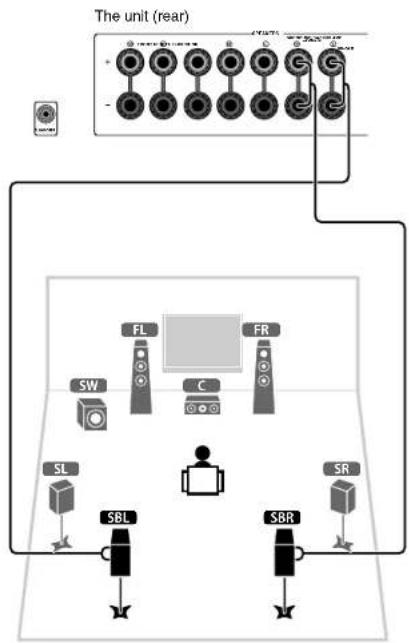
3 Connect the surround speakers (SL/SR) to the SURROUND (L/R) terminals.
4 Connect the subwoofer (SW) to the SUBWOOFER jack.
For 7.1-channel system (HTR-5065 only)
Connect the surround back speakers (SBL / SBR) to the SURROUND BACK (L/R) terminals.

flowchart
graph TD
    A["The unit (rear)"] --> B["SW"]
    A --> C["FL"]
    A --> D["C"]
    A --> E["FR"]
    A --> F["SL"]
    A --> G["SR"]
    B --> H["Camera"]
    C --> I["Camera"]
    D --> J["Camera"]
    E --> K["Camera"]
    F --> L["Camera"]
    G --> M["Camera"]

flowchart
graph TD
    A["The unit (rear)"] --> B["Switch"]
    B --> C["SW"]
    B --> D["FL"]
    B --> E["FR"]
    C --> F["SL"]
    D --> G["SBL"]
    E --> H["SBR"]
    F --> I["Central Monitor"]
    G --> I
    H --> I
    I --> J["Output"]
4 Connecting external devices

1 Connect external devices to the unit.
①Connect a BD/DVD player to the unit with an HDMI cable.
If the BD/DVD player is currently connected to the TV directly with an HDMI cable, disconnect the cable from the TV and connect it to this unit.
②Connect a TV to the unit with the other HDMI cable.
③Connect a TV to the unit with a digital optical cable. This connection is required to play back TV audio on the unit. This connection is not required if your TV supports ARC (Audio Return Channel).
④Connect the power cable to an AC wall outlet.

- For information on how to connect radio antennas or other external devices, see "PREPARATIONS" in "Owner's Manual".
2 Turn on the unit, the TV and the BD/DVD player.
3 Use the TV remote control to change the TV input to video from the unit.
The connections are complete. Proceed to the next page to optimize the speaker settings.

- By connecting a TV to the unit with an HDMI cable, you can configure the unit's settings with the menu displayed on the TV. In addition, you can select the on-screen menu language from English (default), French, German, Spanish, Russian and Chinese. For details, refer to "Owner's Manual". In this guide, illustrations of English menu screens are used as examples.
5 Optimizing the speaker settings automatically (YPAO)
The Yamaha Parametric room Acoustic Optimizer (YPAO) function detects speaker connections, measures the distances from them to your listening position(s), and then automatically optimizes the speaker settings, such as volume balance and acoustic parameters, to suit your room.
- During the measuring process, test tones are output at high volume. Ensure that the test tones do not frighten small children. Also, refrain from using this function at night when it may be a nuisance to others.
- During the measuring process, you cannot adjust the volume.
- During the measuring process, keep the room as quiet as possible.
- Do not connect headphones.
- Do not stand between the speakers and the YPAO microphone during the measurement process (about 3 minutes).
- Move to the corner of the room or leave the room.
Preparing for YPAO

1 Connect the YPAO microphone to the YPAO MIC jack on the front panel.
The following screen appears.
![Auto Setup Start Exit Press SETUP key to Start Power Amp Assign Basic YPAD +[SETUP]:Start VOL-408](/content/2026/06/1276756/images/22e4f4f314ce6476ffa7755a4e908f6f95b0a8a65e87b5883a13c5bbffc1637e.jpg)

- To cancel the operation, disconnect the YPAO microphone, or use the cursor keys to select "Exit" and press ENTER, before starting the measurement.
2 To start the measurement, press SETUP.
The measurement will start in 10 seconds. The following screen appears on the TV when the measurement finishes.


- If any error message (such as E-1) or warning message (such as W-2) appears, see "Error messages" or "Warning messages" in "Owner's Manual".
- If the warning message "W-1:Out of Phase" appears, see "If "W-1:Out of Phase" appears".
3 Use the cursor keys (◀/▶) to select "SAVE" (Save) and press ENTER.


4 Disconnect the YPAO microphone from the unit.
This completes optimization of the speaker settings.
- The YPAO microphone is sensitive to heat, so should not be placed anywhere where it could be exposed to direct sunlight or high temperatures (such as on top of AV equipment).
If "W-1:Out of Phase" appears
Follow the procedure below to check the speaker connections.
Depending on the type of speakers or room environment, this message may appear even if the speakers are connected correctly.
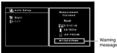
①Check for the blinking of the front display's indicator to identify the problem speaker.
Problem speaker (blinks)

②Check the cable connections (+/-) of the problem speaker.
If the speaker is connected correctly:
You can save the current settings. Proceed to step 3.
If the speaker is connected incorrectly:
Turn off the unit, reconnect the speaker cable, and then try YPAO measurement again.
6 Playing back a BD/DVD
Now let's play back a BD/DVD.
We recommend playing back multichannel audio
(5.1-channel or more) to feel surround sound produced by the unit.
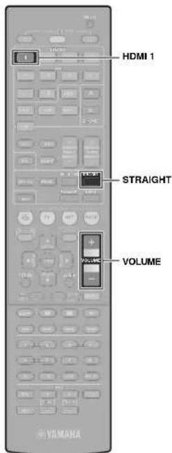
1 Press HDMI 1 to select "HDMI 1" as the input source.

2 Start playback on the BD/DVD player.
3 Press STRAIGHT repeatedly to select "STRAIGHT".


- When "STRAIGHT" (straight decode) is enabled, each speaker produces each channel audio signal directly (without sound field processing).
• (HTR-5065 only) If you play back 5.1-channel audio on the 7.1-channel system, no sounds will be heard from the surround back speakers.
4 Press VOLUME to adjust the volume.

This completes the basic setup procedure.
If surround sound is not working
Sound is only being output from the front speakers during multichannel audio playback
Check the digital audio output setting on the BD/DVD player.
It may be set to 2-channel output (such as PCM).
No sound is coming from a specific speaker
See "Troubleshooting" in "Owner's Manual".
Many more features!
The unit has various other functions. Please refer to "Owner's Manual" on the supplied CD-ROM to help you get the most out of the unit.
Connecting other playback devices
Connect audio devices (such as CD player), game consoles, camcorders, and many others.
Selecting the sound mode
Select the desired sound program (CINEMA DSP) or surround decoder suitable for movies, music, games, sports programs, and other uses.
Playing back from iPod
By using a USB cable supplied with iPod, you can enjoy iPod music on the unit.
■ Listening to FM/AM radio
■Playing back music stored on a USB storage device
■ Playing back the network contents
■ Selecting the input source and favorite settings at once
For more information, see "What you can do with the unit".
(AAA, R03, UM-4) (x2)

□ Antenne AM
□ Antenne FM

□ Microphone YPAO
![Auto Setup Start EXIT Press SETUP key to Start Power Amp Assign Basic + [SETUP]: Start](/content/2026/06/1276756/images/d627a61b86841a0f8a8e703920c67f786fcf76b4cd4d56935c042bed9f425bd0.jpg)


(AAA, R03, UM-4) (x 2)


□ AM-Antenne

□ FM-Antenne

□ YPAO-Mikrofon


(AAA, R03, UM-4) (2 st.)


□ AM-antenn
□ FM-antenn
□ YPAO-mikrofon

□ CD-ROM (Bruksanvisning)
![Auto Setup Start EXIT Press SETUP key to Start Power Amp Assign Basic * [SETUP]: Start](/content/2026/06/1276756/images/cb50c15e11fbfd57a521f20739a9538e709c8db725d8c20edbab3de2888dbd64.jpg)

(AAA, R03, UM-4) (x2)

![Auto Setup Start Exit Please SETUP key to start Power Amp Assign Basic YPAD +[SETUP]:Start](/content/2026/06/1276756/images/bab07053c7f61618adbffd7d10d98dd622f8f22e4ff4df9e5c5cb1ea22564049.jpg)


(AAA, R03, UM-4) (x2)


□ Antena de AM
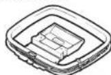
□ Antena de FM

□ Micrófono YPAO

Sistema de 7.1 canales (solo HTR-5065)

FL Altavoz delantero (Izq.)
FR Altavoz delantero (Der.)
C Altavoz central
SL Altavoz surround (lzq.)
SR Altavoz surround (Der.)
SBL Altavoz surround trasero (lzq.)
SBR Altavoz surround trasero (Der.)
SW Subgraves

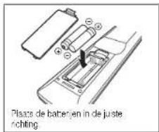
(AAA, R03, UM-4) (x2)

□ AM-antenne

□ FM-antenne

□ YPAO-microfoon

FL Voorste luidspreker (L)
FR Voorste luidspreker (R)
C Middelste luidspreker
SL Surroundluidspreker (L)
SR Surroundluidspreker (R)
SBL Achterste surroundluidspreker (L)
SBR Achterste surroundluidspreker (R)
SW Subwoofer
flowchart
graph TD
    A["Audio-uitgang (optisch)"] --> B["Tv"]
    B --> C["HDMI-ingang HDMI-uitgang"]
    C --> D["HDMI"]
    D --> E["Bd/dvd-speler"]
    B --> F["HDMI 1-aansluiting"]
    F --> G["HDMI"]
    G --> H["HVDC"]
    H --> I["HVDC"]
    I --> J["HVDC"]
    J --> K["HVDC"]
    K --> L["HVDC"]
    L --> M["HVDC"]
    M --> N["HVDC"]
    N --> O["HVDC"]
    O --> P["HVDC"]
    P --> Q["HVDC"]
    Q --> R["HVDC"]
    R --> S["HVDC"]
    S --> T["HVDC"]
    T --> U["HVDC"]
    U --> V["HVDC"]
    V --> W["HVDC"]
    W --> X["HVDC"]
    X --> Y["HVDC"]
    Y --> Z["HVDC"]
    Z --> AA["HVDC"]
    AA --> AB["HVDC"]
    AB --> AC["HVDC"]
    AC --> AD["HVDC"]
    AD --> AE["HVDC"]
    AE --> AF["HVDC"]
    AF --> AG["HVDC"]
    AG --> AH["HVDC"]
    AH --> AI["HVDC"]
    AI --> AJ["HVDC"]
    AJ --> AK["HVDC"]
    AK --> AL["HVDC"]
    AL --> AM["HVDC"]
    AM --> AN["HVDC"]
    AN --> AO["HVDC"]
    AO --> AP["HVDC"]
    AP --> AQ["HVDC"]
    AQ --> AR["HVDC"]
    AR --> AS["HVDC"]
    AS --> AT["HVDC"]
    AT --> AU["HVDC"]
    AU --> AV["HVDC"]
    AV --> AW["HVDC"]
    AW --> AX["HVDC"]
    AX --> AY["HVDC"]


© 2012 Yamaha Corporation Printed in Malaysia ZA52710
- Preparation
- Accessories
- Cables required for connections
- Placing speakers
- Connecting speakers/subwoofer
- ■Connecting speaker cables
- Using a banana plug
- Connect the front speakers (FL/FR) to the FRONT (L/®) terminals.
- Connect the center speaker (C) to the CENTER terminal.
- Connecting external devices
- Connect external devices to the unit.
- Turn on the unit, the TV and the BD/DVD player.
- Use the TV remote control to change the TV input to video from the unit.
- Optimizing the speaker settings automatically (YPAO)
- Connect the YPAO microphone to the YPAO MIC jack on the front panel.
- To start the measurement, press SETUP.
- Use the cursor keys (◀/▶) to select "SAVE" (Save) and press ENTER.
- Disconnect the YPAO microphone from the unit.
- If "W-1:Out of Phase" appears
- If the speaker is connected correctly:
- If the speaker is connected incorrectly:
- Playing back a BD/DVD
- If surround sound is not working
- Many more features!
- Connecting other playback devices
- Selecting the sound mode
- Playing back from iPod
Brand : YAMAHA
Model : HTR-4065
Category : Receiver