
LU 115 HF - Motion detector THEBEN - Free user manual and instructions
Find the device manual for free LU 115 HF THEBEN in PDF.
| Product type | HF motion detector (high frequency) |
| Brand | THEBEN |
| Model | LU 115 HF |
| Power supply | 6 V DC batteries (AA 1.5 V x 4) or mains adapter (6-9 V DC) |
| Rated voltage | 6 V DC (batteries) or 6-9 V DC (adapter) |
| Transmission frequency | 433.92 MHz |
| Modulation | ASK (Amplitude Shift Keying) |
| Transmission range | Approx. 50 m in open air |
| Detection range | 1 m x 5 m (installation at 5 m) or 0.6 m x 3 m (installation at 3 m) |
| Maximum detection distance | Up to 8 m (adjustable) |
| Brightness setting (LUX) | Adjustable from 5 LUX to infinity |
| Distance setting (METER) | Adjustable from minimum to maximum range (approx. 1 m to 8 m) |
| Number of channels | 256 combinations (HF coding selector and coding selector) |
| Protection type | IP44 (suitable for outdoor use) |
| Operating temperature | -20 °C to +45 °C |
| Battery life | Approx. 6 months (for 10 activations per day at 20 °C) |
| Package contents | Transmitter, table stand, manual, 2 wood screws dia. 4 x 25.4 mm |
| Main functions | Passive infrared detection, wireless transmitter with signal LED, LUX and distance settings, wall/ceiling/table/door frame installation |
| Possible installation | Door frame, ceiling, wall, table, door corner (optimal height 3-5 m) |
| Maintenance and cleaning | Clean with a soft, dry cloth. Do not use abrasive products. |
| Safety | Use only new alkaline batteries; observe polarity; use the original adapter; do not install near heat sources or highly reflective surfaces. |
| Spare parts and repairability | No replaceable parts available. In case of malfunction, contact the manufacturer. |
| General information | Compliant with EU directives (DBT & EMC) and R&TTE. Compatible with other Theben HF products at 433.92 MHz. |
Frequently Asked Questions - LU 115 HF THEBEN
User questions about LU 115 HF THEBEN
0 question about this device. Answer the ones you know or ask your own.
Ask a new question about this device
Download the instructions for your Motion detector in PDF format for free! Find your manual LU 115 HF - THEBEN and take your electronic device back in hand. On this page are published all the documents necessary for the use of your device. LU 115 HF by THEBEN.
USER MANUAL LU 115 HF THEBEN
DC 6V (AA1.5V x 4) battery
Transmission Range:
or AC adaptor (DC 6-9V - - - +)
Transmission Frequency:
Approx. 50M (in open air)
Modulation:
433.92MHz.
- Channel:
ASK
- Detecting Range:
256 combinations
1 m x 5 m (at 5 m height)
or 0,6m× 3m (at 3m height)
- Meter:
Adjustable up to about 8 m
LUX:
Adjustable from about 5 LUX to ∞
- Battery Life:
About 6 Months
(By 10 activations per day at 20ircC )
Operation Temperature:
-20° C ~ +45° C
- Environment Protection:
IP 44
PACKAGE CONTENTS
| Pattern | ||||
| Item | Transmitter | Table stand | Manual | Wood screw 4 x 25,4 mm |
| Quantity | 1 | 1 | 1 | 2 |
13
INTRODUCTION
LU 101/115 HF is a transmitter that combines infrared sensor and wireless feature. LU 101/115 HF is for short-distance detection, which is up to 8M, and it is ideal for installation on the door gate, ceiling and wall, or put on the table.
When receiver receives the signal transmitted by LU 101/115 HF the receiver sends out sound to notify users visitors' coming or the family members' going out, or to announce the arriving of visitors by flash light. In these ways, users can show welcome to guests timely, conveniently and politely.
Apart from the features above, Transmitter LU 101/115 HF has other remarkable functions as following:
- Easy installation on door gate, ceiling, wall, table... etc, and simple operation.
- Adjust the detection range by rotating 90irc on right or left.
- Full compatibility with all WAVEMAN products.
- Wire free and convenient.
- Apply to different locations: offices, small-scaled stores and homes ...etc.
14
CHANNEL SET-UP
Transmitter and receiver communicate each other by having the same channel.
Transmitter LU 101/115 HF has been preset its system channel at "I" and unit channel at "9" before exiting factory. Please make sure the channel settings of receiver and transmitter are identical and the transmitter's system channel match the preset of the receiver.
However, if the user finds transmitter LU 101/115 HF and the Receiver have the same channel setting with other wireless device near by, the user DEFINITELY needs to make change on the channel setting.
Do not adjust system channel to "A" position and unit channel to "1" position on all Theben series.
Though Theben series provide 256 combinations for channel settings, the best for the user is to use 255 combinations and exclude one combination-A1 from your channel setting, because A1 is very easy to get interference from other similar product in the market that eventually makes wireless device abnormally working.
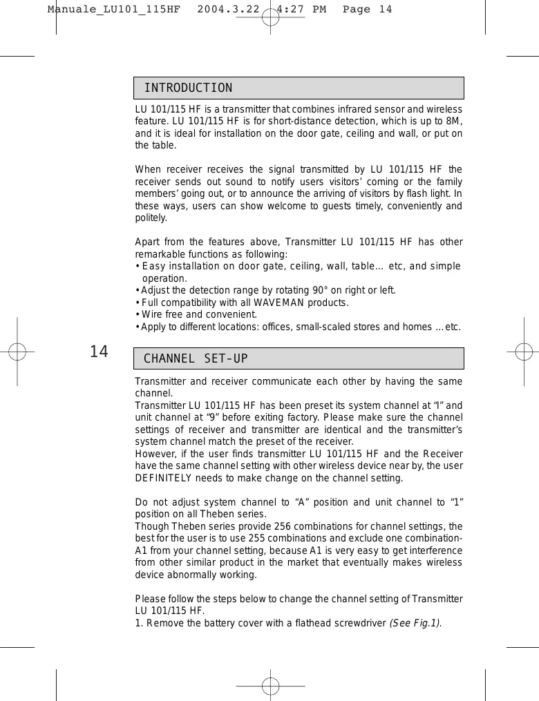
Please follow the steps below to change the channel setting of Transmitter LU 101/115 HF.
-
Remove the battery cover with a flathead screwdriver (See Fig.1).
-
Adjust the channel to a desired position with a screwdriver (See Fig. 2).
- Pull the battery cover back.
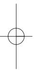
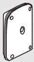
- Please note direction while closing the battery cover. The convex corner of battery cover should be connected to the convex area of sensor body and the small hollow inside battery cover should be placed at the bottom.

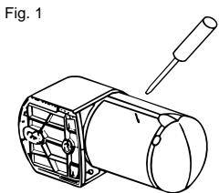
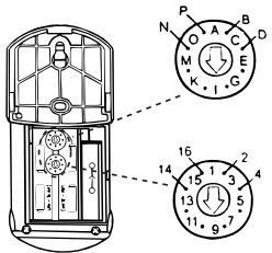
Fig. 2
System channel (House channel)
Unit channel
INSTALLATION
A. Helpful Tips For a Better Transmission
- Install LU 101/115 HF on the ceiling about 3m 5m height from the floor, and LU 101/115 HF on the wall about 0.7m 1.2m from the floor to ensure effective functions.
- Measure the distance between the transmitter and the receiver before installation. Make sure transmitter LU 101/115 HF is mounted in effective working range.
- Avoid installing transmitter LU 101/115 HF near aluminum alloy or thick metal that shortens the transmitting distance. Keep it away at least 1m .
- Avoid installing transmitter LU 101/115 HF on the thick wall or fence, which blocks transmission wave and shortens the remote controlling distance.
- During installation, avoid testing transmitter LU 101/115 HF by holding in hands, due to the human body is one kind of antenna that would cause interference to wireless devices.
- Keep the valid detection range of transmitter LU 101/115 HF cleared, and the surrounding space, respectively in 3m from the transmitter, having no other devices may receive the electric wave from the Transmitter.
- Don't toward LU 101/115 HF sensor body to the sky while installed outside to maintain the water proof feature (See Fig. 3).
Fig. 3
15
B. Select a Proper Location
1. Detection range
(1) Under the standard specification of LU 101/115 HF (1M x 5m at 5M height or 0.6M x 3M at 3M height), the detection range is up to the height of installation, the higher of LU 101/115 HF installed, the wider of detection range resulted (See Fig.4).
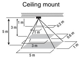
Fig. 4
(2) Choose a proper installing position for Transmitter LU 101/115 HF where it can work excellently with the combined Receiver.
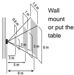
(3) LU 101/115 HF can be mounted on the door gate (See Fig. 5), ceiling (See Fig. 6), door side (See Fig.7/8) or put on the table (See Fig.10), which best height of installation is about 3m 5m from the floor. LU 101/115 HF can be mounted on the wall (See Fig.9) or put on the table only (See Fig.10), which best height of placement is 3m 1.2M from the floor.
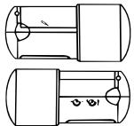
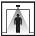
Fig. 5 - Door gate mount
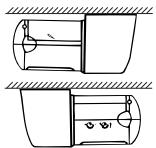
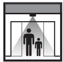
Fig. 6 - Ceiling mount
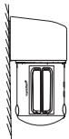
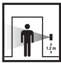
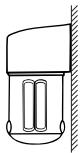
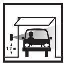
Fig. 7 - Door side mount
Fig. 8 - Door side mount
16
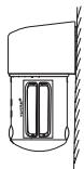
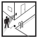
Fig. 9 - Wall mount
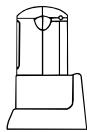
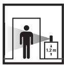
Fig. 10 - Put on the table

Note:
It is normal state that the detection range is divergent in different environment. Suggest not installing LU 101/115 HF in where the end zone is the main detected target
To obtain excellent performance, please mount LU 101/115 HF horizontally on ceiling or the top of door-gate and vertically on wall, table or beside door-gate.
2. Avoid Nuisance Triggering
Transmitter LU 101/115 HF can be activated by any large animals, light reflective surfaces, heat sources or a moving object.
Following guidelines will help you avoid nuisance triggering:
Avoid the object moving directly toward the sensor that brings the less sensitivity of detection. Have the object move across the pattern zone that brings more sensitivity.
- Do not aim the sensor toward any kind of lighting sources.
- Avoid aiming the sensor toward object that moves in the wind such as bushes or lawn decoration.
- Avoid mounting the sensor nearing any sources, such as heating vent, air conditioner, dryer vent or the lighting device.
- Avoid having the sensor toward the area or the object whose surfaces are highly reflective or are subject to rapid changing in temperature, such as the pool ... etc.
17
C. Installation Procedure
LU 101/115 HF can operate by using alkaline battery or connecting AC power by an AC adaptor. Please refer to the following for two methods of power supply:
A) Please follow the steps below to insert new batteries:
1. Remove the battery cover with a flathead screw-driver (See Fig.1).
2. Insert 4 pieces of new AA 1.5V alkaline batteries. Please note that reverse polarity may cause damage on sensor (See Fig.11).
3. Put the battery cover back.
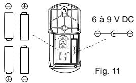
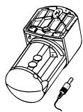
Fig. 12
The battery's lifetime is decided by activating frequency and environmental temperature. The more activating frequencies and the lower environmental temperature is, the sooner of power consumption. In normal circumstances, alkaline battery for transmitter LU 101/115 HF can be used for about 6 months by triggering about 10 times every day at 20irc C operating environment. When the battery is running faded, LED gets faint or the transmission range becomes shorter, please repeat step 1 ~ 3 to use new batteries instead of old ones.
B) It is workable to plug AC power in DC socket instead of batteries. Usually, it is suggested to connect AC power with AC adaptor for economic reason. And in order to make the control unit work normally, please use AC adaptor provided only by original manufacture.
1. Remove the battery cover with a flathead screw-driver (See Fig.1).
2. Plug the AC adaptor in DC socket from the back cover (See Fig.12).
3. Punch the reserved knock hole on battery cover with a long nose pliers (See Fig.13).
4. Put the battery cover back and make sure the wires go through the reserved knock hole (See Fig.14).
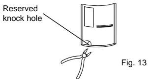
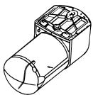
Fig. 14
- It is not waterproof since the reserved knock hole has been broken while using AC adaptor. In order to maintain it in waterproof, you'd better use SILICONE glue to fulfill the reserved knock hole.
- Make sure take out batteries before using AC adaptor.
C) Two methods for LU 101/115 HF installation:
- Fix transmitter LU 101/115 HF on the installing surface with screws.
(1) Unscrew the base which is matched before exiting factory (See Fig.15).
(2) Remove the base (See Fig.16).
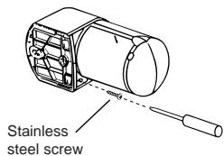
Fig. 15
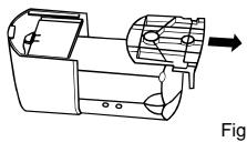
Fig. 16
(3) Fix the base on the installing surface with screws (See Fig.17).
(4) For easy installation, please fasten the top one screw on the wall firstly, then hang the mounting base by the fixed screw on the wall to fasten the second screw orderly (See Fig.18).
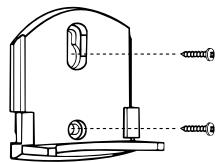
Fig. 17
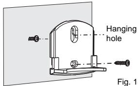
Fig. 18
(5) Insert the main body of transmitter LU 101/115 HF into the fixed base tightly (See Fig.19).
(6) Fasten the base and main body firmly with screw (See Fig. 20).
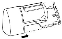
Fig. 19
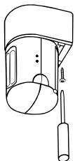
Fig. 20

19
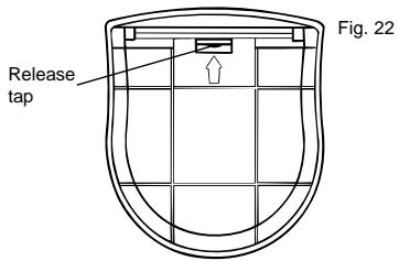
- Put transmitter LU 101/115 HF on the table, insert the main body directly on the bracket that is matched well before exiting factory, then it can work (See Fig. 21). If you want to take apart the bracket, turn over the LU 101/115 HF, then turn the valve in the bottom of the bracket toward outside (See Fig. 22), and another hand take out the main body of LU 101/115 HF
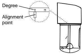
- When users want to adjust the detecting position, hold the protruding head of transmitter LU 101/115 HF, rotate it to an angle desired toward left or right at the range of 90irc (See Fig. 23).
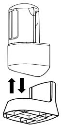
Fig. 21
20
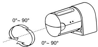
Fig. 23
TEST AND ADJUSTMENT

A. LUX, Meter Knobs
1. LUX
- LUX is adjustable from the range about 5 LUX to ∞ .
- Set LUX knob to " ", the sensor can operate in darkness only.
- Set LUX knob to “ ※ ” the sensor can operate at any light level.
- The more adjustment to close " ", the sensor can operate in more ambient light level
2. Meter
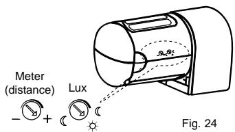
- Setting knob to "-", sensor detects the smallest "field of view".
- Setting knob to "+"sensor detects the largest "field of view" to about 8m (See Fig. 24).
- The more adjustment from " _ " to "+" will extend more distance for detecting zone from about 1m to 8m.
- Suggest setting knob to "+" when LU 101/115 HF is mounted on the ceiling or the top of doorgate.
21
B. LED Function
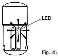
LED (See Fig. 25) is mainly desired as the indication for sensor activation. When environment is applicable for LUX, trigger the transmitter LU 101/115 HF, LED will turn on for about 5 seconds and then turn off.
C. Walk Test
LU 101/115 HF automatically works when power turns on. If it is necessary you can use walk test to test and adjust the detection coverage, which helps to make it work properly. Before the test, adjust LUX to " 心 ", meter to "+" then you can start walk test.
Procedures of walk test:
- Aim the Transmitter LU 101/115 HF across the traffic pattern where you want to detect.
- Warm up the transmitter for about 30 seconds.
-
Make sure the transmitter and the combined receiver have set with the same channel.
-
Check if LED of transmitter LU 101/115 HF works normally.
- Have someone walk across the pattern from outside of coverage until LED turns on.
- When Transmitter LU 101/115 HF is triggered at the first time, LED will turn on for about 2 sec. and send out the signal to receiver, then turn off. It takes about 5 seconds for the transmitter to reactivate. If transmitter keeps being triggered within the 5 seconds (after the first trigger), the time meter will recount. Transmitter will NOT activate, which means it will not send out the signal to the receiver. Transmitter needs to be at non-triggered status for at least 5 seconds after being triggered at first time, then it is able to be activated again.
- The detection zone is adjustable by adjusting meter and sensor head.
- Repeat step 6 to step 8 until the detection coverage zone meets your requirement.
Note: Whatever the meter knob to be adjusted at any position, the farthest of detection range can not be treated as normal detecting area.
TROUBLE SHOOTING
When Transmitter LU 101/115 HF fails to work normally, check presumptive problems and suggested solutions in following table that will hopefully solve your problem.
| Problem | Possible cause | Suggested solutions |
| LU 101/115 HF LED does not turn on. | 1. Low battery or battery is inserted incorrectly. No power supplies. | 1. Make sure the battery is enough and the batteries inserted correctly. |
| Receiver can’t receive signals. | 1. Different channel setting between transmitter and Receiver. | 1. Make sure the channels of transmitter and receiver are set at the same channels. |
| 2. Exceeding effective working range. | 2. Make sure transmitter and receiver are in effective working range. |
EXTENSION OF LU 101/115 HF
Transmitter LU 101/115 HF is fully compatible with other RF series product whose frequency at 433.92MHz that allows the user to integrate any desired quantities either same or different model from WAVEMAN series. Transmitter LU 101/115 HF to build up a specific user network of transmitters and receivers at home, office and small-scaled store or factory. Please refer to the following chart which are some illustrations of typical combination between the transmitter of LU 101/115 HF and WAVEMAN receiver.

Transmitter
LU 101/115 HF
Motion
sensor transmitter
Receiver
REC 100 HF
Outdoor / Indoor
10A Receiver
C∈APPROVAL
C∈0560①
| N | DK | SF | IS | S |
| E | D | F | P | I |
| B | NL | L | GR | GB |
| IRL | CH | A |
23
Remarks:
- Theben HF products are allowed to sell to all EU and EFTA countries.
- The receiver complies with essential safety and radio frequency with CE (LVD & EMC) and R & TTE directives.

LU 101/115 HF
RILEVATORE DI MOVIMENTO HF

SPECIFICHE TECNICHE
- PACKAGE CONTENTS
- INTRODUCTION
- CHANNEL SET-UP
- INSTALLATION
- Helpful Tips For a Better Transmission
- Select a Proper Location
- Detection range
- Note:
- Avoid Nuisance Triggering
- Installation Procedure
- TEST AND ADJUSTMENT
- LUX, Meter Knobs
- LUX
- Meter
- LED Function
- Walk Test
- TROUBLE SHOOTING
- EXTENSION OF LU 101/115 HF
- Transmitter
- LU 101/115 HF
- Receiver
- REC 100 HF
- C∈APPROVAL
- C∈0560①
- Remarks:
- SPECIFICHE TECNICHE
Brand : THEBEN
Model : LU 115 HF
Category : Motion detector