
ECO-IR 180A@ECO-IR 360A - Motion detector THEBEN - Free user manual and instructions
Find the device manual for free ECO-IR 180A@ECO-IR 360A THEBEN in PDF.
| Brand | THEBEN |
| Model | ECO-IR 180A / ECO-IR 360A |
| Product type | PIR presence detector |
| Power supply | 230 V AC |
| Outputs | 2 independent relays: Light (230V / 6A~) and HVAC (potential-free, 50V= 2A, 230V~ 2A) |
| Detection range (180A) | Horizontal 180°, vertical 55°, radius 10 m |
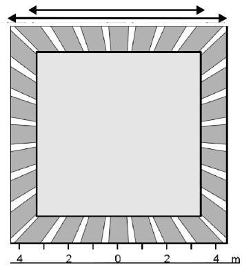
| Detection range (360A) | Horizontal 360°, vertical 120°, area 8x8 m (2.5 m) / 9x9 m (3 m) |
| Mounting height (180A) | 1.6 to 2.2 m |
| Mounting height (360A) | 2.0 to 3.5 m |
| Light switch-off delay | 2 to 15 min (adjustable), 2 min = fixed |
| HVAC switch-off delay | 10 to 60 min (adjustable) |
| Daylight monitoring | Approx. 50 to 1600 Lux |
| Protection rating | IP 40 (indoor) |
| Ambient temperature | 0 °C to 50 °C |
| Protection class | II (EN 60730-1) |
| Flush-mounting box (diameter) | Ø 58 mm |
| Box depth | 35 mm |
| Terminals | Screwless, for conductors up to 1.5 mm² |
| Maintenance | Clean the lens with a soft, lint-free cloth. Do not open the device. |
| Safety | Installation by a qualified electrician. Disconnect power before any intervention. |
| Spare parts | Sensor module available separately (ref. 20 180 002 for 180A, 20 360 002 for 360A) |
| Warranty | 1 year from invoice date |
| Repairability | Repair only by HTS or authorized distributor |
| General information | Presence detector for lighting and HVAC control. Indoor use. |
Frequently Asked Questions - ECO-IR 180A@ECO-IR 360A THEBEN
1. The Lux value may be too low: increase it.
2. The detection field may be obstructed or not covering the area: change the location or remove obstacles.
3. A sensor component could be defective.
4. The lamp power supply may be interrupted (switch set to 'ON').
1. The Lux value is too high: reduce it.
2. Sudden heat sources (radiator, halogen lamp) or moving objects (curtains, animals) trigger the detector.
3. Inductive loads (contactors) must be suppressed with RC elements.
4. In case of parallel switching of several detectors, check the Lux setting.
5. Reset the device by disconnecting and reconnecting it.
User questions about ECO-IR 180A@ECO-IR 360A THEBEN
0 question about this device. Answer the ones you know or ask your own.
Ask a new question about this device
Download the instructions for your Motion detector in PDF format for free! Find your manual ECO-IR 180A@ECO-IR 360A - THEBEN and take your electronic device back in hand. On this page are published all the documents necessary for the use of your device. ECO-IR 180A@ECO-IR 360A by THEBEN.
USER MANUAL ECO-IR 180A@ECO-IR 360A THEBEN
High Technology Systems
ECO-IR® 180A
Produktbeschreibung
The ECO-IR® is a multi-functional passive, infrared presence detector (PIR technology) that detects the presence of persons and measures the incident daylight.
The device is equipped with two independent outputs (relay contacts) for controlling lighting, heating, ventilation and air-conditioning (HVAC) systems. The lighting conditions are adapted to the current requirements by means of the "Light" switching contact. The potential free "HVAC" switching contact controls electrical loads depending on whether persons are present in the room, irrespective of the lighting conditions.
ECO-IR 180A/360A
ECO-IR 180A
6
ECO-IR 360A
7
You have just purchased a device from HTS. Thank you for placing your trust in us. Our technically advanced products will only function correctly if
their use has been carefully planned
- they are mounted and connected in accordance with the operating instructions
they are put into operation in accordance with the specified instructions
- the user is familiar with the functioning of the device.
We hereby confirm that the CE symbol has been used by HTS in pursuant to the EN 50 081-1, EN 50 082-1 and EN 60 669 guidelines.

IMPORTANT
Do not open the device. The device does not contain any components that can be maintained by the customer. The warranty is no longer valid if the device is opened.
Contents
1 Safety
2 Function and performance characteristics
3 Mounting and connecting the device
4 Applications
5 Putting the device into operation
6 Warranty
7 Copyright
8 Troubleshooting
9 Technical data (rear of instruction manual)
17 Safety

Danger
All work on the 230V power supply must be performed by authorized trained personnel only. Incorrect handling of the device can lead to serious injury or cause
damage to the ECO-IR. Always disconnect the power supply before mounting/dismounting the ECO-IR. The national and local specifications for handling electrical equipment must always be observed.
Read the operating instructions carefully before mounting or putting the ECO-IR into operation.
ECO-IR presence detectors may only be used indoors (system of protection IP 40).
The sensors must be secured firmly with the safety locking device after the upper part has been connected (Fig. 3).
18 Function and performance characteristics
18.1 Presence detection High-sensitivity PIR sensors and an intelligent lens system provide complete coverage.
18.2 Integrated daylight measurement Measures the exact amount of daylight independently of the artificial lighting conditions. The measurement is performed in the viewing direction of the device. Delayed response to brightness changes to prevent unnecessary activation/deactivation.
18.3 "Light" switching contact The switching contact closes if the brightness level is too low and if the presence of a person is detected. It opens if the brightness level is adequate or if no presence is detected. The switch-off delay time and desired switching value can be defined as required.

Important
The ECO-IR is designed for use in combination with fluorescent lamps (FL operates with standard ballasts) and energy saving lamps (PL). When using normal incandescent or halogen lamps the daylight measuring is restricted (ask supplier).
With indirect lighting, ensure that the main part of the light from these lamps is not directed at the detector as this affects the daylight measurement.
When using suspended lighting, we recommend that you integrate the detector directly in the lamps or provide a sufficient lateral clearance.
When using suspended lighting, note that the detection range may be shaded.
18.4 "HVAC" switching contact
A potential free relay connects loads up to max. 100 W. The loads are only connected if a person is detected, independent of the incident daylight. The contact is closed if persons are detected.
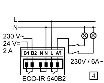
18.5 "Light" switch-off delay time (Fig. 2)
You can set the minimum duration to between 2 and 15 minutes. The ECO-IR can extend this time setting (by max. 15 minutes) or reduce it to the minimum value, depending on the frequency of movement (self-learning effect). When set to 2 minutes, the switch-off delay is fixed.
18.6 "HVAC" switch-off delay time (Fig. 2)
You can set the duration stepplessly to between 10 and 60 minutes.
Unlike the "Light" switch-off delay time, the "HVAC" switch-off delay time is not adjusted by the ECO-IR.

Note
The switch-off delay times are restarted each time a movement is detected. When set to 2 min, the switch-off delay is fixed, there is no selflearning effect, the switch-off delay remains constant.
19 Mounting and connecting the device
19.1 Type of mounting
Both ECO-IR models must be mounted in housings (surface-mounted or concealed installation, single housing) (Fig. 1a, 1b).
Suitable hollow-wall housings must be provided for mounting the devices in suspended ceilings.
19.2 Preparations
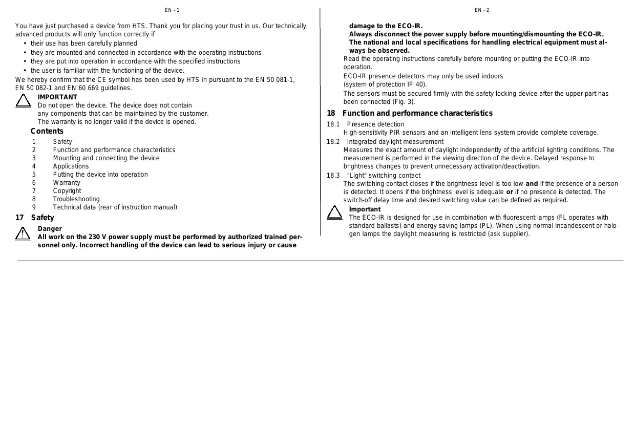
First pull out the left and right-hand safety locks up to the limit stop using a screwdriver to separate the sensor head from the power section (Fig. 3).
Remove the sensor head (white) from the power section (black).
19.3 Connecting the ECO-IR
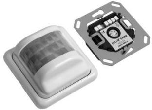
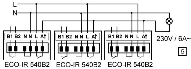
Connect the power section of the ECO-IR 540B2 as shown in the diagram (Fig. 4, 5):
- Neutral to N
- Phase to L
- Phase connected to Ahat
-HVACtoB1,B2
19.4 Connecting several units in parallel
The outputs (A) of several ECO-IR units can be connected in parallel as shown in Fig. 5.

Important
All of the ECO-IR units connected in parallel must be connected to the same mains phase. The overall permissible load as a result of the parallel connection is not higher.
19.5 Manual OFF circuit
If the automatic function of the lighting system is to be deliberately overridden, a conventional switch should be connected to the output circuit downstream of the ECO-IR (Fig. 4).
19.6 Stepping switch/time switches
The ECO-IR must not be used to trigger stepping switches. The unit may only be connected in parallel to time switches.
19.7 Connections via external relays
External contactors or relays must be used to connect loads >1.4kVA to the "Light" output.

Important
Inductive loads must be interference-suppressed with suitable spark extinguishers (e.g. RC combination)
20 Applications
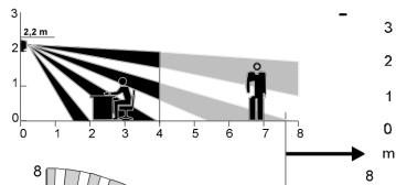
ECO-IR 180A for wall mounting
Detection range: 180^ (horizontal), 55^ (vertical)
(Fig. 6). The recommended mounting height is 2.2m
The ECO-IR 180A can also be mounted on the ceiling in corridors. Please note the detection range or ask for planning documentation.
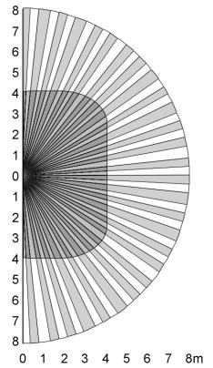
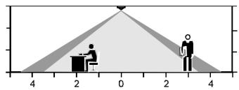
ECO-IR 360A for ceiling mounting (e.g. for detecting persons also when seated).
Detection range: 360^ (horizontal), 120^ (vertical) (Fig. 7). The ideal mounting height is 2 - 3.5

Important
The detection range is reduced accordingly if the ECO-IR 360A is mounted at a lower position. When mounted higer than 3.5m , larger movements are required and the detection areas of multiple detectors should overlap at their edges.
In order to ensure that persons are detected correctly, the detection range must not be impaired by office equipment, partitions, plants etc. (shading).

Note
ECO-IR presence detectors should not be used as alarms.
21 Putting the device into operation
Set the unit as shown on the rear of the disassembled sensor head.
Note the setting guidelines in the following table (see also Fig. 2) for defining the default settings.
"HVAC" switch-off delay time

- Set the desired switch-off delay time for the "HVAC" switching contact on the "Time minutes" potentiometer. The settings are not modified.
The switch-off delay time varies depending on application and load.
10 - 60 min.
"Light" switch-off delay time
- Set the desired minimum switch-off delay time for the "Light" switching contact on the "Min. time minutes" potentiometer.
| The setting corresponds to the minimum value. The effective switch-off delay time varies between the set value and the maximum value of 15 min. (self-learning eff.). When set to 2 min., the switch-off delay is fixed. | |
| Rooms that are seldom or briefly frequented. Detection of movements, not seated persons, rooms with clear overview. Short lighting time required. | < 5 min. |
| Detection of seated persons, moderate movement (offices, assembly bays, recreation rooms etc.) | 7.5 min |
| Detection of seated persons with low movement, rooms without a clear overview, difficult activities, large distance from detector (reading rooms, laboratories, workshops, high-precision assembly areas, computer rooms etc.) | > 10 min. |
| "LUX" brightness switching value ● Set the brightness switching value on the "Lux" potentiometer. | |
| The specified values are simply intended as guidelines. It may be necessary to correct the setting by 1 - 2 scale divisions depending on the mounting location (proximity of windows), incident light, furniture, reflective properties of the floor and walls, glare caused by lights, sensitivity to light of the user etc. | |
| Passageways, excluding work areas (traffic zones, corridors etc.) | appr. scale 2 |
| Work areas(Offices, Workshops, conference rooms, storage bays, schools) | appr. scale 4 |
Visually intensive activities
(high-precision assembly areas, workshops, drawing rooms etc.)
No daylight effects required or no daylight present. Brightness measurement is deactivated.
Scale >6
on
- After you have defined the settings, connect the upper part to the power section. Ensure that the labeling is aligned on both parts.
Each time the sensor head is attached to the power section or after the power supply is connected, a startup phase (90 sec.) followed by a service phase (10 min.) is initiated on the sensor. The sensor then switches to normal operation automatically.

Important
Avoid using force when assembling the unit. Ensure that the two parts are aligned correctly. Do not press on the lens. Hold the upper part at the white edge only.
- The two switching contacts are closed for approx. 90 sec. after the unit has been assembled (startup phase). The lighting system lights up continuously and the ventilation system is in operation.
- In the subsequent service phase, the ECO-IR responds immediately to changes in brightness in order to test the set brightness switching value (Lux) quickly. If the room is darkened (e.g. by closing the blinds), the lighting system is switched on when the switching value is reached. The lights can be switched off by "blinding" the sensor with a torch. The service phase is completed automatically after 10 minutes.
- Repeat the setting procedure if it is necessary to modify one of the three variables.
-
push the safety lock inwards as far as possible after the test (between the sensor head and the power section) (Fig. 3). The detector is then ready for operation.
-
Disassembling/readjusting the unit. If you want to disassemble the head section or change the settings, first open the safety locks by pulling out the two locks with a screwdriver.
22 Warranty
HTS presence detectors are manufactured and quality-tested with high precision and using modern technologies. HTS therefore guarantees that all of the models in the ECO-IR series will function correctly provided that they are used in the prescribed manner. Should the system prove to be defective, however, HTS will provide the following warranty:
The warranty period is 1 year from the date of invoice.
The warranty is excluded if the goods supplied become damaged due to improper handling or are used in a manner contrary to the specifications, standards and instructions, in particular, contained in the product description. The warranty obligation is limited to Europe. The warranty and liability with regard to subsequent damage to the assembled device for devices integrated in a software-controlled system are limited to maintenance of the interface specification. Liability for subsequent damages as a result of defects is excluded. The general terms and conditions of HTS apply as do the Swiss Obligation Rights.
Liability for damage does not include damage due to transportation or damage as a result of non-compliance with the specifications contained in the operating instructions or with the instructions for correct installation.
HTS must be allowed the time and opportunity required to rectify the defect.
Submission
In the event of a warranty claim, the device should be sent with the delivery certificate and a brief description of the fault to the relevant dealer or, if purchased directly, to HTS.
23 Copyright
The design, hardware and software of these devices are protected by patent.
ECO-IR® is a registered trademark, the use of which is subject to the approval of HTS.
24 Troubleshooting
| Fault | Cause | Remedy |
| Lighting system on after the detector is connected. | Both outputs are closed for 90 s after the detector has been connected (test phase) | Wait for 90 s. The device then responds immediately to changes in brightness for 10 minutes. |
| The detector does not switch off after 90 s | The detector may respond more slowly in accordance with the switch-off delay time | Wait until the switch-off delay time has elapsed |
| Immediate response to change in brightness | The device is in service phase (10 minutes) This phase is used to adjust the brightness setting | Test: "blind" with torch → lights off. Darken (e.g. with blinds) → lights on. After the service phase, the system response to a change in brightness is delayed to prevent sudden activation / deactivation. |
| Lights never switched on, despite presence of persons and little daylight | 1. Lux value too low.2. Detection zone does not cover the entire room Vision may be impaired.3. No sensitivity setting4. Lamp supply line interrupted by switch. | 1. Increase Lux value.2. Change mounting location or remove obstacles in detection range.3. Sensor element may be defective.4. Set switch to "ON". |
| Lights flash constantly | 1. Incandescent lamps triggered by ECO-IR. | 1. See section 2.3, set Lux value to "on" or replace incandescent lamps with FL/PL lamps.2. See section 2.3, check arrange- |
| Fault | Cause | Remedy |
| tor from fluorescent lamps too high. | ment of detector with regard to lamps. | |
| Lights on continuously / detector switches without reason | 1. Lux value too high. | 1. Decrease Lux value. |
| 2. Other movements have been registered. | 2. Switch off devices with instant heat emission (e.g. heater, halogen spots, incandescent lamps), close open doors and windows, are other moving objects (curtains, suspended signs) or domestic animals present? | |
| 3. External contactor or relay triggered | 3. Inductive loads must be fitted with suitable spark extinguishers by qualified technicians (e.g. RC element). | |
| 4. Several detectors connected in parallel | 4. Check Lux setting on detectors | |
| 5. "Self-learning effect" | 5. Remove ECO-IR and connect it again, repeat initialization. | |
| Lights extinguish despite presence of persons | Minimum switch-off delay time too low | Check recommended settings, increase switch-off delay time. |
| Lights extinguish too late after the room is vacated | Minimum switch-off delay time too high | Reduce switch-off delay time. See section 2.5 in these instructions → self-learning adjustment of switch-off delay time. |
| Detection zone is smaller than specified | 1. Objects in visibility range | |
| 2. Detector positioned incorrectly |
11030 00305 05/00 © by HTS