
OTG100SLB6 - Boiler GORENJE - Free user manual and instructions
Find the device manual for free OTG100SLB6 GORENJE in PDF.


| Product type | Wall-mounted gas boiler |
| Brand | Gorenje |
| Model | OTG100SLB6 |
| Dimensions (W x H x D) | 400 x 700 x 300 mm |
| Weight | 28 kg |
| Power supply | Natural gas (G20) / Propane (G31) - 230 V ~ 50 Hz |
| Nominal power | 24 kW |
| Efficiency | Up to 93 % (NCV) |
| Heating temperature range | 30 °C to 80 °C |
| Domestic hot water temperature range | 35 °C to 60 °C |
| Domestic hot water flow rate (ΔT=30°C) | 13.5 L/min |
| Operating pressure | 1 to 3 bars |
| Energy class | A (heating) / A (DHW) |
| Noise level | 52 dB(A) |
| Main functions | Central heating and instantaneous domestic hot water production, electronic regulation, digital display |
| Safety functions | Overheating safety device, low water safety, frost protection, flame control, draught safety |
| Maintenance and cleaning | External cleaning with damp cloth, annual draining by professional, water pressure check |
| Spare parts and repairability | Parts available on the manufacturer's website or authorized after-sales service |
| General information | Manual available in several languages, free PDF download |
Frequently Asked Questions - OTG100SLB6 GORENJE
User questions about OTG100SLB6 GORENJE
0 question about this device. Answer the ones you know or ask your own.
Ask a new question about this device
Download the instructions for your Boiler in PDF format for free! Find your manual OTG100SLB6 - GORENJE and take your electronic device back in hand. On this page are published all the documents necessary for the use of your device. OTG100SLB6 by GORENJE.
USER MANUAL OTG100SLB6 GORENJE
OTG 30-120 SLIM
Instructions for Use 16
Upute za upotrebu 20
Návod k obsluze 24
Dear buyer, we thank you for purchase of our product.
PLEASE READ THE INSTRUCTIONS THOROUGHLY PRIOR TO THE INSTALLATION AND FIRST USE OF THE WATER HEATER.
THIS APPLIANCE IS NOT INTENDED FOR USE BY PERSONS (INCLUDING CHILDREN) WITH REDUCED PHYSICAL, SENSORY OR MENTAL CAPABILITIES, OR LACK OF EXPERIENCE AND KNOWLEDGE, UNLESS THEY HAVE BEEN GIVEN SUPERVISION OR INSTRUCTION CONCERNING USE OF THE APPLIANCE BY PERSON RESPONSIBLE FOR THEIR SAFETY.
CHILDREN SHOULD BE SUPERVISED TO ENSURE THAT THEY DO NOT PLAY WITH THE APPLIANCE.
This water heater has been manufactured in compliance with the relevant standards and tested by the relevant authorities as indicated by the Safety Certificate and the Electromagnetic Compatibility Certificate. Its basic technical properties are stated upon the nameplate, glued between the connection pipes. The water heater may be connected to water and electric power supply only by a qualified specialist. The reach in its inside due to the repair or removal of limestone and checking and replacement of anti-corrosion protection anode may be performed only by an authorised service workshop.
INSTALLATION
The water heater should be installed as close as possible to the points of use to avoid heat dispersion along the pipes. It should be fastened to the wall with appropriate bolts with minimum diameter of 8 mm. In case the wall in question cannot support the weight three times that of the heater filled with water, the relevant section of the wall (where the heater is to be installed) must be suitably reinforced. OTG water heater must be mounted to the wall in the upright position.
TECHNICAL PROPERTIES OF THE APPLIANCE
| Type | OTG 30 N | OTG 50 N | OTG 65 N | OTG 80 N | OTG 100 N | OTG 120 N | |
| Model OTG 30 | SLIM | OTG 50 SLIM | OTG 65 SLIM | OTG 80 SLIM | OTG 100 SLIM | OTG 120 SLIM | |
| Volume [l] | 30 50 65 80 100 | 120 | |||||
| Rated pressure [MPa] | 0,6 | ||||||
| Weight / Filled with water [kg] | 19/49 | 24/74 | 28/93 | 31/111 | 36/136 | 41/161 | |
| Anti-corrosion protection of tank | Enameled / Mg Anode | ||||||
| Connected power [W] | 2000 | ||||||
| Voltage [V~] | 230 | ||||||
| Degree of protection | I | ||||||
| Grad des Apparatschutzes | IP 24 | ||||||
| Heating time to 75°C 1) [h] | 105 | 155 | 230 | 305 | 355 | 435 | |
| Quantity of mixed water at 40°C [l] | 58 | 94 | 124 | 148 | 194 | 226 | |
| Energy consumption 2) [kWh/24h] | 0,90 | 0,99 | 1,13 | 1,26 | 1,71 | 1,81 | |
1) Time for heating of the whole volume of heater with electric immersion heater by entering temperature of cold water from water supply 15° C.
2) Energy consumption to maintain stable temperature of water in the water heater 65° C at surrounding temperature 20° C, measured according to DIN 44532.
| A B C | |||
| OTG 30 5 | 10 310 2 | 35 | |
| OTG 50 6 | 90 470 2 | 50 | |
| OTG 65 8 | 20 605 2 | 45 | |
| OTG 80 9 | 50 735 2 | 45 | |
| OTG 100 | 1125 900 | 255 | |
| OTG 120 | 1300 | 900 4 | 30 |
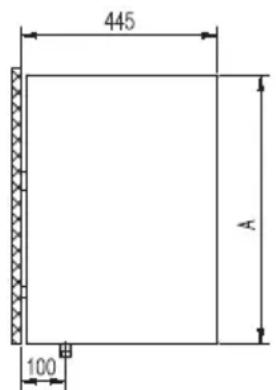
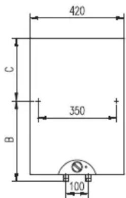
GB
Dimensions of the water heater for installation and connection [mm]
CONNECTION TO THE WATER SUPPLY
The water heater connections for the in-flowing and out-flowing water are colour-coded.
The connection for the supply of cold water is coloured blue, while the hot water outlet is coloured red.
The water heater may be connected to the water supply in two ways. The closed-circuit pressure system enables several points of use, while the open-circuit gravity system enables a single point of use only. The mixer taps must also be purchased in accordance with the selected installation mode.
The open-circuit gravity system requires the installation of a non-return valve in order to prevent the water from draining out of the tank in the event of the water supply running dry or being shut down. This installation mode requires the use of an instantaneous mixer tap. As the heating of water expands its volume, this causes the tap to drip. The dripping cannot be stopped by tightening it further; on the contrary, the tightening can only damage the tap.
The closed-circuit pressure system requires the use of pressure mixer taps. For safety reasons the supply pipe must be fitted with a return safety valve or alternatively, a valve of the safety class that prevents the pressure in the tank from exceeding the nominal pressure by more than 0.1 MPa.
The heating of water in the heater causes the pressure in the tank to increase to the level set by the safety valve. As the water cannot return to the water supply system, this can result in the dripping from the outlet of the safety valve. The drip can be piped to the drain by installing a catching unit just below the safety valve. The drain installed below the safety valve outlet must be piped down vertically and located in the environment that is free from the onset of freezing conditions.
In case the existing plumbing does not enable you to pipe the dripping water from the return safety valve into the drain, you can avoid the dripping by installing a 3-litre expansion tank on the inlet water pipe of the boiler.
You should ensure that the return safety valve is functioning properly by checking it on a regular basis i.e. every 14 days. To check the valve, you should open the outlet of the return safety valve by turning the handle or unscrewing the nut of the valve (depending on the type of the valve). The valve is operating properly if the water comes out of the nozzle when the outlet is open.
![graph LR A["Top Tank"] --> B["Flow Line"] B --> C["Component 1: Pressure Gauge"] C --> D["Component 2: Valve"] D --> E["Component 3: U-shaped Valve"] E --> F["Component 4: Triangle"] F --> G["Component 5: Triangle"] G --> H["Output H"] style A fill:#f9f,stroke:#333 style H fill:#ccf,stroke:#333 note…](/content/2026/06/1273163/images/b07364fe49891305f8727cc2b2ec2ffa89e3b3d54a14857072f2115bc969b38d.jpg)
![graph TD A["Open (non-pressure) system"] --> B["Valve"] B --> C["T"] B --> D["H"] C --> E["Component 3"] D --> F["Component 5"]](/content/2026/06/1273163/images/0c484968a828bbb8ec05e8346eda895687b08aed5437021df183ec2fd340e8c2.jpg)
Legend: 1- Return safety valve 6- Checking fitting
2- Bimetallic fuse
7- Funnel with outlet connection
3- Non-return valve
4- Pressure reduction valve
H - Cold water
5- Closing valve
T - Hot water
Between the water heater and return safety valve no closing valve may be built-in because with it the function of return safety valve would be impeded.
The water heater may be connected to the water network in the house without reduction valve if the pressure in the network is lower than 0.5 MPa (5 bar). If the pressure exceeds 0.5 MPa (5 bar), a reduction valve must be installed. Prior to the electric connection the water heater must obligatorily be filled with water. By first filling the tap for the hot water upon the mixing tap must be opened. When the heater is filled with water, the water starts to run through the outlet pipe of the mixing tap.
POWER CONNECTION
The power lead must be fitted to the water heater prior to being connected to the power supply. In order to do this you should first unscrew the protective cover off the water heater. The water heater must be connected to the power supply in accordance with the requirements set out in the relevant standards applying to electrical installations. For safety reasons a switch should be installed on the lead connecting the heater to the power grid, i.e. a switch disconnecting both power supply poles with the minimum of 3 mm distance between the open contacts.
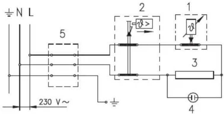
Legend:
1 - Thermostat
2 - Temperature safety device
3 - Heating element
4 - Light indicator
5 - Connector
L - Phase conductor
N - Neutral conductor

- Earth conductor
Electric installation
WARNING: The appliance must be disconnected from the power supply prior to opening and reaching inside the water heater.
USE AND MAINTENANCE
After the connection to water and electric network the heater is ready for use. By turning the knob of thermostat at the front side of the protecting cover, the wished temperature of water between 25° C and 75° C is chosen. We recommend the adjustment of the knob to the position “E”. Such an adjustment is the most economic; with it the temperature of water shall be about 55° C, the excretion of lime-stone and thermal loss shall be smaller as by adjustment to higher temperature.
The operation of electric immersion heaters is shown by pilot light. On the perimeter of the water heater there is a built-in thermometer which is showing the temperature of water.
When the heater shall not be used during a longer time, its contents must be protected against freezing so that the power supply (electricity) shall not be switched off, but the thermostat knob shall be adjusted to the position “*”. With this adjustment the heater shall maintain the water temperature by about 10° C. But when the heater is switched-off from the electric network, at risk for freezing, the water must be emptied from it.
Before draining water heater should be disconnected from main supply. Than hot water valves on taps should be opened. Water heater is to be drained through inlet connection.
For this purpose it is recommendable to put special fitting or a drain valve between inlet connection of water heater and safety valve. If this is not the case water can be drained directly through safety valve by putting the lever or screw cap of safety valve to “Test” position. After draining through inlet pipe there is small quantity of residual water which is to be drained by taking off of heating flange.”
The outside of the water heater is cleaned by a mild solution of detergent. The solvents or rough cleaning means should not be used.
By regular service check of impeccable operation must be assured and a long lifetime of the water heater. The first check must be performed by an authorised service workshop after about two years after the first connection. At check, the use of anti-corrosion protecting anode is checked and if necessary lime stone must be cleaned which with regard to the quality, quantity and temperature of the water used is gathered in the inside of the water heater. Service workshop shall after check recommend also the date of next check of the water heater with regard to the established results.
Never try to repair any possible faults of the water heater by yourself, but inform about it the nearest authorised service workshop.
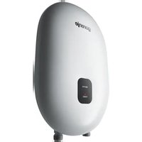


Brand : GORENJE
Model : OTG100SLB6
Category : Boiler