
AZBW20000 - Motion detector ABUS - Free user manual and instructions
Find the device manual for free AZBW20000 ABUS in PDF.


| Product type | Wireless motion detector |
| Brand | ABUS |
| Model | AZBW20000 |
| Dimensions (Length x Width x Height) | 110 x 60 x 45 mm |
| Weight | 95 g |
| Power supply | CR123A battery (included) |
| Detection range | Up to 12 meters |
| Detection angle | 90° horizontal |
| Detection technology | Passive infrared (PIR) |
| Radio frequency | 868 MHz |
| RF range | Up to 100 m in open field |
| Operating temperature | -10 °C to +50 °C |
| Protection rating | IP20 (indoor use only) |
| Main functions | Motion detection, intrusion alarm, communication with ABUS control panel |
| Installation | Wall or bracket mounting, wireless |
| Care and cleaning | Clean with a soft, dry cloth. Do not use chemicals. |
| Security | AES 128-bit encryption for radio transmission |
| Spare parts and repairability | Replaceable battery (CR123A). No user-available spare parts. |
| Warranty | 2 years |
| Package contents | Detector, battery, mounting kit, quick start guide |
Frequently Asked Questions - AZBW20000 ABUS
User questions about AZBW20000 ABUS
0 question about this device. Answer the ones you know or ask your own.
Ask a new question about this device
Download the instructions for your Motion detector in PDF format for free! Find your manual AZBW20000 - ABUS and take your electronic device back in hand. On this page are published all the documents necessary for the use of your device. AZBW20000 by ABUS.
USER MANUAL AZBW20000 ABUS
natural_image
Metallic curved object with a small hole at the bottom, resembling a stylized helmet or mask (no text or symbols visible)
Security Tech Germany
Outdoor motion detector PIR User manual
Abb. 8
natural_image
Pure electrical circuit lines without any symbols
Kleintierimmunität
Höhe: 1,5m
Bereich: Maximal
Neigung: -2°
natural_image
Diagram of a device interior showing internal components and directional arrows, labeled Abb. 9 (no text or symbols on the diagram itself)Programmierung
This outdoor motion detector works with two independent, passive infrared detectors which are located in a housing suitable for outdoor use. Both sensors need to trigger before the detector triggers an alarm signal. This high-precision, reliable detector is designed for use in alarm and video surveillance systems. Pulse counter and detection range can be adjusted from 10 to 30 metres. The detector also features front and rear tampers. The sensor can be panned 180° and tilted 90° in the housing. This increases the performance of outdoor surveillance and ensures extremely precise sensor detection. The PCB has an acrylic coating. Featuring a high quality, shockproof housing and a UV-stabilised, light-permeable front cover which keeps the sensor waterproof and protects against the effects of environment. The combination of precision-electronics, digital white-light filters and double shielding prevents false alarms triggered by sunlight or other interfering sources.
The design of the outdoor motion detector has an attractive, professional appearance, which does not reveal the alignment of the sensor and conceals the wiring completely.
Installation

The electronics must be protected against damp conditions during installation, as this can seriously damage the device. Use the template supplied to drill the holes for the two fastening screws on the cable input wall break contact (if used).
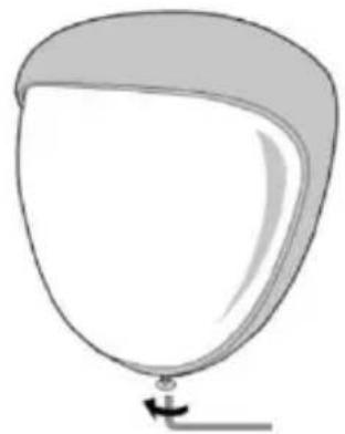
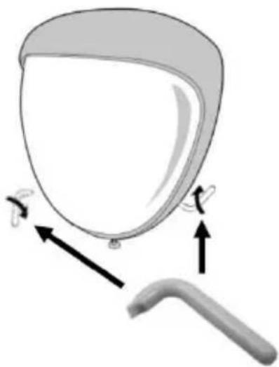
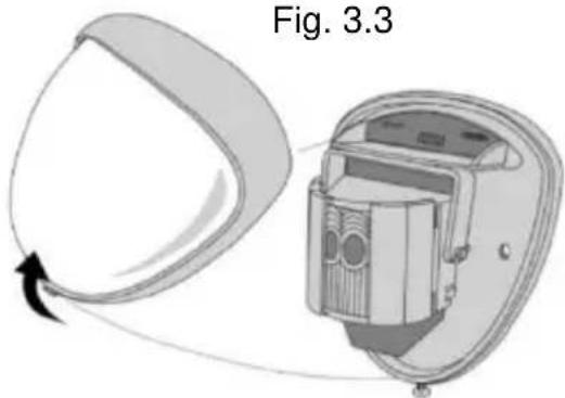
See Fig. 1 and 2. Note: For uneven surfaces we recommend using the adapter for the rear tamper. Remove the front cover of the detector by first loosening the allen screw with the supplied allen key (Fig. 3.1) and then using provided plastic release tool to release the side catches (Fig. 3.2). Once the allen screw and both side catches are released, the cover can be lifted up and out of its groove. (Fig. 3.3)
Fig. 3.1
natural_image
Simple line drawing of a balloon with a handle and small object at the bottom (no text or symbols)Fig. 3.2
natural_image
Diagram of a medical or anatomical component with arrows indicating movement or force (no text or symbols present)Fig. 3.3
natural_image
Diagram of a device with a rotating component and its internal structure, labeled Fig. 3.3 (no text or symbols on the diagram itself)
natural_image
Diagram of a device with cable and connector, labeled Fig. 2 (no text or symbols on the diagram itself)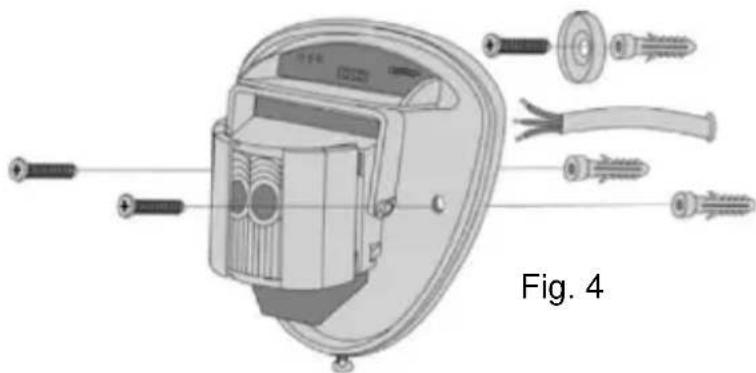
natural_image
Exploded view diagram of an electrical component with screw and cable assembly (no text or labels)Guide the standard 8-wire alarm cable through the cable input. Bare the wires and connect to the detachable terminal block.
Screw the device onto the wall and make sure that the rear tamper is correctly positioned and the switch is closed. See Fig. 4 and 5.
Two tamper feet are supplied as a reserve for the installation. One is 1 mm longer, the other one is 2 mm longer than previously attached. This plug connection can be removed by carefully pulling from the pin. See Fig. 2. When replacing the electronic module, make sure that the LED is facing forwards to ensure the alignment of the sensor is correct (see section on “Beam alignment & bypassing”). When the detector is correctly aligned and installed, replace the front panel and lock it as shown. See Fig. 6.

Connecting the tamper line

Walk test
The range of the detector increases without the front cover. Therefore, this has to be attached for aligning the sensor correctly and checking the outputs. Refer to the table below to adjust the range and pan and tilt the lens module over the area to monitor it completely. When you
press the program button, the blue display lights up and and pulse counter 1 is automatically defined. The device can now be aligned. The blue display on the outdoor motion detector lights up with any detection. The test mode is automatically terminated 5 minutes after the last detection. Otherwise, disconnect the power supply and set the test mode again.
Beam Alignment and Bypassing
In the outdoor motion detector, the multifunction lens generates 7 beams with a long range and a curtain of 7 beams with a range of medium to short. Movements across the beams produce the best response and the largest detection area, while movements in the direction of the detector lead to weaker results. The device detects changes in temperature and movements in the beam pattern. Therefore, objects such as trees, bushes, ponds, heat exchangers from air conditioning systems and animals need to be taken into consideration when positioning the detector. The detector module has two sliding shutters to reduce the tracking angle. Additional shutters are supplied to restrict the beam grid further, for example, if a minimum tracking angle of 10 degrees is required. The shutters are fitted to the pan/tilt module, as shown in Fig. 8. Each section of the detector lens covers a grid area of approx. 10°. See Fig. 8.

Fig. 8
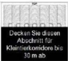
If you attach the detector so that adjoining sites are also included in the monitored area, turn the module and mask the beams horizontally or vertically, which fall outside the area to be monitored. To do this, use the stickers supplied on the smooth back of the lens. See the diagram below on the next page. When exchanging the lens, always make sure it is in the correct position to maintain the required area of detection (top of the Fresnel lens is marked with TOP). See Fig. 9.
| Multibeam – Optimal |  | 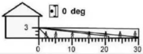 | |
| Height: | 3m | ||
| Range: | Maximum | ||
| Module Tilt: | 0° | ||
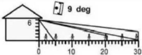
| Multibeam |  | 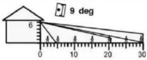 | |
| Height: | 6m | ||
| Range: | Maximum | ||
| Module Tilt: | 9° | ||
| Pet Immunity |  | 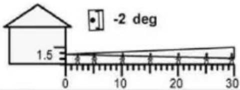 | |
| Height: | 1.5m | ||
| Range: | Maximum | ||
| Module Tilt: | -2° | ||

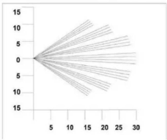
line
| x | y | |----|------| | 0 | 0 | | 5 | 5 | | 10 | 10 | | 15 | 15 | | 20 | 10 | | 25 | 5 | | 30 | 0 |Beam pattern set to maximum range.
Covering the top section reduces the range to 20 metres.

line
| x | y | |----|------| | 0 | 0.0 | | 2 | 1.5 | | 4 | 3.0 | | 6 | 4.5 | | 8 | 6.0 | | 10 | 7.5 | | 12 | 9.0 | | 14 | 10.5 |Beam pattern set to minimum range.
Covering the top section reduces the range to 6 metres.

natural_image
Diagram of a device interior with directional arrows indicating rotation or movement, labeled Fig. 9 (no text or symbols on the diagram itself)Programming
You can configure the detector in a number of ways. See the Programming table. The factory settings are shaded. Changes can be made. To restore the factory settings, switch off the detector's power supply. Then press and hold down the program button (Fig. 10) and reconnect the detector again to the power: either prior to installation with a suitable battery or with 12 V on site.

| Programming table | |||||
| Options | 1 | Range in metres | 10 | 20 | 30 |
| 2 | Pulse counter | 1 | 2 | ||
| 3 | LED | OFF | ON | ||
To change the settings: press the program button from Fig. 10 to get the options, i.e. 1x for the range, 2x for the pulse counter, 3x for the LED. Wait 4 seconds until the blue LED display goes out. The current setting appears in the display.
To change the setting for this option, press the button until you reach the required setting. The display lights up twice and the changes are saved. Each change made to the settings is transferred to the detector memory and remains there, even if the voltage cuts off.
EXAMPLE: To change the LED setting from off to on.
Press the program button three times and then release.
Wait until the display goes out.
The display flashes once.
Press the program button twice and then release.
The display flashes twice to indicate that the option has been saved and the detector returns to normal mode.
Setting options
PULSE COUNTER
The number of events which both sensors have to detect before an output is indicated.
LED DISPLAY
LED off – LED switched off
LED on – LED indicates a detection
Technical data
| Detection area | Programmable between 10 and 30 metres. |
| Cover | 10–70° detection angle, 30 m × 30 m maximum cover. |
| Adjustment | 180° panning + 90° tiltingCover for reducing the area (if required). |
| Fresnel lens | 28 zones per pyro pair that can be masked with shutters or special tape (supplied). |
| Customer-specific appearance | Double-shielded silicon quad element absorbs 50,000 lux white light |
| Outputs | Magnetically protected, quiet semi-conductor relay. |
| Output 1 NO | Volt free relay contact 24 V AC/DC at 50 mA with integrated 25R series resistance, NO, alarm duration 10 seconds |
| Output 2 NC | Volt free relay contact 24 V AC/DC at 50 mA with integrated 25R series resistance, NC, alarm duration 10 seconds |
| Connected load | 9 to 15 V DC. |
| Current | 8 mA (12 V nominal). |
| Pulse counter | 1–2 |
| Temperature compensation | Temperature-dependent, digital adjustment. |
| Control | Digital microprocessor – non-volatile memory. |
| Walk test | Output – test mode with LED display. |
| Operating temperature | -20 to +55°CUniformly coated electronics for improved stability. |
| Housing | Polyethylene HDPE |
| Protection class | IP 55. |
| Dimensions | 145 × 120 × 115 mm. |
| Weight | 750 g net, 880 g gross. |
| Installation height | Variable up to 6 m – optimum height at 3 m. |
| Cable < 200 m | For all 3 outputs (including tamper output) – 8-wire 7/0.2 mm. |
| Cable < 500 m | For all 3 outputs (including tamper output) – 8-wire 16/0.2 mm. |
The manufacturer reserves the right to make technical modifications at any time.
Introduction
natural_image
Simple line drawing of a balloon with a handle and arrow, no text or symbols presentFig. 3.2

natural_image
Diagram of a medical device with arrows indicating movement or force (no text or symbols)
natural_image
Diagram of a device with a curved panel and internal component, labeled Fig. 3.3 (no text or symbols on the diagram itself)
natural_image
Diagram of a device with cable and connector, labeled Fig. 2 (no text or symbols on the diagram itself)
natural_image
Exploded view diagram of an electrical component with screw and cable assembly (no text or labels)Fig. 8
line
| x | y | |----|------| | 0 | 0.0 | | 5 | 2.5 | | 10 | 5.0 | | 15 | 7.5 | | 20 | 10.0 | | 25 | 12.5 | | 30 | 15.0 |natural_image
Diagram of a device interior showing internal components and directional arrows, labeled Fig. 9 (no text or symbols on the diagram itself)Programmation
natural_image
Diagram of a device casing with labeled buttons and ports (no text or symbols)Afb. 8
line
| x | y | |----|------| | 0 | 0.0 | | 5 | 2.5 | | 10 | 5.0 | | 15 | 7.5 | | 20 | 10.0 | | 25 | 12.5 | | 30 | 15.0 |natural_image
Diagram of a device interior with directional arrows indicating rotation or movement, labeled 'Afb. 9' (no text or symbols on the diagram itself)Programmering
Fig. 8
natural_image
Pure electrical circuit lines without any symbols[Non-Text]
Sma dyr immunitet
Højde: 1.5m
line
| x | y | |----|------| | 0 | 0 | | 2 | 0 | | 4 | 0 | | 6 | 0 | | 8 | 0 | | 10 | 0 | | 12 | 0 | | 14 | 0 |natural_image
Diagram of a device interior showing internal components and directional arrows, labeled Fig. 9 (no text or symbols on the diagram itself)Programmering
natural_image
Diagram showing two abstract geometric shapes with crosshair markers and dashed lines, no text or symbols present.Fig. 1
Fig. 8
natural_image
Pure electrical circuit lines without any symbols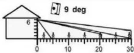
natural_image
Diagram of a device interior showing internal components and directional arrows, labeled Fig. 9 (no text or symbols on the diagram itself)Programmazione
LED off – LED spento
"ABUS Security-Center GmbH & Co. KG, Linker Kreuthweg 5, D-86444 Affing, hereby declares that the AZBW20000 complies with the basic requirements and other relevant terms of the EMC directive 2004/108/EC."
The declaration of conformity can be found at www.abus-sc.de


Brand : ABUS
Model : AZBW20000
Category : Motion detector