
20074 - Welding machine GUDE - Free user manual and instructions
Find the device manual for free 20074 GUDE in PDF.


| Product Type | Inverter welding machine |
| Brand | Güde |
| Model | 20074 |
| Dimensions (L x W x H) | 30 x 15 x 25 cm |
| Weight | 4.5 kg |
| Power supply | 230 V ~ 50 Hz |
| Power consumption | 3.2 kVA |
| Welding current (MMA) | 20 – 160 A |
| Open circuit voltage | 72 V |
| Duty cycle (at 40 °C) | 60% at 160 A, 100% at 100 A |
| Electrode diameter | 1.6 – 4.0 mm |
| Recommended weld thickness | 1 – 6 mm |
| Welding functions | MMA (stick electrode), TIG (with optional torch) |
| Additional features | Anti-stick, Hot Start, Arc Force |
| Thermal protection | Yes, automatic shutdown in case of overheating |
| Protection rating | IP21S |
| Insulation class | F |
| Maintenance and cleaning | Regularly dust the ventilation slots; clean the torch and electrode holder |
| Spare parts and repairability | Available from the manufacturer or authorized dealer; repair by a professional recommended |
| General information | User manual available for free download in PDF format |
Frequently Asked Questions - 20074 GUDE
User questions about 20074 GUDE
0 question about this device. Answer the ones you know or ask your own.
Ask a new question about this device
Download the instructions for your Welding machine in PDF format for free! Find your manual 20074 - GUDE and take your electronic device back in hand. On this page are published all the documents necessary for the use of your device. 20074 by GUDE.
USER MANUAL 20074 GUDE
natural_image
Close-up of a black and blue electric shaver with coiled cable, no visible text or symbols
ENGLISH Please read the instructions carefully before starting the machine.
English TECHNICAL DATA | SPECIFIED CONDITIONS OF USE | SAFETY INSTRUCTIONS | MAINTENANCE | GUARANTEE | EC-DECLARATION OF CONFORMITY ____ 16
Français CARACTÉRISTIQUES TECHNIQUES | UTILISATION CONFORME à LA DESTINATION | CONSIGNES DE SÉCURITÉ | ENTRETIEN | GARANTIE | DÉCLARATION DE CONFORMITÉ CE ____ 20
natural_image
Illustration of various electronic components including a cardboard box, a blue industrial machine, and mechanical parts (no text or symbols)
natural_image
Blue industrial battery housing with cooling fins and mounting bracket (no text or symbols visible)

natural_image
3D diagram of a mechanical component with two arrows pointing to features, no visible text or symbols
natural_image
Close-up of a mechanical component with two metallic rods and a white arrow pointing to a small black object on a surface (no text or symbols visible)

natural_image
Diagram of a mechanical component with two vertical supports and a horizontal bar, labeled with numbers 5 and 4 (no text or symbols on the diagram itself)DE Montage SI Montaža
GB Assembly HR Montaža
FR Montage BG Монтаж
IT Montaggio RO Montaj
NL Montage BA Montaža
CZ Montáž
SK Montáž
HU Szerelés


| 1 | DE Montage | SI Montaža |
| GB Assembly | HR Montaža | |
| FR Montage | BG Монтаж | |
| IT Montaggio | RO Montaj | |
| NL Montage | BA Montaža | |
| CZ Montáž | ||
| SK Montáž | ||
| HU Szerelés |

GB Starting-up the machine
FR mise en service
natural_image
Blue industrial gas cylinder with attached cart, labeled 'GAS' (no text or symbols on device body)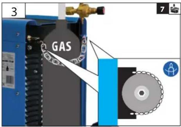

| 2 | DE InbetriebnahmeGB Starting-up the machineFR mise en serviceIT Messa in funzioneNL InbedrijfstellingCZ Uvedení do provozuSK Uvedenie do prevádzkyHU Üzembe helyezés | SI Uvedba v pogonHR Puštanje u radBG Пускане в действиеRO Punerea în funcțiuneBA Puštanje u rad |


natural_image
Blue industrial machine with wheels and open lid, no visible text or symbols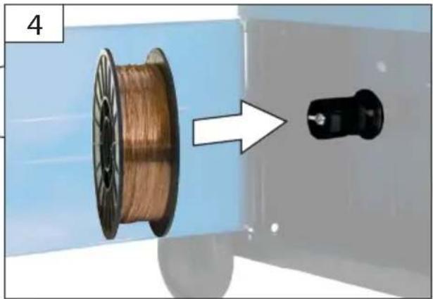
natural_image
Close-up of a copper wire spool being placed on a mechanical component, with an arrow indicating the process (no text or symbols visible) |
DE Inbetriebnahme
GB Starting-up the machine
FR mise en service


DE Betrieb
GB Operation
FR Fonctionnement
IT Esercizio
NL Gebruik
CZ Provoz
SK Prevádzka
HU Üzemeltetés
SI Delovanje
HR Rad
BG Работа
RO Functionare
Ba Rad


4
natural_image
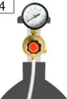
Close-up of a mechanical pressure gauge and valve component (no text or symbols visible)| MIG MaG | |||
| alAlu | FeSteel | Fe a2, a4Stainless Steel, Inox, Nirosta | |
| ArHe | Ar/CO_2 CO_2 | Ar/CO_2 Ar/CO_2/O_2 | |


natural_image
Close-up of a welding torch with a blue handle and red grip, emitting light (no text or symbols visible)
natural_image
Close-up of a black fuel nozzle with blue tip and red handle, emitting light trail (no text or symbols visible)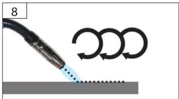

natural_image
Simple gray rectangle with a black horizontal line and a blue checkmark in the top-right corner (no text or symbols)
natural_image
Simple red 'X' mark on a black horizontal line against a gray background (no text or symbols)
3
GB Cleaning / Maintenance
FR Nettoyage / Entretien
natural_image
Close-up of a blue welding torch with a metallic connector and an arrow pointing to it (no text or symbols)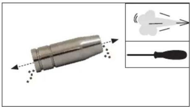
natural_image
Illustration of a mechanical component with motion arrows and two inset diagrams showing exhaust or impulse patterns (no text or symbols)
natural_image
Close-up of a blue welding torch emitting a brown pipe with directional arrows indicating motion (no text or symbols)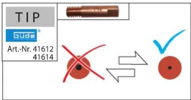
natural_image
Close-up of a blue electric plug connecting two metallic connectors with directional arrows indicating motion (no text or symbols)
natural_image
Close-up of a cable being inserted into a mechanical component, showing internal components and a dashed line indicating assembly (no text or symbols)Technische Daten
Schweißgerät 172/6W
Artikel-Nr. 20074
Service connection....230 V \~ 50 Hz
Rated input voltage (AC Voltage) U 230 V
Protection 16 A
Maximum rated input current I_max 27 A
Maximum effective input current I_eff 9,7 A
Idle voltage U_0 40 V
Regulated section.... 25-135 A
Switch-on time X * .... 10%....20%....30%....60%....100%....100%
Welding current I, 145 A, 110 A, 77 A, 54 A, 42 A, 25 A
Operating voltage U_2 .....20,75 V.....19 V.....17,8 V.....16,7 V.....16,1 V.....15,25 V
Wire thickness....0,6 - 1,0 mm
Material thickness....1 - 8 mm
Weight....34 kg
Dimensions.... 650 x 285 x 460 mm
Degree of protection....IP 21S
Insulation class....H
* Actual working time and total working time ratio.
Switch-on time determined at 40°C using simulation


Read and understand the operating instructions before using the appliance. Abide by all
the safety measures stated in the service manual. Act responsibly toward third parties.
In case of any doubts about connection and operation refer please to our customer center
Specified Conditions Of Use
Welder in protective atmosphere for thermal connection of ferrous metals by melting edges and including mixture
Do not use this product in any other way as stated for normal use. Not observing general regulations in force and instructions from this manual does not make the manufacturer liable for damages.
Safety instructions
WARNING! Electric shock! There is a risk of an injury caused by electric shock!
Operation is only allowed with a safety switch against stray current (RCD max. stray current of 30mA).
IP21 protection degree of the welder. The welder must not be exposed to rain and moisture when being operated or stored.
Check the voltage. Technical data given on the type label must correspond with electric network voltage.
Insert the plug of the electrical cable in a socket of suitable shape, voltage and frequency complying with current regulations.
Use extension cables with a maximum length of 5 meters and with a cable cross-section of not less than 1.5 mm ^2 . Use of extension cables of different length and cross-section and also of adapters and multiple sockets should be avoided.
Check the cable and/or socket for damages before the appliance putting into operation.
Defective cable or plug may cause electric shock.
Do not pull the service cable to pull the plug out of socket.
Do not expose yourself or other persons without protection to electric arc or hot metal. Spraying welding pearls may cause burns.
A suitable welding shield, protective clothes and protective gloves to be worn at all times.
Long-term inhalation of welding gases may be harmful to your health.
Work with an exhaust system or in well ventilated spaces. Avoid direct inhalation of gases.
Contact with the hose bundle nozzle and the material being processed may cause burns. Special welding gloves to be worn at all times.
Let the hose bundle nozzle and the material being processed cool down after being operated.
Long-term working with the appliance may damage hearing. Hearing protection to be used at all times.
Welder may only be used on a flat surface and with a properly secured gas bottle.
Make sure the welding smoke is exhausted or the place of welding ventilated well.
Hot slag and sparks may cause fire or explosion. Never use the appliance in a flammable environment.
Wood, sawdust, "varnishes", petrol, kerosine, natural gas, acetylene, propane and similar flammable materials must be removed from the place of work and the surrounding area or protected against sparks flying away.
To extinguish fire, a suitable fire extinguisher must be made ready nearby.
No welding or cutting on closed vessels and pipes.
No welding or cutting on vessels and pipes if they are open, containing materials able to explode due to heat or moisture or able to cause other dangerous reactions.
Never use the welder to defrost frozen pipes.
The gas bottle must necessarily be secured against falling. The welder must never be lifted together with the gas bottle. Special regulations apply to the transport of gas bottles.
Handling of gas bottles.
Make sure the gas bottles are used and stored in rooms with sufficient air inlet and outlet.
A leaking gas bottle may reduce the share of oxygen in the inhaled air and therefore represent a risk of suffocation.
Before use, make sure the gas bottle contains gas designed for the work being done.
Gas bottles must always be safely fixed in a vertical position on a wall support or on a specially manufactured gas bottle cart.
The bottle with shielding gas and the fixed adjustment gas current equipment must not be moved. The gas bottle valve must be closed during transport.
Close the gas bottle valve after use.
Symbols


Caution! Read the Operating Instructions!

Wear personal protective equipment.

Welding mask to be used!

Special welding gloves to be worn at all times.

Wear safety cut through resistant shoes with safety sole and steel toe!

Protective apron to be used

Before carrying out any work on the machine, disconnect the plug from the socket.

Pressure bottle to be secured by chain


Warning against dangerous voltage


Risk of explosion


Warning against toxic fumes!

Protect against humidity Never expose tool to rain.

Keep distance of persons Observe to keep out of dangerous zone

Single-phase transformer with rectifier

MIG (welding, metal-inert-gas) MAG (welding, metal-active-gas)

Suitable for welding with an increased electric risk.

Single-phase alternating current with rated frequency of 50 Hz

Any damaged or disposed electric or electronic devices must be delivered to appropriate collection centres.

Protect against humidity

This side up
Requirements for operating staff
The operating staff must carefully read the Operating Instructions before using the appliance.
Qualification: Apart from the detailed instructions by a professional, no special qualification is necessary for appliance using.
Minimum age: Persons over 18 years of age can only work on the appliance. An exception includes youngsters trained in order to reach knowledge under supervision of the trainer during occupational education.
Training: Using the appliance only requires corresponding training by a professional or the Operating Instructions. No special training is necessary.
Emergency procedure
Conduct a first-aid procedure adequate to the injury and summon qualified medical attendance as quickly as possible. Protect the injured person from further harm and calm them down. For the sake of eventual accident, in accordance with DIN 13164, a workplace has to be fitted with a first-aid kit. It is essential to replace any used material in the first-aid kit immediately after it has been used.
If you seek help, state the following pieces of information:
- Accident site
- Accident type
- Number of injured persons
- Injury type(s)
Maintenance

Before carrying out any work on the machine, connect the plug from the socket.
If the device is defective, the repair has to be made exclusively by the customer service.
Use only original accessories and original spare parts.
Never clean the machine and its components with solvents, flammable or toxic liquids. Us only a damp cloth making.
Use a soft brush to remove the deposited dust from the ventilation hole and moving parts after each use.
All moving metal parts, e.g. wheels and the side cover, to be regularly lubricated with oil.
Only a regularly maintained and treated appliance can serve as a satisfactory aid. Insufficient maintenance and care can lead to unforeseen accidents and injuries.
If necessary, a list of spare parts can be found at www.guede.com.
Guarantee
Warranty period of 12 months applies to commercial use and 24 months applies to private use and commences on the day of purchase of the device.
The guarantee solely covers inadequacies caused by material defect or manufacturing defect. Original payment voucher with the sales date needs to be submitted for any claim in the guarantee period.
The guarantee does not cover any unauthorised use such as appliance overloading, use of violence, damage as a result of any unauthorised interference or caused by foreign items. Failing to follow the operating and assembly instructions and common wear are also not included in the guarantee.
Service
Do you have any technical questions? Any claim? Do you need any spare parts or operating instructions? We will quickly help you and without needles bureaucracy at our web pages at www.guede.com in the Servicing part. Please help us be able to help you. In order to identify your device in case of claim we need the serial No., product No. and year of production. All this data can be found on the type label. Please enter it here for future reference:
Serial No.:
Art. No:
Prior to every use, visually check the machine to rule out any defects, in particular on the power cable and the plug.
Year of production:
The machine must not be used under any circumstances if the machine or the safety devices are damaged.
Failure removal
| Failures Causes Removal | ||
| Wire not feeding despite wire feed pulley turning. | Dirty current nozzle Clean | |
| Coil carrier clutch set too tight. Loosen | ||
| Damaged hose bundle Check the wire guide housing | ||
| Too low clamping pressure of the wire feed pulley | Increase the clamping pressure | |
| Interrupted or disruptive wire supply | Damaged current nozzle Replace | |
| Burnt current nozzle Replace | ||
| Dirty driving gear nozzle Clean | ||
| Cut on worn driving gear Replace | ||
| Electric arc turned off Poor contact between earth pliers and the respective part | Tighten the pliers and check themRemove paint and rust | |
| Porous welded joint Wrong distance of inclination of the hose bundle | Distance between the hose bundle and the respective part must be 5-10 mm. Inclination must not be lower than 60 with respect to the part. | |
| Welder suddenly stops working after longer operation | Welder has overheated due to too long use and the thermal protection has activated | Let the welder cool down |
Doba zapnutí X * .....10% .....20% .....30% .....60% .....100% .....100%
Švařovací proud I, 145 A. 110 A. 77 A. 54 A. 42 A. 25 A
Pracovní napětí U _7 ......20,75 V......19 V......17,8 V......16,7 V......16,1 V......15,25 V
Čas zapnutia X * 10% 20% 30% 60% 100% 100%
Zvárací prúd I, 145 A....110 A....77 A....54 A....42 A....25 A
Pracovné napätie U, 20,75 V 19 V 17,8 V 16,7 V 16,1 V 15,25 V
Hrúbka drôtu....0,6 - 1,0 mm
- Hrúbka materiálu....1 - 8 mm
Hmotnost.... 34 kg
Rozmer 650 x 285 x 460 mm


Brand : GUDE
Model : 20074
Category : Welding machine