
Trio - Multitools DREMEL - Free user manual and instructions
Find the device manual for free Trio DREMEL in PDF.


| Product type | Rotary multifunction tool |
| Brand | DREMEL |
| Model | Trio |
| Supply voltage | 230 V, 50 Hz |
| Power | 135 W |
| No-load speed | 8,000 – 32,000 rpm |
| Dimensions (L x W x H) | 28 x 6 x 6 cm |
| Net weight | 0.85 kg |
| Housing material | Reinforced plastic |
| Motor type | Brushed |
| Power supply | Corded |
| Cable length | 3 m |
| Noise level | 85 dB(A) |
| Vibration | < 2.5 m/s² |
| Main functions | Cutting, carving, engraving, polishing, drilling, cleaning |
| Included accessories | 6 bits, collet, cutting guide, brush, tightening wrench |
| Maintenance | Clean after each use, lubricate moving parts |
| Cleaning | Dry or slightly damp cloth, avoid harsh solvents |
| Safety | Wear safety goggles and dust mask, unplug before changing accessories |
| Warranty | 2 years |
| Spare parts available | Yes, on DREMEL website |
Frequently Asked Questions - Trio DREMEL
User questions about Trio DREMEL
0 question about this device. Answer the ones you know or ask your own.
Ask a new question about this device
Download the instructions for your Multitools in PDF format for free! Find your manual Trio - DREMEL and take your electronic device back in hand. On this page are published all the documents necessary for the use of your device. Trio by DREMEL.
USER MANUAL Trio DREMEL
natural_image
Illustration of a Dremel TRIO™ electric tool with no visible text or symbols on the device bodyGB Original instructions 9
D Übersetzung der originalbedienungsanleitung 14
F Traduction de la notice originale 20
Traduzione delle istruzioni originali 25
NL Vertaling van de originele gebruiksaanwijzing 31
DK Oversættelse af betjeningsvejledning 38
S Översättning av originalinstruktioner 43
N Oversettelse av originalinstruksjonene 48
FIN Käännös alkuperäisistä ohjeista 53
EST Algsete juhiste tõlge 58
LT Originaaljuhendi tõlge 63
LV Sākotnējo norādījumu tulkojums 69
AR ٧٥ تيلىصألا تاميلعتلا قمجر


natural_image
Line drawing of a vacuum cleaner device with no visible text or symbols


9
 |  |  |  |  |  |  |  |
 TR407 TR407 | 200002000010000-1500010000-1200012000-17000-- | ||||||
| TR408200002000010000-1500010000-1200012000-17000-- | |||||||
| TR432200002000010000-1500010000-1200012000-17000-- | |||||||
 TR612 TR612 | 2000018000-20000---- | ||||||
 TR618 TR618 | 2000018000-20000---- | ||||||
 TR654 TR654 | 2000018000-20000---- | ||||||
 TR560 TR560 | 15000-2000015000-2000010000-2000015000-2000015000-20000-- | ||||||
 TR562 TR562 | ----15000-2000015000-20000 | ||||||
 TR563 TR563 | 15000-2000015000-2000015000-2000015000-20000-- | ||||||

flowchart
graph TD
    A["Stage A"] --> B["Stage B"]
    B --> C["Stage C"]
    C --> D["Stage D"]
    D --> A
    style A fill:#f9f,stroke:#333
    style B fill:#ccf,stroke:#333
    style C fill:#cfc,stroke:#333
    style D fill:#fcc,stroke:#333

natural_image
Technical line drawing of a mechanical device with a tool and motion arrow (no text or symbols)
natural_image
Technical line drawing of a mechanical assembly with mounting base and central component (no text or symbols)

natural_image
Line drawing of a sewing machine with a base mount and handle, no text or symbols presentGB
CE DECLARATION OF CONFORMITY We declare under our sole responsibility that this product is in conformity with the following standards or standardised documents: EN 60 745, EN 55 014, in accordance with the provisions of the directives 2006/95/EC, 2004/108/EC, 2006/42/EC.
NOISE/VIBRATION Measured in accordance with EN 60 745 the sound pressure level of this tool is 71.0 dB(A) and the sound power level 82.0 dB(A) (standard deviation: 3 dB), and the vibration * m/s 2 (hand-arm method).
NOTE: The declared vibration total value has been measured in accordance with a standard test method and may be used for comparing one tool with another. It may also be used in a preliminary assessment of exposure.

WARNING
The vibration emission during actual use of the power tool can differ from the declared total value depending on the ways in which you use the tool.
Make an estimation of the exposure in the actual conditions of use and identify the safety measures for personal protection accordingly (taking account of all parts of the operating cycle such as the times when the tool is switched off and when it is running idle in addition to the trigger time).
Technical file at: SKIL Europe BV (PT-SEU/PJE), 4825 BD Breda, NL.
D
READ THESE INSTRUCTIONS

USE A DUST MASK, EAR AND EYE PROTECTION
GENERAL POWER TOOL SAFETY WARNINGS

WARNING
READ ALL SAFETY WARNINGS AND ALL INSTRUCTIONS.
Failure to follow the warnings and instructions may result in electric shock, fire and/or serious injury.
Save all warnings and instructions for future reference.
The term “power tool” in the warnings refers to your mains-operated (corded) power tool or battery-operated (cordless) power tool.
WORK AREA SAFETY
a. Keep work area clean and well lit. Cluttered and dark areas invite accidents.
b. Do not operate power tools in explosive atmospheres, such as in the presence of flammable liquids, gases or dust. Power tools create sparks which may ignite the dust or fumes.
c. Keep children and bystanders away while operating a power tool. Distractions can cause you to lose control.
ELECTRICAL SAFETY
a. Power tool plug must match the outlet. Never modify the plug in any way. Do not use any adapter plugs with earthed (grounded) power tools. Unmodified plugs and matching outlets will reduce risk of electric shock.
b. Avoid body contact with earthed or grounded surfaces such as pipes, radiators, ranges and refrigerators. There is an increased risk of electric shock if your body is earthed or grounded.
c. Do not expose power tools to rain or wet conditions. Water entering a power tool will increase the risk of electric shock.
d. Do not abuse the cord. Never use the cord for carrying, pulling or unplugging the power tool. Keep cord away from heat, oil, sharp edges or moving parts. Damaged or entangled cords increase the risk of electric shock.
e. When operating a power tool outdoors, use an extension cord suitable for outdoor use. Use of a cord suitable for outdoor use reduces the risk of electric shock.
f. If operating a power tool in a damp location is unavoidable, use an earth leakage circuit breaker (ELCB). Use of an earth leakage circuit breaker reduces the risk of electric shock.
PERSONAL SAFETY
a. Stay alert, watch what you are doing and use common sense when operating a power tool. Do not use a power tool while you are tired or under the influence of drugs, alcohol or medication. A moment of inattention while operating power tools may result in serious personal injury.
b. Use personal protective equipment. Always wear eye and hearing protection. Protective equipment such as dust mask, non-skid safety shoes, hard hat, or hearing protection used for appropriate conditions will reduce personal injuries.
c. Prevent unintentional starting. Ensure the switch is in the off-position before connecting to power source and/or battery pack, picking up or carrying the tool. Carrying power tools with your finger on the switch or energising power tools that have the switch on invites accidents.
d. Remove any adjusting key or wrench before turning the power tool on. A wrench or a key left attached to a rotating part of the power tool may result in personal injury.
e. Do not overreach. Keep proper footing and balance at all times. This enables better control of the power tool in unexpected situations.
f. Dress properly. Do not wear loose clothing or jewellery. Keep your hair, clothing and gloves away from moving parts. Loose clothes, jewellery or long hair can be caught in moving parts.
g. If devices are provided for the connection of dust extraction and collection facilities, ensure these are connected and properly used. Use of these devices can reduce dust related hazards.
POWER TOOL USE AND CARE
a. Do not force the power tool. Use the correct power tool for your application. The correct power tool will do the job better and safer at the rate for which it was designed.
b. Do not use the power tool if the switch does not turn it on and off. Any power tool that cannot be controlled with the switch is dangerous and must be repaired.
c. Disconnect the plug from the power source and/or the battery pack from the power tool before making any adjustments, changing accessories, or storing power tools. Such preventive safety measures reduce the risk of starting the power tool accidentally.
d. Store idle power tools out of the reach of children and do not allow persons unfamiliar with the power tool or these instructions to operate the power tool. Power tools are dangerous in the hands of untrained users.
e. Maintain power tools. Check for misalignment or binding of moving parts, breakage of parts and any other condition that may affect the power tools operation. If damaged, have the power tool repaired before use. Many accidents are caused by poorly maintained power tools.
f. Keep cutting tools sharp and clean. Properly maintained cutting tools with sharp cutting edges are less likely to bind and are easier to control.
g. Use the power tool, accessories and tool bits etc., in accordance with these instructions, taking into account the working conditions and the work to be performed. Use of the power tool for operations different from those intended could result in a hazardous situation.
SERVICE
a. Have your power tool serviced by the manufacturer or its authorised agent in order to avoid a safety hazard using only identical replacement parts. This will ensure that the safety of the power tool is maintained.
SAFETY INSTRUCTIONS FOR ALL OPERATIONS
SAFETY WARNINGS COMMON FOR GRINDING, SANDING, WIRE BRUSHING, POLISHING OR ABRASIVE CUTTING-OFF OPERATIONS
a. This power tool is intended to function as a grinder or sander. Read all safety warnings, instructions, illustrations and specifications provided with this power tool. Failure to follow all instructions listed below may result in electric shock, fire and/or serious injury.
b. Operations such as wire brushing, polishing or cutting-off are not recommended to be performed with this power tool. Operations for which the power tool was not designed may create a hazard and cause personal injury.
c. Do not use accessories which are not specifically designed and recommended by the tool manufacturer. Just because the accessory can be attached to your power tool, it does not assure safe operation.
d. The rated speed of the accessory must be at least equal to the maximum speed marked on the power tool. Accessories running faster than their rated speed can break and fly apart.
e. The outside diameter and the thickness of your accessory must be within the capacity rating of your power tool. Incorrectly sized accessories cannot be adequately guarded or controlled.
f. The arbour size of wheels, flanges, backing pads or any other accessory must properly fit the spindle of the power tool. Accessories with arbour holes that do not match the mounting hardware of the power tool will run out of balance, vibrate excessively and may cause loss of control.
g. Do not use a damaged accessory. Before each use inspect the accessory such as abrasive wheels for chips and cracks, backing pad for cracks, tear or excess wear, wire brush for loose or cracked wires. If power tool or accessory is dropped, inspect for damage or install an undamaged accessory. After inspecting and installing anaccessory, position yourself and bystanders away from the plane of the rotating accessory and run the power tool at maximum no-load speed for one minute. Damaged accessories will normally break apart during this test time.
h. Wear personal protective equipment. Depending on application, use face shield, safety goggles or safety glasses. As appropriate, wear dust mask, hearing
protectors, gloves and workshop apron capable of stopping small abrasive or work piece fragments. The eye protection must be capable of stopping flying debris generated by various operations. The dust mask or respirator must be capable of filtrating particles generated by your operation. Prolonged exposure to high intensity noise may cause hearing loss.
i. Keep bystanders a safe distance away from work area. Anyone entering the work area must wear personal protective equipment. Fragments of work piece or of a broken accessory may fly away and cause injury beyond immediate area of operation.
j. Hold power tool by insulated gripping surfaces only, when performing an operation where the cutting accessory may contact hidden wiring or its own cord.
A cutting accessory contacting a "live" wire may make exposed metal parts of the power tool "live" and shock the operator.
k. Position the cord clear of the spinning accessory. If you lose control, the cord may be cut or snagged and your hand or arm may be pulled into the spinning accessory.
I. Never lay the power tool down until the accessory has come to a complete stop. The spinning accessory may grab the surface and pull the power tool out of your control.
m. Do not run the power tool while carrying it at your side. Accidental contact with the spinning accessory could snag your clothing, pulling the accessory into your body.
n. Regularly clean the power tool's air vents. The motor's fan will draw the dust inside the housing and excessive accumulation of powdered metal may cause electrical hazards.
o. Do not operate the power tool near flammable materials. Sparks could ignite these materials.
p. Do not use accessories that require liquid coolants. Using water or other liquid coolants may result in electrocution or shock.
KICKBACK AND RELATED WARNINGS
Kickback is a sudden reaction to a pinched or snagged rotating wheel, backing pad, brush or any other accessory. Pinching or snagging causes rapid stalling of the rotating accessory which in turn causes the uncontrolled power tool to be forced in the direction opposite of the accessory's rotation at the point of the binding. For example, if an abrasive wheel is snagged or pinched by the work piece, the edge of the wheel that is entering into the pinch point can dig into the surface of the material causing the wheel to climb out or kick out. The wheel may either jump toward or away from the operator, depending on direction of the wheel's movement at the point of pinching. Abrasive wheels may also break under these conditions. Kickback is the result of power tool misuse and/or incorrect operating procedures or conditions and can be avoided by taking proper precautions as given below.
a. Maintain a firm grip on the power tool and position your body and arm to allow you to resist kickback forces. Always use auxiliary handle, if provided, for maximum control over kickback or torque reaction during start-up. The operator can control torque reactions or kickback forces, if proper precautions are taken.
b. Never place your hand near the rotating accessory.
Accessory may kickback over your hand.
c. Do not position your body in the area where power tool will move if kickback occurs. Kickback will propel the tool in direction opposite to the wheel's movement at the point of snagging.
d. Use special care when working corners, sharp edges etc. Avoid bouncing and snagging the accessory. Corners, sharp edges or bouncing have a tendency to snag the rotating accessory and cause loss of control or kickback.
e. Do not attach a saw chain woodcarving blade or toothed saw blade. Such blades create frequent kickback and loss of control.
SAFETY WARNINGS SPECIFIC FOR GRINDING AND ABRASIVE CUTTING-OFF OPERATIONS
a. Use only wheel types that are recommended for your power tool and the specific guard designed for the selected wheel. Wheels for which the power tool was not designed cannot be adequately guarded and are unsafe.
b. Wheels must be used only for recommended applications. For example: do not grind with the side of cut-off wheel. Abrasive cut-off wheels are intended for peripheral grinding, side forces applied to these wheels may cause them to shatter.
c. Always use undamaged wheel flanges that are of correct size and shape for your selected wheel. Proper wheel flanges support the wheel thus reducing the possibility of wheel breakage. Flanges for cut-off wheels may be different from grinding wheel flanges.
d. Do not use worn down wheels from larger power tools.
Wheel intended for larger power tool is not suitable for the higher speed of a smaller tool and may burst.
SAFETY WARNINGS SPECIFIC FOR SANDING OPERATIONS
a. Do not use excessively oversized sanding disc paper. Follow recommendations, when selecting sanding paper. Larger sanding paper extending beyond the sanding pad presents a laceration hazard and may cause snagging, tearing of the disc or kickback.

WARNING
Do not work with materials containing asbestos (asbestos is considered
carcinogenic).

WARNING
Take protective measures when during work dust can develop that is harmful
to one's health, combustible or explosive (some dusts are considered carcinogenic); wear a dust mask and work with dust/ chip extraction when connectable.
ENVIRONMENT
DISPOSAL
The machine, accessories and packaging should be sorted for environmental-friendly recycling.
ONLY FOR EUROPEAN COUNTRIES

Do not dispose of power tools into household waste! According to the European Guideline 2002/96/EC for Waste Electrical and Electronic Equipment and its implementation into national right, power tools that are no longer usable must be collected separately and disposed of in an environmentally correct manner.
SPECIFICATIONS
GENERAL SPECIFICATIONS
Rated power 200 W
Voltage rating ..... 230-240V 50-60 Hz
Collet capacity 4,8 mm
No load speed (n d ) . . . . . . . . 10000-20000/min
Class II construction .....
EXTENSION CORDS
Use completely unrolled and safe extension cords with a capacity of 5 Amps.
ASSEMBLY
ALWAYS TURN OFF THE TOOL BEFORE CHANGING ACCESSORIES, CHANGING COLLETS, OR SERVICING THE TOOL.
GENERAL
PICTURE 1
A. Articulation Button
B. "Lock-On" Button
C. Variable Speed Dial
D. Cord
E. Trigger "On-Off" Switch
F. Adjustment Thumb Screw
G. Dust Port
H. Dust Port Adapter
I. Base Plate
J. Collet
K. Collet Nut
L. Shaft Lock Button
M. Ventilation Openings
N. Wrench
0. Straight edge/circle guide
P. Base plate thumb screw
GETTING STARTED
The Dremel Trio Tool is intended for cutting wood, plastic, thin sheet metal, drywall, fiberboard, and wall tile using the applicable tools and accessories recommended by Dremel.
This tool also sands using a variety of sanding drums and routes using 4.8mm shank router bits. Make certain that the collet nut is securely tightened before turning the tool on.
USE
ARTICULATION BUTTON
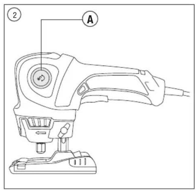
Your tool features a 2 position articulating head. To adjust, depress articulation button and move head to desired position (Fig. 2 or 3).
The articulation position is recommended for standard operations on a flat surface while in the 90° position (Fig. 2).

WARNING
Make sure articulation button clicks back out to lock the handle before
turning the tool on.

WARNING
Make sure the pivoting handle is securely locked in the desired position.
Operation when not secured properly may result in unexpected movement of the pivoting handle and could cause injury.

WARNING
Clamp the work piece in case it does not remain stationary from its own
weight.
DUST EXTRACTION
Your tool is equipped with a dust port (G) for dust extraction. To use this feature, insert dust port adapter (H) into dust port, attach vacuum cleaner into the adapter (Fig. 4).
DEPTH ADJUSTMENT
Loosen the depth adjustment thumb screw (F) (counter-clockwise) to change the depth of cut. Slide the base plate to the desired depth of cut (about 3.2mm greater than material thickness when cutting completely through something) and re-tighten the thumb screw (clockwise) (Fig. 5).
The maximum recommended depth of cut is 13mm of wood.
When using sanding drums and router bits it is recommended to make less aggressive more frequent passes through the material to extend the tool and accessory life.
TRIGGER "ON-OFF" SWITCH
To turn tool "ON", squeeze the trigger switch. To turn the tool "OFF", release the trigger switch which is spring loaded and will return to "OFF" position automatically (Fig. 6).
"LOCK-ON" BUTTON
The "Lock-ON" button, located in the handle of your tool allows for continuous operation without holding the trigger (Fig. 6).
- TO LOCK TRIGGER "ON": squeeze trigger, depress "Lock-ON" button and release trigger.
- TO UNLOCK THE TRIGGER: squeeze trigger and release it without depressing the "Lock-ON" button.
OVER CURRENT PROTECTION
Your tool is equipped with over current protection that will slow the motor automatically when overstressed. When this occurs you should reduce cutting pressure, rate of cut. The tool will increase speed again for maximum cutting performance.
VARIABLE SPEED DIAL
Your tool is equipped with a variable speed dial. The speed may be adjusted during operation by presetting the dial on or between any one of the settings (Fig. 7).
INSERTING BITS (Fig 8)
- Depress and hold the shaft-lock button (L) in and rotate the collet nut (K) and shaft until the shaft-lock engages and holds the shaft.
- Use the standard equipment wrench (N) to loosen nut (counter-clockwise).
- Remove the old bit insert the new bit as far in as possible.
- Re-engage the shaft-lock and tighten the nut (clockwise) by hand and then with the wrench until bit is held securely.
NOTE: Be sure to read the instructions supplied with your Dremel accessory for further information on its use.
NOTE: Use only Dremel TRIO, ∅4.8 mm shank accessories (Fig 9).
SPEED SETTINGS
* Speed for light cuts; Caution - burning on deep grooves.
* Depending on cutting direction relative to grain.
- For maximum control use a slow feed rate of cut.
- For maximum control place a second hand on the front of the tool or on the rear of the foot.
- For straightest possible cut use straight edge guide or fence.
- When using a fence, position it on the left side of the foot.
- When using a straight edge guide, position it on the right side of tool.
- When cutting most materials steer the tool in a clock-wise direction. Exception: when tracing an outlet steer counter clock-wise, an exception to this rule is when cutting around an outlet box.
SETTINGS FOR APPROXIMATE REVOLUTIONS (Fig. 9)
Switch Setting Speed Range
2 10000-12000 RPM
4 12000-14000 RPM
6 14000-16000 RPM
8 16000-18000 RPM
10 18000-20000 RPM
PROPER GUIDING (Fig. 10)
- Keep in mind that router bit turns clockwise
- Guide tool so that bit turns into the work piece, not away from it.
MAKE A FEW PRACTICE CUTS
After installing the bit into the tool and adjusting your depth guide, you should make a few practice cuts with the tool before attempting an actual job. A few exercises will give you the necessary practice to make clean, professional cuts.
Step 1: Make certain that the collet nut is securely tightened before turning the tool on.
Step 2: Hold the tool firmly and turn the tool ON to your desired speed.
Step 3: While holding the tool firmly, insert the bit into the material at a 45° angle, or 15° for tile (Fig. 11).
Step 4: Slowly plunge the bit to a 90° angle to begin the cut (Fig. 12). The base guide should be flush to the material surface. For all materials except when cutting around outlet boxes in drywall, steer the tool in a clockwise direction with slow, steady pressure to make the cut.
Step 5: After completing your cut, turn off the tool and carefully remove it from the material. Do not attempt to use this tool to make cut-outs around any fixture or opening which has live electrical wires, or any wall which may have live electrical wiring behind it, as the bit could conduct current to the tool, creating an electrocution hazard for the operator. Shut off breakers or remove fuses to disconnect the circuit. Always hold the tool by its thermoplastic housing, and always wear eye protection when operating the tool.
NOTE: Because of the rotating cutting action of the bit, there will be a slight pull when cutting. The slower you cut the more control you have. Excessive pressure or fast cutting will cause excessive heat and may shorten the life of the bit.
NOTE: When cutting on a vertical surface, avoid ending your cut at the bottom of the hole. If possible, start and end your cut at the top so the scrap part will not drop onto the rotating bit. Turn the tool off and remove it from the material.
USING THE STRAIGHT EDGE/CIRCLE GUIDE
STRAIGHT EDGE
The straight edge guide (optional) is used for cuts parallel to the edge of the work, and can be used from either side of the base plate for cutting on the left or right side of the material.
- Unscrew the base plate thumbscrew; slide the sliding rod of the straight edge guide through the two notches on the bottom side of the base plate.
- Position the tool to the desired length from the edge of your material. Tighten the thumbscrew (P) to secure the straight edge guide to the base plate (Fig. 13).
CUTTING LARGE DIAMETER CIRCLES (10 CM DIAMETER)
- Draw the circle on the work piece and mark the centre of the circle. Drill a centre hole with the tracer. Make sure the edge guide is facing UP (Fig. 14).
- Using the tool, plunge cut a pilot hole on the edge of the circle, turn tool off and disconnect the plug from power source.
a. To make a hole – cut from inside edge of the circle
b. To make wheels or discs – cut from the outside edge of the circle
- Attach straight edge guide to base plate, properly position base onto straight edge guide to give the desired circle diameter and lock down by tightening base plate thumbscrew.
- Insert plug into power source, hold the tool firmly, turn tool on and slowly push the tool forward.
MAINTENANCE
Preventative maintenance performed by unauthorised personnel may result in misplacing of internal wires and components which could cause serious hazard. We recommend that all tool service be performed by a Dremel Service Facility. To avoid injury from unexpected starting or electrical shock, always turn off power tool before performing service or cleaning.
CLEANING
WARNING
TO AVOID ACCIDENTS, ALWAYS DISCONNECT THE TOOL AND/OR CHARGER
FROM THE POWER SUPPLY BEFORE CLEANING. The tool can be cleaned most effectively with compressed dry air. Always wear safety goggles when cleaning tools with compressed air.
Ventilation openings and switch levers must be kept clean and free of foreign matter. Do not attempt to clean the tool by inserting pointed objects through an opening.
WARNING
CERTAIN CLEANING AGENTS AND SOLVENTS DAMAGE PLASTIC PARTS.
Some of these are: gasoline, carbon tetrachloride, chlorinated cleaning solvents, ammonia and household detergents that contain ammonia.
SERVICE AND WARRANTY
WARNING
NO USER SERVICEABLE PARTS INSIDE. Preventive maintenance performed by
unauthorised personnel may result in incorrect connection of internal wiring and components which could cause serious hazard. We recommend that all tool service be performed by a Dremel Service Centre. SERVICEMEN: Disconnect the tool and/or charger from the power source before servicing.
This DREMEL product is guaranteed in accordance with statutory/country-specific regulations; damage due to normal wear and tear, overload or improper handling is excluded from the warranty.
In case of a complaint, send the undismantled tool or charger and proof of purchase to your dealer.
CONTACT DREMEL
For more information on the Dremel product range, support and hotline, go to www.dremel.com.
Dremel Europe, P.O. Box 3267, 4800 DG Breda, The Netherlands

LISEZ CES INSTRUCTIONS

UTILISEZ UN MASQUE ANTI6POUSSIÈRE,
AINSI QUE DES PROTECTIONS AUDITIVES ET
OCULAIRES
AVERTISSEMENTS DE SÉCURITÉ GÉNÉRAUX CONCERNANT LES OUTILS ÉLECTROPORTATIFS

ATTENTION
LIRE L'ENSEMBLE DES CONSIGNES ET
AVERTISSEMENTS DE SÉCURITÉ.
GACHETTE "MARCHE-ARRÊT"
SOLO PER I PAESI EUROPEI

LEES ALLE VEILIGHEIDS- WAARSCHUWINGEN EN ALLE
INSTRUCTIES.
SIKKERHET FOR ARBEIDSOMRÅDET
HASTIGHETSINNSTILLINGER
YLEISET TEKNISET TIEDOT
Nimellisteho 200 W
Jännitearvot 230-240 V, 50-60 Hz
TAISNAS MALAS/APLA VADOTNES LIETOŠANA
TAISNA MALA
Dremel Europe The Netherlands


- GB
- WARNING
- D
- GENERAL POWER TOOL SAFETY WARNINGS
- WORK AREA SAFETY
- ELECTRICAL SAFETY
- PERSONAL SAFETY
- POWER TOOL USE AND CARE
- SERVICE
- SAFETY INSTRUCTIONS FOR ALL OPERATIONS
- SAFETY WARNINGS COMMON FOR GRINDING, SANDING, WIRE BRUSHING, POLISHING OR ABRASIVE CUTTING-OFF OPERATIONS
- KICKBACK AND RELATED WARNINGS
- SAFETY WARNINGS SPECIFIC FOR GRINDING AND ABRASIVE CUTTING-OFF OPERATIONS
- SAFETY WARNINGS SPECIFIC FOR SANDING OPERATIONS
- ENVIRONMENT
- DISPOSAL
- ONLY FOR EUROPEAN COUNTRIES
- SPECIFICATIONS
- GENERAL SPECIFICATIONS
- EXTENSION CORDS
- ASSEMBLY
- GENERAL
- PICTURE 1
- GETTING STARTED
- USE
- ARTICULATION BUTTON
- DUST EXTRACTION
- DEPTH ADJUSTMENT
- TRIGGER "ON-OFF" SWITCH
- "LOCK-ON" BUTTON
- OVER CURRENT PROTECTION
- VARIABLE SPEED DIAL
- INSERTING BITS (Fig 8)
- SPEED SETTINGS
- SETTINGS FOR APPROXIMATE REVOLUTIONS (Fig. 9)
- Switch Setting Speed Range
- PROPER GUIDING (Fig. 10)
- MAKE A FEW PRACTICE CUTS
- USING THE STRAIGHT EDGE/CIRCLE GUIDE
- STRAIGHT EDGE
- CUTTING LARGE DIAMETER CIRCLES (10 CM DIAMETER)
- MAINTENANCE
- CLEANING
- SERVICE AND WARRANTY
- CONTACT DREMEL
- AVERTISSEMENTS DE SÉCURITÉ GÉNÉRAUX CONCERNANT LES OUTILS ÉLECTROPORTATIFS
- ATTENTION
- LIRE L'ENSEMBLE DES CONSIGNES ET
- AVERTISSEMENTS DE SÉCURITÉ.
- GACHETTE "MARCHE-ARRÊT"
- SOLO PER I PAESI EUROPEI
- INSTRUCTIES.
- SIKKERHET FOR ARBEIDSOMRÅDET
- HASTIGHETSINNSTILLINGER
- YLEISET TEKNISET TIEDOT
- TAISNAS MALAS/APLA VADOTNES LIETOŠANA
- TAISNA MALA
- Dremel Europe The Netherlands
Brand : DREMEL
Model : Trio
Category : Multitools