
Q8722-E - Surveillance Camera AXIS - Free user manual and instructions
Find the device manual for free Q8722-E AXIS in PDF.

| Product Type | PTZ Surveillance Camera |
| Dimensions | 200 x 200 x 300 mm |
| Weight | 2.1 kg |
| Power Supply | PoE+ (802.3at) or 24 V AC |
| Resolution | 2 MP (1920 x 1080) |
| Optical Zoom | 30x |
| Night Vision | Yes, built-in infrared |
| Horizontal Rotation Angle | 360° continuous |
| Tilt Angle | -45° to +45° |
| Protection Rating | IP66, IK10 |
| Main Functions | Motion detection, auto-tracking, dual stream, built-in video analytics |
| Storage | MicroSD, NAS, FTP server |
| Connectivity | Ethernet 10/100/1000, PoE+, bidirectional audio, alarm input/output |
| Operating Temperature | -40 °C to +50 °C |
| Maintenance and Cleaning | Clean with a soft dry cloth. Avoid solvents or abrasive products. |
| Security | Password protection, HTTPS encryption, IP address filtering, regular firmware updates. |
| Spare Parts and Repairability | Parts available via Axis authorized support. Repairability level 2 (module replacement). |
| General Information | High-performance PTZ camera for outdoor surveillance. 3-year warranty. |
Frequently Asked Questions - Q8722-E AXIS
User questions about Q8722-E AXIS
0 question about this device. Answer the ones you know or ask your own.
Ask a new question about this device
Download the instructions for your Surveillance Camera in PDF format for free! Find your manual Q8722-E - AXIS and take your electronic device back in hand. On this page are published all the documents necessary for the use of your device. Q8722-E by AXIS.
USER MANUAL Q8722-E AXIS
AXIS Q87-E Dual PTZ Network Camera Series
AXIS Q8721-E Dual PTZ Network Camera
AXIS Q8722-E Dual PTZ Network Camera
Legal Considerations
Video and audio surveillance can be prohibited by laws that vary from country to country. Check the laws in your local region before using this product for surveillance purposes. This product includes two (1) H.264 decoder licenses. To purchase further licenses, contact your reseller.
Trademark Acknowledgments
Apple, Boa, Bonjour, Ethernet, Internet Explorer, Linux, Microsoft, Mozilla, Real, SMPTE, QuickTime, UNIX, Windows, Windows Vista and WWW are registered trademarks of the respective holders. Java and all Java-based trademarks and logos are trademarks or registered trademarks of Oracle and/or its affiliates. UPnP ^TM is a certification mark of the UPnP ^TM Implementers Corporation.
Electromagnetic Compatibility (EMC)
This equipment, configured with designated power supply and IR illuminators (sold separately), has been designed and tested to fulfill applicable standards for:
- Radio frequency emission when installed according to the instructions and used in its intended environment.
- Immunity to electrical and electromagnetic phenomena when installed according to the instructions and used in its intended environment.
USA - This equipment has been tested using a shielded network cable and found to comply with the limits for a Class A digital device, pursuant to part 15 of the FCC Rules. These limits are designed to provide reasonable protection against harmful interference when the equipment is operated in a commercial environment. This equipment generates, uses, and can radiate radio frequency energy and, if not installed and used in accordance with the instruction manual, may cause harmful interference to radio communications. Operation of this equipment in a residential area is likely to cause harmful interference in which case the user will be required to correct the interference at his own expense.
Canada - This Class A digital apparatus complies with Canadian ICES-003.
Europe - This digital equipment fulfills the requirements for RF emission according to the Class A limit of EN 55022. Caution! This is a Class A product. In a domestic environment this product may cause RF interference, in which case the user may be required to take adequate measures.
This product fulfills the requirements for immunity according to EN 61000-6-1 residential, commercial and light-industry environments. This product fulfills the requirements for immunity according to EN 61000-6-2 industrial environments. This product fulfills the requirements for immunity according to EN 55024 office and commercial environments.
Australia – This digital equipment fulfills the requirements for RF emission according to the Class A limit of AS/NZS CISPR 22. NOTICE! This is a class A product. In a domestic environment this product may cause RF interference, in which case the user may be required to take adequate measures.
Safety
This product complies with EN/IEC 60950-1 and EN/IEC 60950-22, Safety of Information Technology Equipment.
Photobiological Safety
This product, configured with IR illuminators (sold separately), fulfills the requirements for photobiological safety according to EN 62471 (risk group 1).
Equipment Modifications
This equipment must be installed and used in strict accordance with the instructions given in the user documentation. This equipment contains no user-serviceable components. Unauthorized equipment changes or modifications will invalidate all applicable regulatory certifications and approvals.
Liability
Every care has been taken in the preparation of this document. Please inform your local Axis office of any inaccuracies or omissions. Axis Communications AB cannot be held responsible for any technical or typographical errors and reserves the right to make changes to the product and documentation without prior notice. Axis Communications AB makes no warranty of any kind with regard to the material contained within this document, including, but not limited to, the implied warranties of merchantability and fitness for a particular purpose. Axis Communications AB shall not be liable nor responsible for incidental or consequential damages in connection with the furnishing, performance or use of this material. This product is only to be used for its intended purpose.
RoHS
This product complies with both the European RoHS directive, 2002/95/EC, and the Chinese RoHS regulations, ACPEIP.

WEEE Directive
The European Union has enacted a Directive 2002/96/EC on Waste Electrical and Electronic Equipment (WEEE Directive). This directive is applicable in the European Union member states.
The WEEE marking on this product (see right) or its documentation indicates that the product must not be disposed of together with household waste. To prevent possible harm to human health and/or the environment, the product must be disposed of in an approved and environmentally safe recycling process. For further information on how to dispose of this product correctly, contact the product supplier, or the local authority responsible for waste disposal in your area.
Business users should contact the product supplier for information on how to dispose of this product correctly. This product should not be mixed with other commercial waste.
Support
Should you require any technical assistance, please contact your Axis reseller. If your questions cannot be answered immediately, your reseller will forward your queries through the appropriate channels to ensure a rapid response. If you are connected to the Internet, you can:
- download user documentation and firmware updates
- find answers to resolved problems in the FAQ database. Search by product, category, or phrases
• report problems to Axis support by logging in to your private support area
Contact Information
Axis Communications AB
Emdalavägen 14
223 69 Lund
Sweden
Tel: +46 46 272 18 00
Fax: +46 46 13 61 30
www.axis.com
Safeguards
Please read through this Installation Guide carefully before installing the product. Keep the Installation Guide for further reference.
⚠ CAUTION
- Risk of pinching. Do not touch the product while it is moving.
NOTICE
- Store the Axis product in a dry and ventilated environment.
- Avoid exposing the Axis product to vibration, shocks or heavy pressure and do not install the product on unstable brackets, unstable or vibrating surfaces or walls, since this could cause damage to the product.
- Only use applicable tools when installing the Axis product; excessive force could cause damage to the product.
- Do not aim the thermal camera lens toward the sun or other high-intensity radiation sources since this could cause damage to the sensor.
- Do not use chemicals, caustic agents, or aerosol cleaners. Use a damp cloth for cleaning.
- Only use accessories that comply with the technical specification of the product. These can be provided by Axis or a third party.
- Use only spare parts provided by or recommended by Axis.
- Do not attempt to repair the product by yourself, contact Axis or your Axis reseller for service matters.
Important
- This Axis product shall be used in compliance with local laws and regulations.
- Do not install the camera near heat sources since fluctuating temperatures may affect thermal image quality.
- The Axis product should be installed by a trained professional. Please observe relevant national and local regulations for the installation.
Transportation
NOTICE
- When transporting the Axis product, use the original packaging or equivalent to prevent damage to the product.
Battery Replacement
This Axis product uses a 3.0 V CR2032 Lithium battery as the power supply for its internal real-time clock (RTC). Under normal conditions this battery will last for a minimum of 5 years. Low battery power affects the operation of the RTC, causing it to reset at every power-up. A log message will appear when the battery needs replacing. The battery should not be replaced unless required!
If the battery does need replacing, please contact www.axis.com/techsup for assistance.
WARNING
- Dispose of used batteries according to the manufacturer's instructions.
NOTICE
- Risk of explosion if battery is incorrectly replaced.
- Replace only with the same or equivalent battery, as recommended by the manufacturer.
AXIS Q87-E Installation Guide
This Installation Guide provides instructions for installing an AXIS Q8721-E Dual PTZ Network Camera or an AXIS Q8722-E Dual PTZ Network Camera on your network. For all other aspects of using the product, please see the User Manuals, available at www.axis.com
Installation Steps
- Check the package contents against the list below.
- Hardware overview. See page 6.
- Install the hardware.
• Install the Power Supply (sold separately), see page 7.
• Install the Bracket (sold separately), see page 8.
- Attach the Base to the Bracket, see page 10.
- Attach the AXIS Q87-E Dual PTZ Network Camera Series to the Base, see page 13.
• Install the Illuminators (sold separately), see page 16.
• Install the Counterweights, see page 14.
-
Configuration. See page 17.
-
Access the Video Stream. See page 18.
1 Package Contents
| Item Models/variants/notes | |
| Dual PTZ network camera AXIS | Q8721-E, includes AXIS Q1755 and AXIS Q1921AXIS Q8722-E, includes AXIS Q1755 and AXIS Q1922Pan/tilt control unit and motorSunshield |
| Base Base for dual PTZ network camera | |
| Counterweights | Counterweights for balancing pan/tilt control unit (when not using illuminators) |
| Mounting accessories Sunshield | Mounting kitBase mounting kit |
| CD Installation and Management | Software CD |
| Printed materials AXIS Q87-E | Installation Guide (this document)Extra serial number labels (2x) |
| Required accessories | Power supply (230 V/120 V) with built-in day/night sensor (sold separately)Wall bracket or column bracket (sold separately) |
| Optional accessories Corner mount, pole mountIR IlluminatorsAxis Installation DisplaySee www.axis.com for information on available accessories | |
| Tools needed (not included) RJ | 45 crimp toolAllen key setRatchet setDrill for drilling holes in mounting surfaceLoctite 243® threadlocker |
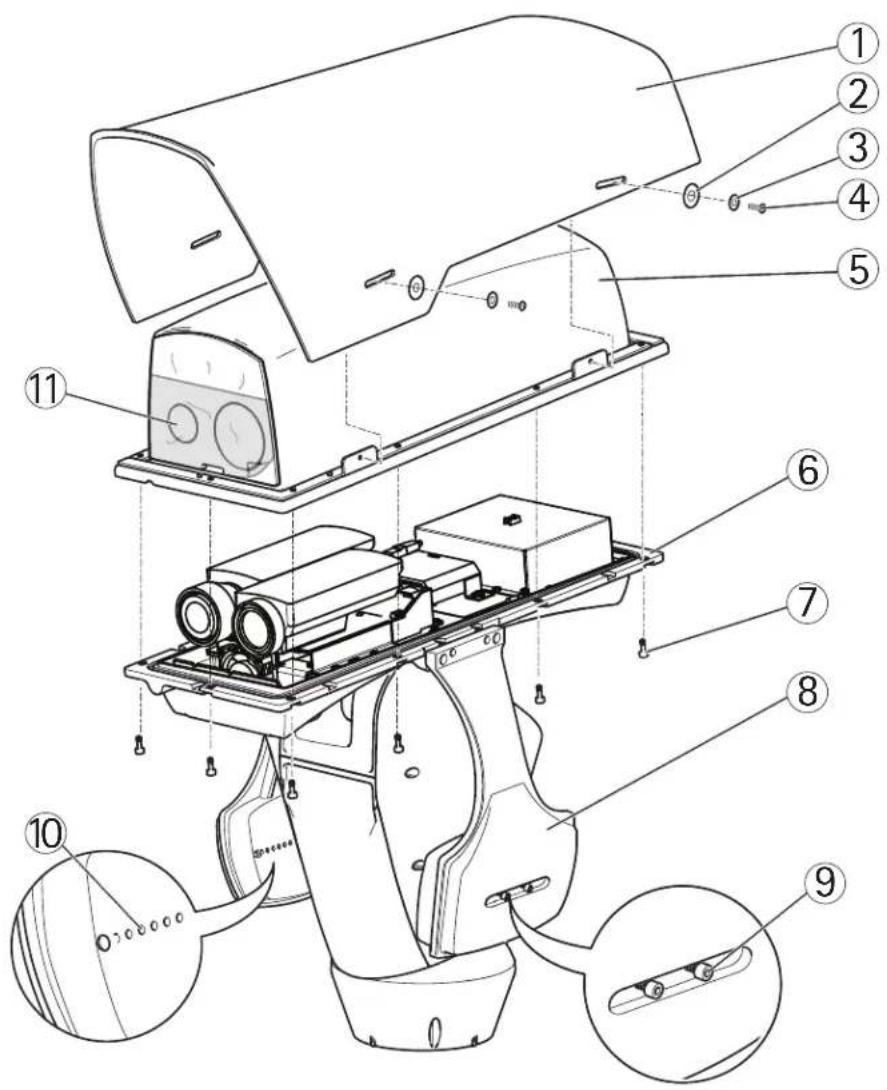
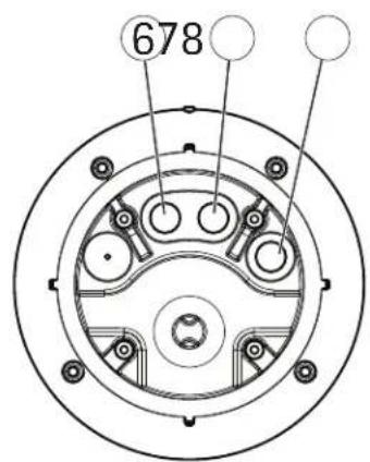
② Hardware Overview
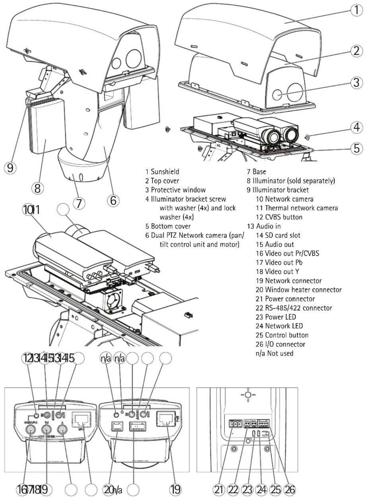
1 Sunshield
2 Top cover
3 Protective window
4 Illuminator bracket screw with washer (4x) and lock washer (4x)
5 Bottom cover
6 Dual PTZ Network camera (pan/tilt control unit and motor)
7 Base
8 Illuminator (sold separately)
9 Illuminator bracket
10 Network camera
11 Thermal network camera
12 CVBS button
13 Audio in
14 SD card slot
15 Audio out
16 Video out Pr/CVBS
17 Video out Pb
18 Video out Y
19 Network connector
20 Window heater connector
21 Power connector
22 RS-485/422 connector
23 Power LED
24 Network LED
25 Control button
26 I/O connector
n/a Not used
3 Install the Hardware
For information on the cameras' connectors, LED behaviors etc., see the respective User Manuals.
Install the Power Supply (sold separately)
WARNING
The mains supply shall be disconnected during installation.
NOTICE
The power supply specified with the product shall be used. Using any other power supply will void the warranty and could leave the unit at a risk.
Important
The day/night sensor is attached to the power supply (sold separately). If using the day/night sensor, place the power supply so that the sensor can track the changes in daylight.
- Install the power supply according to the instructions supplied with the power supply.
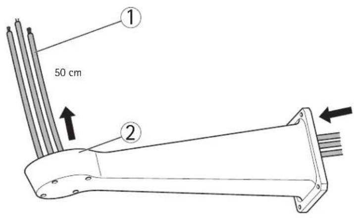
Install the Bracket (sold separately)
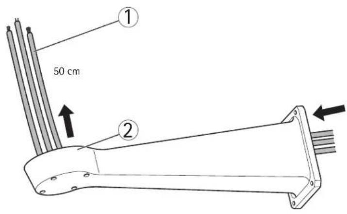
- Prepare a wall, parapet or pole for installation of the selected bracket (sold separately). See www.axis.com for information on available mounting accessories.
- Route the network, power and, if applicable, illuminator cables through the bracket. Leave approximately 50 cm (11.8") of cable for connecting the base.
NOTICE
Due to local regulations or the environmental and electrical conditions in which the product is to be used, a shielded network cable (STP) may be appropriate or required. Any network cables that are routed in outdoor environments or similar shall be shielded (STP) and intended for their specific use. Make sure that the network switch is properly grounded. See Electromagnetic Compatibility (EMC) for regulatory requirements.
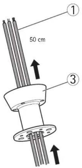

1 Network, power and illuminator cables
2 Wall bracket
3 Column bracket
- Install the selected bracket. Make sure that the screws and plugs are appropriate for the material (e.g. wood, metal, sheet rock, stone). Make sure that the bracket is secured properly and that the material is strong enough to support a weight of 35 kg (77.2 lb.).
Important
- Assemble the product in an upright position. Do not install the product upside down.
- When attaching the bracket to a concrete surface, use dowel pins with a traction torque rating of ≥ 300 dN.
-
When attaching the bracket to a metal surface, use screws with a diameter of at least 8 mm.
-
Assemble the screws, washers and screw seals.
- Put the seal in its position.

1 Screw seal (4x) 4 Screw (4x)
2 S e a l 5 C o l u m n b r a 3 W a s h e r (4 x) 6 W a
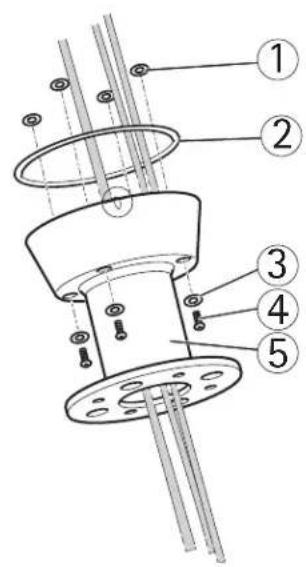
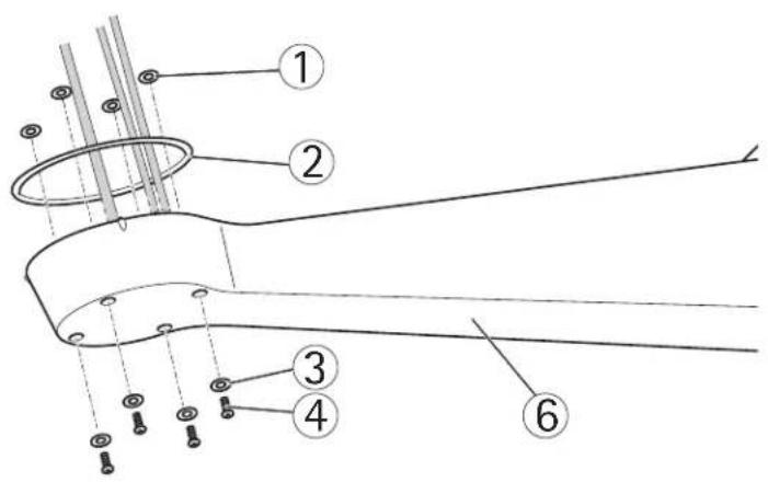
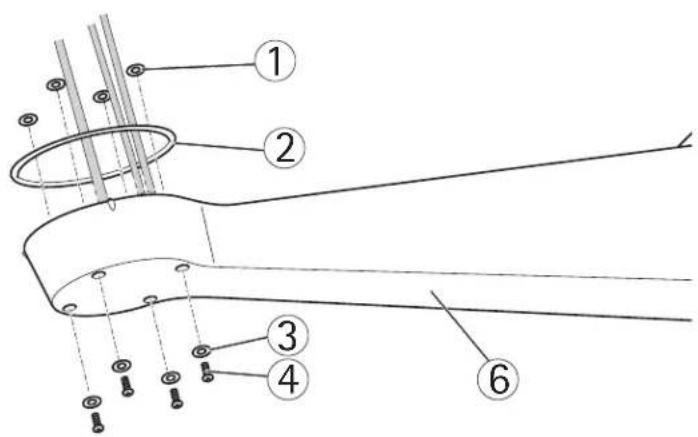
Attach the Base to the Bracket
- Remove the desiccant bag, which is placed in the base.
- Make sure the seal is in position.
- Route the network, power and, if applicable, illuminator cables through their respective cable glands in the base.
Important
The cable glands are suitable for cables with a diameter of 5 mm - 10 mm. For cables with a diameter 3 mm - 7 mm, use the supplied spare gaskets.
- Screw the cable gland caps on firmly.
NOTICE
It is important to tighten the cable gland caps in order to maintain the products IP rating.
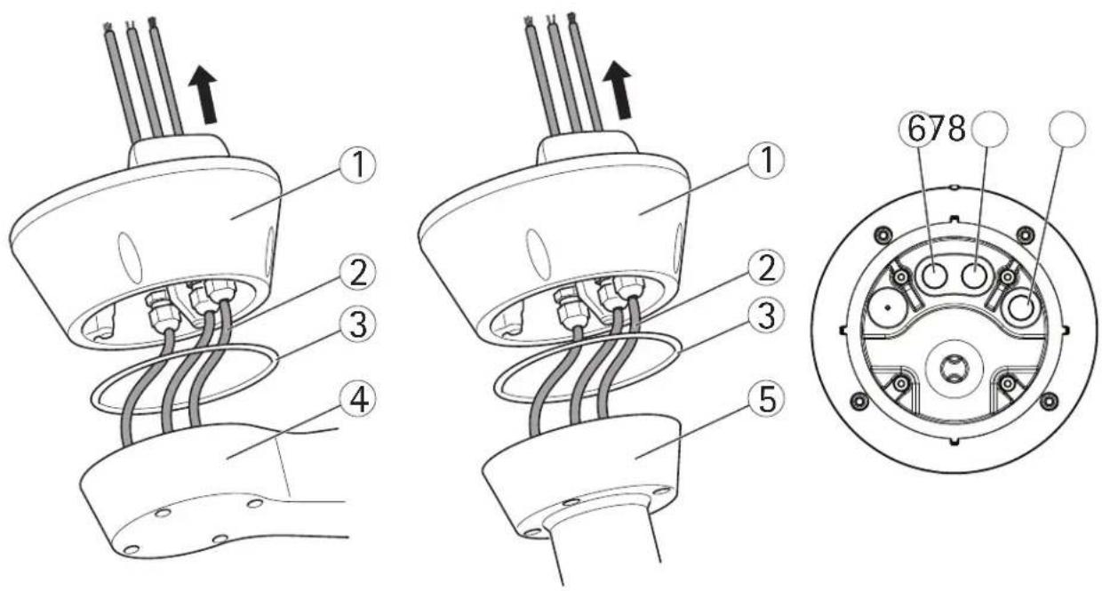
1 Base 5 Column bracket
2 Network, power and illuminator cables
3 Seal 8 Network cable
4 Wall bracket
6 Power cable (24 V AC)
7 Illuminator cable
- Attach the base to the bracket and tighten the screws (torque 4 Nm).
NOTICE
Apply Loctite 243 ^® threadlocker on the screws.
Important
The base can be attached to the bracket in four different positions. Use the alignment indicators on the different units to find a suitable position that allows access to the configuration board, which can be opened for easy access to the network connector, see illustration on page 12. This is useful for troubleshooting or for connecting an Axis installation display. The dip switches are configured with the correct PTZ protocol in the factory and do not need to be changed.
1 Base
2 Alignment indicator
3 S c r e w (
4 Column bracket
5 Wall bracket
- If applicable, connect the illuminator cable to the connector (ALARMS and 1) on the base.
- Using a RJ45 crimp tool, strip and crimp the network cable according to the manufacturer's instructions.
- Connect the network cable to the network connector on the base.
NOTICE
The power supply specified with the product shall be used. Using any other power supply will void the warranty and could leave the unit at a risk.
- 234Connect the 24 V AC power cable to the power connector on the base. Make sure the green/yellow ground wire is connected to the middle pin. To make the installation easier, it is possible to remove the connector from the circuit board and mount it when the cables are correctly connected.

1 Illuminator cable 4
Power cable (24 V AC, blue - L, green/yellow - 12 brown - N)
2 Network connector 5 Power connector (24 V AC)
3 N e t w o r k c a b l e
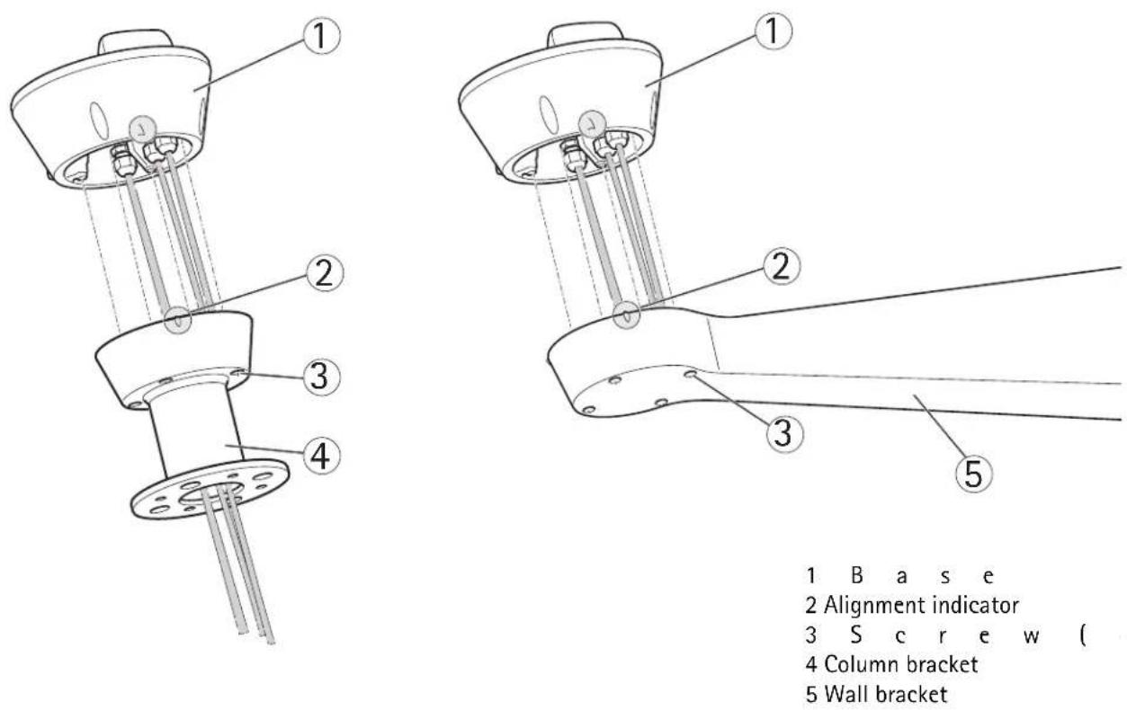
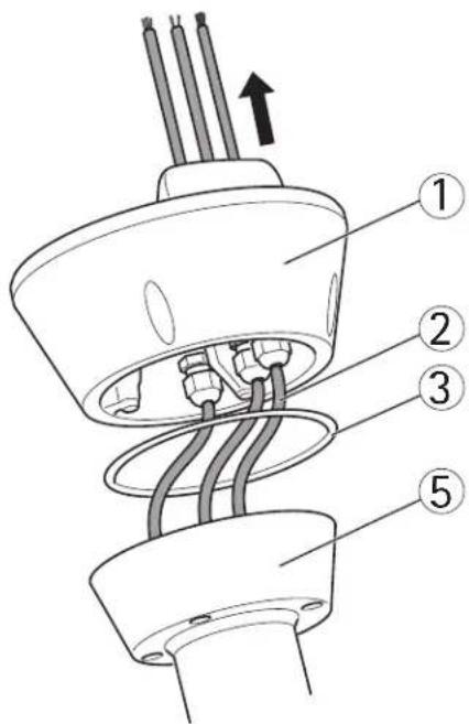
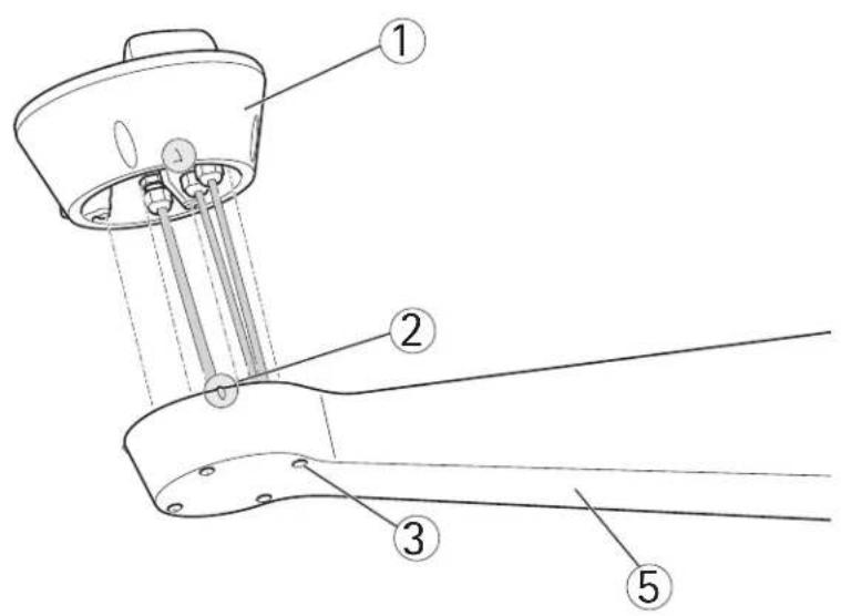
Attach the AXIS Q87-E Dual PTZ Network Camera Series to the Base
- Make sure the seal is in position.
- Remove the sunshield, which is placed on but not attached to, from the top cover.
- Attach the Pan/Tilt control unit, motor and camera assembly to the base and tighten the screws (torque 4 N m).
NOTICE
Use the alignment indicators to align the units. Incorrect alignment could cause damage to components.
1 Pan/Tilt control unit, motor and camera assembly 4 S e a l 5 B a s e
2 Configuration board lid 6 Washer (4x)
3 Alignment indicators 7 Screw (4x)
-
Aim the dual PTZ network camera to the point of interest and focus the thermal network camera if required, see Focus Adjustment - AXIS Q1921/AXIS Q1922, on page 18. See Access the Video Stream, on page 18 and the Installation and Management Software CD for information on how to view the video stream.
-
Install the counterweights, see Install the Counterweights, on page 14 or install the selected illuminators (sold separately), see page 16. Infrared LED Illuminators are available as accessories, see www.axis.com for information of available illuminators.
NOTICE
Either counterweights or illuminators shall be installed. Any other installation method will void the warranty and could leave the unit at a risk
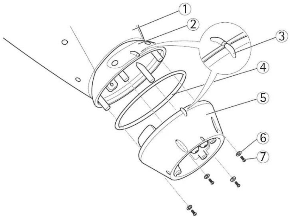
Install the Counterweights
- Unscrew the bottom cover screws and remove the top cover, see illustration on page 15.
- Attach the counterweights to the bottom cover using the supplied screws and washers (torque 4 Nm).
NOTICE
Apply Loctite 243 ^® threadlocker on the screws.
- Secure the counterweights using the supplied grub screws (torque 4 Nm).
1 B o t t o m
2 G r u b s c r
3 Washer
4 S c r e w ( 4
5 Counterweight (2x)
- Attach the top cover to the bottom cover. Make sure to tighten diagonally opposite bottom cover screws a few turns at a time until all are tight (torque 4 Nm). This will help ensure that the bottom cover gasket is compressed evenly.
- Attach the sunshield to the top cover.
- Loosen the counterweight locking screws and adjust the position of the weights to the desired position. The positions of the weights must be identical.
Note: The pan/tilt assembly must remain balanced for the pan/tilt function to operate correctly. Check the balance by swinging the housing slightly.
- Remove the protective plastic from the protective window.
1 Sunshield 7 Bottom cover screw (10x)
2 Washer (4x) 8 Counterweight
3 Lock washer (4x) 9 Counterweight locking screws
4 Sunshield screw (4x) 10 Positioning holes
5 Top cover 11 Protective plastic
6 Bottom cover
- Switch on the mains supply. The pan/tilt control unit will start turning and the cameras will turn on approximately 30 seconds later. In cold temperatures, there might be a delay due to the de-icing process, see Day/Night Sensor, on page 17.
CAUTION
Risk of pinching. Do not touch the product while it is moving.
Install the Illuminators (sold separately)
See the Installation Guide provided with the illuminators for instructions on how to install the illuminators (sold separately).
Composite Video (Optional AXIS Q1755)
For information how to connect composite video in/out, see AXIS Q1755 User Manual.
4 Configuration
For information about how to assign an IP address and gain access to the product, see Access the Video Stream, on page 18 and the Installation and Management Software CD.
PTZ
The PTZ functionality is controlled through the network camera. The PTZ controls will be available from the Live View page in the network camera's web pages after enabling the PTZ functionality. See the User Manual, available at www.axis.com
Day/Night Sensor
The day/night sensor is attached to the power supply (sold separately).
The product is configured in the factory for optimal performance in a range of conditions. However, settings can be adjusted to suit specific conditions on site.
To adjust the sensitivity of the day/night sensor, turn the potentiometer until it reaches the desired threshold. Turn the potentiometer clockwise to increase the threshold and advance the switch to night mode. Turn the potentiometer counterclockwise to decrease the threshold and delay the switch to night mode. The switch to night mode will activate the illuminators (sold separately).
De-icing
The product's automatic de-icing process starts when the air temperature is below 0^ (32 °F) required that the product is switched on. The de-icing process ensures that the product works properly even at low temperatures. The de-icing period lasts 90 minutes and during this period both cameras are turned off.
5 Access the Video Stream
Use the tools provided on the Installation and Management Software CD to assign an IP address, set the password and access the video stream. This information is also available from the support pages on www.axis.com/techsup
Focus Adjustment - AXIS Q1921/AXIS Q1922
If required, follow these instructions to focus the thermal network camera:
- Unscrew the stop screw on the lens, using a slotted screwdriver 1.8 mm.
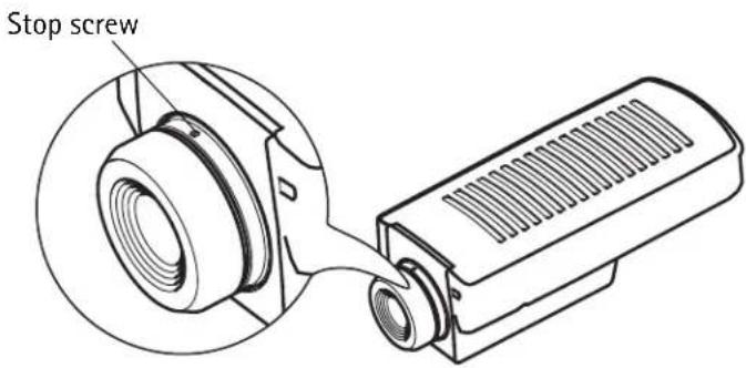
- Focus the camera to the appropriate distance. See the table below for recommended focus distances for achieving optimal focus both for near focus and infinity.
| Camera and lens 35 mm 60 | mm | |
| AXIS Q1921 | 22 m (72 ft.) 60 m | (200 ft.) |
| AXIS Q1922 | 33 m (110 ft.) 90 m | (300 ft.) |
- Secure the stop screw.
Note
The network camera has a lens with autofocus and cannot be adjusted manually.
Resetting to the Factory Default Settings
This will reset all parameters, including the IP address, to the Factory Default settings:
- Disconnect power from the camera.
- Press and hold the control button and reconnect power.
- Keep the control button pressed until the status indicator displays amber (this may take up to 15 seconds).
- Release the control button. When the status indicator displays green (which can take up to 1 minute) the process is complete and the camera has been reset.
- Re-assign the IP address.
It is also possible to reset parameters to the original factory default settings via the web interface. For more information, please see the online help or the User Manual.
Troubleshooting
This table applies to the pan/tilt and illumination units only. For troubleshooting of the network cameras, see the respective User Manuals.
WARNING
Disconnect the mains supply before performing any kind of maintenance procedure.
| The product is not running | Make sure all the connections are correct. |
| The product does not move | Make sure that the power supply cable is intact and connected correctly. |
| The pan/tilt is disabled during the de-icing process, see De-icing, on page 17. | |
| The product moves, but is unresponsive to commands | Check that the PTZ functionality is enabled, see PTZ, on page 17. |
| Make sure that the RS-485 cable is intact and connected correctly. | |
| The illuminators are not turning on when day changes into night. | Make sure all the connections are correct. |
| Make sure the day/night sensor is positioned so it can track the changes in daylight. | |
| Adjust the potentiometer, see Day/Night Sensor, on page 17. |
Technical Specifications
For technical specifications of the network cameras, see the respective User Manuals.
| Function/group Item Specifications | ||
| Camera Model AX | S Q8721-E, includes AXIS Q1755 and AXIS Q1921AXIS Q8722-E, includes AXIS Q1755 and AXIS Q1922 | |
| General Pan/Tilt Pan: 360° endless, 0.1° - 20°/sTilt: +45° to -20°, 0.1° - 20°/s | ||
Further Information
Visit www.axis.com/techsup to check if there is updated firmware available for your network product. To see the currently installed firmware version, see Setup > About.
Visit Axis learning center www.axis.com/academy for useful trainings, webinars, tutorials and guides.
Warranty
For information about Axis' product warranty and thereto related information, see www.axis.com/warranty
Mesures de sécurité
1 Joint à vis (4x) 4 Vis (4x)
2 Joint 5 Support colonne
3 Rondelle (4x) 6 Support mural

1 Fuß
2 Ausrichtungsmarke
3 S c h r a u t
4 Halterung für
Säulenmontage
5 Wandhalterung


1 Juntas de tornillos (4) 4 Tornillos (4)
2 J u n t a 5 E s c u a d r a
3 Arandelas (4) 6 Escuadra de pared
Fijar la base a la escuadra

1 Base
Enfoque: AXIS Q1921/AXIS Q1922
natural_image
Technical line drawing of a mechanical component with a cylindrical housing and a rectangular housing (no text or symbols)Installation Guide Rev. 2.1
AXIS Q87-E Printed: February 2013
© Axis Communications AB, 2013 Part No. 50369
- Legal Considerations
- Trademark Acknowledgments
- Electromagnetic Compatibility (EMC)
- Safety
- Photobiological Safety
- Equipment Modifications
- Liability
- RoHS
- WEEE Directive
- Support
- Contact Information
- Safeguards
- ⚠ CAUTION
- NOTICE
- Important
- Transportation
- Battery Replacement
- WARNING
- AXIS Q87-E Installation Guide
- Installation Steps
- Package Contents
- Install the Hardware
- Install the Power Supply (sold separately)
- Install the Bracket (sold separately)
- Attach the Base to the Bracket
- Attach the AXIS Q87-E Dual PTZ Network Camera Series to the Base
- Install the Counterweights
- CAUTION
- Install the Illuminators (sold separately)
- Composite Video (Optional AXIS Q1755)
- Configuration
- PTZ
- Day/Night Sensor
- De-icing
- Access the Video Stream
- Focus Adjustment - AXIS Q1921/AXIS Q1922
- Note
- Resetting to the Factory Default Settings
- Troubleshooting
- Technical Specifications
- Further Information
- Warranty
- Mesures de sécurité
- Fijar la base a la escuadra
- Enfoque: AXIS Q1921/AXIS Q1922
Brand : AXIS
Model : Q8722-E
Category : Surveillance Camera