
TA-F5000 - Receiver SONY - Free user manual and instructions
Find the device manual for free TA-F5000 SONY in PDF.


| Product Type | Integrated stereo receiver |
| Brand | Sony |
| Model | TA-F5000 |
| Dimensions (W x H x D) | 430 x 140 x 300 mm |
| Weight | 8 kg |
| Power supply | 220-240 V, 50/60 Hz |
| Power consumption | 200 W (max) |
| Output power | 2 x 100 W into 8 ohms (RMS) |
| Recommended speaker impedance | 4-16 ohms |
| Audio inputs | Phono (MM), CD, Tuner, Aux, 2 x Tape |
| Audio outputs | Speakers (A/B), Headphones, Pre-out, Tape |
| Frequency response | 10 Hz - 50 kHz ±1 dB |
| Signal-to-noise ratio | 90 dB (line) |
| Total harmonic distortion | 0.01% (at 1 kHz, 50 W) |
| Main functions | Input selector, volume, balance, bass/treble, loudness, muting, speakers A/B |
| Maintenance and cleaning | Wipe with a soft, dry cloth. Do not use abrasive products or solvents. |
| Safety | Do not expose to humidity, dripping or splashing. Unplug during thunderstorms or prolonged non-use. |
| Spare parts and repairability | Contact an authorized Sony service center. Parts available under reference. |
| General information | Manual available in several languages at notice-facile.com |
| Included accessories | Power cord, user manual |
Frequently Asked Questions - TA-F5000 SONY
User questions about TA-F5000 SONY
0 question about this device. Answer the ones you know or ask your own.
Ask a new question about this device
Download the instructions for your Receiver in PDF format for free! Find your manual TA-F5000 - SONY and take your electronic device back in hand. On this page are published all the documents necessary for the use of your device. TA-F5000 by SONY.
USER MANUAL TA-F5000 SONY
Integrated Stereo Amplifier
Operating Instructions GB
To avoid electrical shock, do not open the cabinet. Refer servicing to qualified personnel only.
Do not install the appliance in a confined space, such as a bookcase or built-in cabinet.
Precautions
On safety
- Do not disassemble the cabinet as this may result in an electrical shock. Refer servicing to qualified personnel only.
- Should any solid object or liquid fall into the cabinet, unplug the amplifier and have it checked by qualified personnel before operating it any further.
On power sources
- Before operating the amplifier, check that the operating voltage of the amplifier is identical with your local power supply. The operating voltage is indicated on the nameplate at the rear of the amplifier.
- If you are not going to use the amplifier for a long time, be sure to disconnect the amplifier from the wall outlet. To disconnect the AC power cord (mains lead), grasp the plug itself; never pull the cord.
On placement
- Place the amplifier in a location with adequate ventilation to prevent heat built-up and prolong the life of the amplifier.
- Do not place the amplifier near heat sources, or in a place subject to direct sunlight, excessive dust or mechanical shock.
- Do not place anything on top of the cabinet that might block the ventilation holes and cause malfunctions.
On operation
Before connecting other components, be sure to turn off and unplug the amplifier.
On cleaning the amplifier
Clean the cabinet, panel and controls with a soft cloth slightly moistened with a mild detergent solution. Do not use any type of abrasive pad, scouring powder or solvent such as alcohol or benzine.
On the prevention of howling
Do the following:
—lower the volume.
—keep the turntable as far from the speakers as possible.
—use commercially available audio insulators on the bottom of the turntable.
—keep the microphone away from the speakers during use.
For further protection against howling, set the speakers or turntable on top of a heavy wooden board or concrete slab.
If you have any questions or problems concerning your amplifier, please consult your nearest Sony dealer.
Welcome!
Thank you for purchasing the Sony Integrated Stereo Amplifier. Before operating the amplifier, please read this manual thoroughly and retain it for future reference.
TABLE OF CONTENTS
Getting Started
Unpacking 4
Hookup Overview 4
Audio Component Hookups 5
Speaker System Hookups 6
Mains Lead Hookups 7
About This Manual
Conventions
The following icon is used in this manual:

Indicates hints and tips for making the task easier.
Listening to the Music 8
Recording 10
Additional Information
Troubleshooting 11
Specifications 11
Front and Rear Panel Descriptions 12
Unpacking
Check that you have received the following supplied items:
- Shorting plugs* (2)
- Mains lead (1)
* plugged into the PHONO jacks when shipped from the factory
Hookup Overview
The amplifier allows you to connect and control the following audio components. Follow the hookup procedure indicated for each component that you want to connect.
To learn the location and name of each jack, see "Front and Rear Panel Descriptions" on page 12.
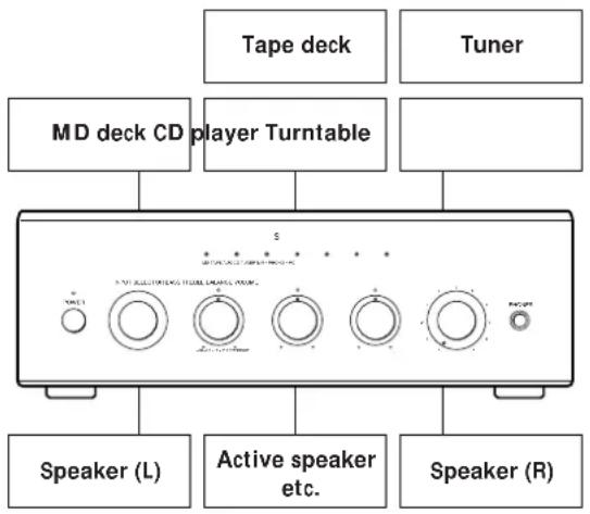
Before you get started
- Turn off the power to all components before making any connections.
- Do not connect the mains leads of the various components until all connections are completed.
- Use the audio connecting cords supplied with each component for hooking up with the amplifier. Purchase and use optionally available cords as required.
- Be sure to make connections firmly to prevent hum and noise.
- When connecting an audio connecting cord, be sure to match the R (right) and L (left) jacks on the amplifier to the R and L jacks on the other components.
Audio Component Hookups
Overview
Here you learn how to connect your audio components to the amplifier.

What cords will I need?
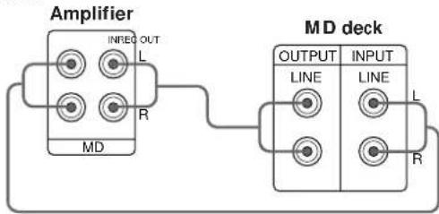
Audio connecting cords (not supplied) (1 for each component and turntable; 2 for each tape deck, or MD deck)

Hookups
The arrow indicates signal flow.
Tuner
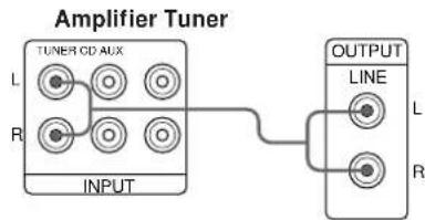
flowchart
graph LR
    A["INPUT"] --> B["TUNER CD AUX"]
    B --> C["OUTPUT LINE"]
    C --> D["L"]
    C --> E["R"]
CD player

flowchart
graph LR
    A["Amplifier"] --> B["TUNER CD AUX"]
    B --> C["CD player"]
    C --> D["L LINE OUT"]
    C --> E["R"]
Tape deck

MD deck
Turntable
1 Remove the shorting plugs from the PHONO jacks before connecting the cables.
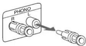
Notes
- Do not insert the shorting plugs into the MD REC OUT, TAPE REC OUT, or PRE OUT jacks. Doing so may stop output from the amplifier or cause the unit to malfunction.
- Leave the shorting plugs in the PHONO jacks if you do not connect a turntable. Removing the shorting plugs without connecting a turntable may cause noise in the audio signal.
2 Connect the audio connecting cords.

• If your turntable has an earth lead
To prevent hum, connect the earth lead to the y earth terminal on the amplifier.
TV or VCR
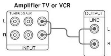
flowchart
graph LR
    A["INPUT"] --> B["TUNER CD AUX"]
    B --> C["LINE"]
    C --> D["OUTPUT"]
Active speaker, etc.

Speaker System Hookups
Overview
Here you learn how to connect a pair of speakers to the amplifier. You can make either normal or bi-wire connections.
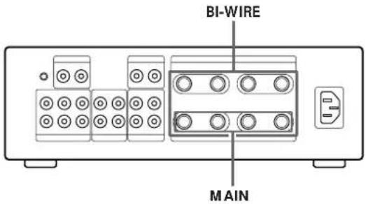
What cords will I need?
Speaker cord (not supplied) (1 for each speaker/2 for each bi-wired speaker)

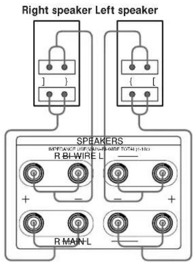
Twist the stripped ends of the cord about 2/3 inch (15 mm). Be sure to match the speaker cord to the appropriate terminal on the components: + to + and - to -. If the cords are reversed, the sound will be distorted and will lack bass. We recommend designating the striped (or marked) speaker cord as "+" to help to prevent an accidental polarity mismatch.
Hookups
To connect the speaker cords

natural_image
Diagram showing three types of connectors with labeled parts, no text or symbols presentConnecting to normal speakers

Connect the speakers to the MAIN terminals on the amplifier.
Note
Use speakers with a nominal impedance of 4 to 16 ohms.
Connecting to bi-wire system speakers
Since the MAIN and BI-WIRE terminals provide simultaneous output, you can use them to bi-wire a pair of compatible speakers. Connect the BI-WIRE terminals to the speaker's high frequency driver and connect the MAIN terminals to the speaker's low (or mid) frequency driver.
Note
When outputting at the same time to two speaker systems or connecting to a bi-wire system speaker, use speakers with a nominal impedance of 8 to 16 ohms.
Mains Lead Hookups
Do the following to connect this amplifier to a wall outlet after you have completed all the previous connections.

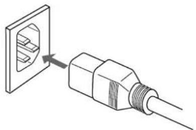
1 Connect the supplied mains lead to the AC IN (230 V) terminal.
natural_image
Diagram of a plug with internal socket connected to a terminal outlet (no text or symbols)2 Connect the other end of the supplied mains lead to a wall outlet.
Note
Separate the mains lead, audio connecting cords and speaker cords. Noise or sound deterioration may occur when audio connecting cords are in contact with the mains lead, or when the mains lead or speaker cords are placed near the tuner's loop aerial or aerial wire.
Listening to the Music
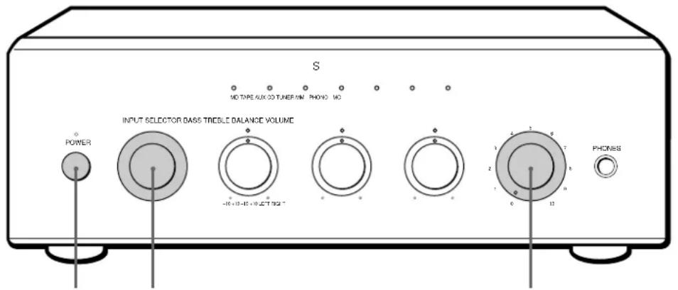
2,634
1 Turn on the programme source you want to listen to.
2 Turn VOLUME fully counterclockwise (to "0") to prevent damaging the speakers with excessive output.
3 Press POWER to turn on the amplifier.
The POWER indicator changes from red to green.
4 Set INPUT SELECTOR to the respective programme source. The indicator for the selected programme source lights up.
| To listen to a | Turn INPUT SELECTOR to |
| Record | PHONO MC*/MM* |
| Radio broadcast | TUNER |
| Compact disc | CD |
| Source connected to AUX | AUX |
| Cassette tape | TAPE |
| Mini disc | MD |
* Select MC or MM according to the type of cartridge you are using.
5 Play the programme source.
6 Adjust the volume level by turning VOLUME.


To listen through headphones
Connect a pair of headphones to PHONES. No sound comes from the speakers.

To avoid damaging the amplifier or speakers
We recommend the following procedure for turning off the power.
1 Turn VOLUME fully counterclockwise (to "0").
2 Turn off the amplifier.
3 Turn off the programme source.
| To adjust | Turn |
| the bass | BASS |
| the treble | TREBLE |
| the balance | BALANCE |
To avoid howling
This phenomenon, called “acoustic feedback”, occurs when vibrations from the speakers are transmitted through the air or via solid objects (such as shelves, a cabinet, or the floor) to the stylus of a turntable (or to a microphone), amplified and reproduced through the speakers again.
If howling occurs, it may damage the speakers or cause the connected components to malfunction. If howling occurs, check the following.
- Turn VOLUME down.
- Move speakers away from the turntable.
- Place the turntable on the solid surface.
- Use commercially available audio insulator.
- When using a microphone, move the microphone away from speakers.
To further reduce the possibility of howling, place the speakers or turntable on a heavy board, such as one made of concrete.
Note
Continuous output at high levels that cause the sound to distort.
Basic Operations
Recording


You can record to two components simultaneously
When both a cassette deck and MD deck are connected, the selected programme source can be recorded by both decks.

To avoid damaging the amplifier or speakers
We recommend the following procedure for turning off the power.
1 Turn VOLUME fully counterclockwise (to "0").
2 Turn off the amplifier.
3 Turn off the components.
1 Turn on the programme source you want to record.
2 Press POWER to turn on the amplifier.
The POWER indicator changes from red to green.
3 Select the programme source that you want to record by turning INPUT SELECTOR.
| To record from | Turn INPUT SELECTOR to |
| Record | PHONO MC*/MM* |
| Radio broadcast | TUNER |
| Compact disc | CD |
| Source connected to AUX | AUX |
| Cassette tape | TAPE |
| Mini disc | MD |
* Select MC or MM according to the type of cartridge you are using.
4 Prepare the recording component to record, then start recording.
5 Start playing the programme source.
The adjustment of the tone or volume level does not effect the recorded sound.
To stop recording
1 Stop recording of the recording component.
2 Stop playback on the playing component.
Troubleshooting
If you've experience any of the following difficulties while using the amplifier, use this troubleshooting guide to help you remedy the problem. Should any problem persist, consult your nearest Sony dealer.
No sound output.
/ Connect the audio connecting cords firmly.
/ Connect the amplifier and other audio components correctly.
/ Turn INPUT SELECTOR to the appropriate programme source.
No audio from one channel or unbalanced speaker output.
/ Turn BALANCE to adjust the balance.
/ Check the speaker and input connections of silent channel.
Sudden loss of audio and the POWER indicator lights up red.
/ The speaker cords have been shorted. Make sure they are connected correctly.
Weak bass or treble.
/ Adjust the BASS or TREBLE control.
/ Turn INPUT SELECTOR to select the appropriate cartridge type (see page 8).
/ Change speaker positions or room conditions to eliminate obstructions in sound path.
Distorted sound.
/ Improperly selected input signal.
/ Insufficient input capacity of speakers. Lower the volume.
Lack of bass or ambiguity in instrument positions.
/ Speaker cord and terminal polarity are reversed. Reconnect the cords with correct polarity.
Hum or noise.
/ Ground the turntable system (see page 5).
/ Connect the audio connecting cords firmly.
/ The amplifier is picking up interference from a TV set. Move the amplifier away from the TV set or turn the TV set off.
Cannot record.
/ Turn INPUT SELECTOR to the appropriate programme source.
Specifications
System
Power Amplifier: Pure-complementary SEPP MOS FET power amplifier with all stages directly coupled Preamplifier: Low-noise, high-gain equalizer amplifier + MC head amplifier Power section: Large-capacity power supply advanced STD
Rated output 45 W + 45W (DIN) (at 4 ohms) 35 W + 35W (RMS, 20 Hz to 20 kHz)
Speaker impedance 4 to 16 ohms
Total harmonic distortion 0.008% (at 8 ohms, 10 W output)
Damping factor 150
Frequency response TUNER, CD, AUX, TAPE, MD: 7 Hz to 100 kHz ^+ dB PHONO: 20 Hz to 20 kHz ± 3 dB
Inputs
Input sensitivity and impedance PHONO MC: 0.18 mV, 100 ohms MM: 1.6 mV, 50 kilohms TUNER, CD, AUX, TAPE, MD: 150 mV, 20 kilohms
S/N PHONO MC:75 dB (A Fil, 0.5 mV) MM: 85 dB (A Fil, 5 mV) TUNER, CD, AUX, TAPE, MD: 100 dB (input short)
Outputs
Output level / impedance MD REC OUT, TAPE REC OUT: 150 mV, 1 kilohm PRE OUT: 600 mV, 200 ohms
Phones output Corresponding to Low/High impedance headphones: 10 mW (8 ohms)
Tone controls BASS (100 Hz): ±6 dB TREBLE (10 kHz): ±6 dB
General
Power requirements 220 - 230 V AC, 50/60 Hz
Power consumption 100 W
Dimensions (approx.) 280 x 100 x 400 mm (w/h/d) (11 × 3^15/16 × 15^3/4 inches) incl. projecting parts and controls
Mass (approx.) 7.0 kg (15 lb 7 oz)
Supplied accessories
Shorting plug* (2) Mains lead (1)
* plugged into the PHONO jacks when shipped from the factory
Design and specifications are subject to change without notice.
Front and Rear Panel Descriptions
Refer to the pages in parenthesis for details.
Front panel

1 POWER (8)
2 Input source indicator (8, 10)
3 PHONES (9)
4 VOLUME (8)
5 BALANCE (9)
6 TREBLE (9)
7 BASS (9)
8 INPUT SELECTOR (8, 10)
Rear panel

1 y earth terminal (5)
2 PHONO (5)
3 TAPE (5)
4 PRE OUT (5)
5 AC IN (230 V) (7)
6 SPEAKERS (6)
7 MD (5)
8 AUX (5)
9 CD (5)
0 TUNER (5)
AVERTISSEMENT
Tourne-disque
Remarques
natural_image
Two coaxial cable connectors with threaded ends, shown in line drawing without any text or symbols.natural_image
Diagram of a plug with internal socket and connector, showing connection to a terminal block (no text or symbols)Notas
natural_image
Diagram of two coaxial connectors with coiled wires, no text or symbols presentnatural_image
Diagram of a plug with internal socket connected to a cable (no text or symbols)| Masa (aprox.) | 7,0 kg |
Nota
natural_image
Two identical electrical connectors labeled 1 and 3, each with a coiled cable (no text or symbols beyond labels)natural_image
Diagram of a plug with internal socket connected to a terminal outlet (no text or symbols)| Peso (aprox.) | 7,0 kg |
1 Terminal y terra (5)
7 MD do deck de MDs (5)
Hinweise
natural_image
Diagram showing three types of connectors with labeled parts, no text or symbols presentnatural_image
Diagram of a plug with internal socket connected to a terminal block (no text or symbols)Aansluitingen
Platenspeler
Opmerkingen
natural_image
Diagram showing three types of connectors with labels 1 and 2, no text or symbols presentnatural_image
Diagram of a plug with internal socket connected to a terminal outlet (no text or symbols)OBS!
natural_image
Diagram showing three types of connectors with labeled parts, no text or symbols presentOBS!
natural_image
Diagram of a plug with internal socket connected to a terminal block (no text or symbols)Collegamenti
Giradischi
Note
Cavi necessari
natural_image
Diagram showing three types of connectors with labeled parts, no text or symbols presentnatural_image
Diagram of a plug with internal socket connected to a terminal outlet (no text or symbols)| Massa (circa) | 7,0 kg |
- Integrated Stereo Amplifier
- Precautions
- On safety
- On power sources
- On placement
- On operation
- On cleaning the amplifier
- On the prevention of howling
- Welcome!
- TABLE OF CONTENTS
- Getting Started
- About This Manual
- Conventions
- Listening to the Music 8
- Recording 10
- Additional Information
- Unpacking
- Hookup Overview
- Before you get started
- Audio Component Hookups
- Overview
- What cords will I need?
- Hookups
- Turntable
- Notes
- Speaker System Hookups
- Connecting to normal speakers
- Note
- Connecting to bi-wire system speakers
- Mains Lead Hookups
- Listening to the Music
- To listen through headphones
- To avoid damaging the amplifier or speakers
- To avoid howling
- Basic Operations
- Recording
- You can record to two components simultaneously
- To stop recording
- Troubleshooting
- No sound output.
- No audio from one channel or unbalanced speaker output.
- Sudden loss of audio and the POWER indicator lights up red.
- Weak bass or treble.
- Distorted sound.
- Lack of bass or ambiguity in instrument positions.
- Hum or noise.
- Cannot record.
- Specifications
- System
- Inputs
- Outputs
- General
- Supplied accessories
- Front and Rear Panel Descriptions
- AVERTISSEMENT
- Tourne-disque
- Remarques
- Notas
- Nota
- Hinweise
- Aansluitingen
- Platenspeler
- Opmerkingen
- OBS!
- Collegamenti
- Giradischi
- Cavi necessari
Brand : SONY
Model : TA-F5000
Category : Receiver