PDP-R06G - TV PIONEER - Free user manual and instructions
Find the device manual for free PDP-R06G PIONEER in PDF.

User questions about PDP-R06G PIONEER
0 question about this device. Answer the ones you know or ask your own.
Ask a new question about this device
Download the instructions for your TV in PDF format for free! Find your manual PDP-R06G - PIONEER and take your electronic device back in hand. On this page are published all the documents necessary for the use of your device. PDP-R06G by PIONEER.
USER MANUAL PDP-R06G PIONEER
Pioneer sound.vision.soul
PLASMA DISPLAY SYSTEM
SISTEMA DE PANTALLA DE PLASMA
SISTEMA DE MONITOR DE PLASMA
等離子顯示器系統
PDP-506HDG PDP-436HDG
Operating Instructions
The lightning flash with arrowhead symbol, within an equilateral triangle, is intended to alert the user to the presence of uninsulated "dangerous voltage" within the product's enclosure that may be of sufficient magnitude to constitute a risk of electric shock to persons.
CAUTION
RISK OF ELECTRIC SHOCK DO NOT OPEN
CAUTION:
TO PREVENT THE RISK OF ELECTRIC SHOCK, DO NOT REMOVE COVER (OR BACK). NO USER-SERVICEABLE PARTS INSIDE. REFER SERVICING TO QUALIFIED SERVICE PERSONNEL.

The exclamation point within an equilateral triangle is intended to alert the user to the presence of important operating and maintenance (servicing) instructions in the literature accompanying the appliance.
CAUTION
The POWER switch on this unit will not completely shut off all power from the AC outlet. Since the power cord serves as the main disconnect device for the unit, you will need to unplug it from the AC outlet to shut down all power. Therefore, make sure the unit has been installed so that the power cord can be easily unplugged from the AC outlet in case of an accident. To avoid fire hazard, the power cord should also be unplugged from the AC outlet when left unused for a long period of time (for example, when on vacation).
D3-4-2-2-2a_A_En
WARNING
This equipment is not waterproof. To prevent a fire or shock hazard, do not place any container filed with liquid near this equipment (such as a vase or flower pot) or expose it to dripping, splashing, rain or moisture.
D3-4-2-1-3_A_En
NOTE: This equipment has been tested and found to comply with the limits for a Class B digital device, pursuant to Part 15 of the FCC Rules. These limits are designed to provide reasonable protection against harmful interference in a residential installation. This equipment generates, uses, and can radiate radio frequency energy and, if not installed and used in accordance with the instructions, may cause harmful interference to radio communications. However, there is no guarantee that interference will not occur in a particular installation. If this equipment does cause harmful interference to radio or television reception, which can be determined by turning the equipment off and on, the user is encouraged to try to correct the interference by one or more of the following measures:
— Reorient or relocate the receiving antenna.
— Increase the separation between the equipment and receiver.
— Connect the equipment into an outlet on a circuit different from that to which the receiver is connected.
— Consult the dealer or an experienced radio/TV technician for help.
D8-10-1-2_En
CAUTION: This product satisfies FCC regulations when shielded cables with Ferrite-cores attached and connectors are used to connect the unit to other equipment. To prevent electromagnetic interference with electric appliances such as radios and televisions, use shielded cables with Ferrite-cores attached and connectors for connections.
D8-10-3b_En
FEDERAL COMMUNICATIONS COMMISSION DECLARATION OF CONFORMITY
This device complies with part 15 of the FCC Rules. Operation is subject to the following two conditions: (1) This device may not cause harmful interference, and (2) this device must accept any interference received, including interference that may cause undesired operation.
Product Name: Plasma Display System
(Plasma Display)
(Media Receiver)
Model Number: PDP-506HDG PDP-436HDG
(PDP-506PG) (PDP-436PG)
(PDP-R06G) (PDP-R06G)
Product Category: Class B Personal Computers & Peripherals
Responsible Party Name: PIONEER ELECTRONICS SERVICE, INC.
Address: 1925 E. DOMINGUEZ ST. LONG BEACH, CA 90801-1760, U.S.A.
Phone: 310-952-2915
For Business Customer URL
http://www.PioneerUSA.com
Information to User
Alteration or modifications carried out without appropriate authorization may invalidate the user's right to operate the equipment.
WARNING
Before plugging in for the first time, read the following section carefully.
The voltage of the available power supply differs according to country or region. Be sure that the power supply voltage of the area where this unit will be used meets the required voltage (e.g., 230V or 120V) written on the rear panel.
D3-4-2-1-4_A_En
WARNING
This product equipped with a three-wire grounding (earthed) plug - a plug that has a third (grounding) pin. This plug only fits a grounding-type power outlet. If you are unable to insert the plug into an outlet, contact a licensed electrician to replace the outlet with a properly grounded one. Do not defeat the safety purpose of the grounding plug. D3-4-2-1-6_A_En
The following symbols are found on labels attached to the product. They alert the operators and service personnel of this equipment to any potentially dangerous conditions.

WARNING
This symbol refers to a hazard or unsafe practice which can result in personal injury or property damage.

CAUTION
This symbol refers to a hazard or unsafe practice which can result in severe personal injury or death.
WARNING
To prevent a fire hazard, do not place any naked flame sources (such as a lighted candle) on the equipment.
D3-4-2-1-7a_A_En
VENTILATION CAUTION
When installing this unit, make sure to leave space around the unit for ventilation to improve heat radiation. For the minimum space required, see page 15.
WARNING
Slots and openings in the cabinet are provided for ventilation to ensure reliable operation of the product, and to protect it from overheating. To prevent fire hazard, the openings should never be blocked or covered with items (such as newspapers, table-cloths, curtains) or by operating the equipment on thick carpet or a bed.
STANDBY/ON Button
STANDBY: When placed into the standby mode, the main power flow is cut and the unit is no longer fully operational.
STANDBY/ON Indicator
The indicator is lit red when the unit is in the standby mode and is lit blue when it is in the power-on mode.
Contents
Thank you for buying this Pioneer product.
Please read through these operating instructions so you will know how to operate your model properly. After you have finished reading the instructions, put them away in a safe place for future reference. In some countries or regions, the shape of the power plug and power outlet may sometimes differ from that shown in the explanatory drawings. However the method of connecting and operating the unit is the same.
01 Important User Guidance Information
02 Safety Precautions
03 Supplied Accessories
Plasma Display 11
Media Receiver 11
04 Part Names
Plasma Display 12
Media Receiver 12
Remote control unit 14
05 Preparation
Installing the Plasma Display .....15
Installing the Media Receiver ....15
Preventing the Plasma Display from
Falling Over 16
Connecting the system cable .....17
Routing cables 18
Preparing the remote control unit .....19
Inserting batteries 19
Cautions regarding batteries .....19
Allowed operation range of the remote control unit .....19
Cautions regarding the remote control unit ....19
Connecting to an antenna 20
Connecting the power cord ....20
06 Basic Operations
Turning on/off the power 21
Changing channels 22
Changing the volume and sound .....22
Using the multiscreen functions .....24
Splitting the screen 24
Freezing images 25
07 Menu Setup
Menu Configuration ......26
AV mode menus 26
PC mode menus ....26
Menu operations 26
08 Tuner Setup
Setting up TV channels automatically .... 27
Using Auto Installation 27
Using Auto Search 27
Setting up TV channels manually ..... 28
Using Manual Adjust 28
Reducing video noise 29
Setting Child Lock 29
Suppressing audio distortion 29
Labeling TV channels 30
Sorting preset TV channels 30
09 Adjustments and Settings
Language setting 31
AV Selection 31
Basic picture adjustments 32
Advanced picture adjustments 33
Using PureCinema 33
Using Color Temp 33
Using CTI 33
Using Color Management 34
Eliminating noise from images 34
Using the Dynamic Range Expander
(DRE) functions 34
Using the 3DYC and I-P Mode ...... 35
Sound adjustments 35
FOCUS 35
Front Surround 36
Listening to audio from the sub screen using headphones 36
Power Control 37
Switching the vertical drive frequency ... 38
Adjusting image positions (AV mode only) 38
Adjusting image positions and clock automatically (PC mode only) 38
Adjusting image positions and clock manually (PC mode only) 38
Changing the color system 39
Selecting a screen size manually 39
Selecting a screen size automatically .... 40 Selecting a screen size for received 4:3 aspect ratio signals .... 40
Contents
Changing the brightness at both sides of the screen (Side Mask) 40
Sleep Timer 40
Using a password (AV mode only) ...... 41
Entering a password 41
Changing the password 41
Resetting the password function ..... 41
10 Using the Teletext Functions
What is Teletext? 42
Operating the Teletext basics 42
Turning on and off Teletext 42
Selecting and operating Teletext pages 42
Displaying subpages 43
11 Enjoying through External Equipment
Watching a DVD image 44
Connecting a DVD player 44
Displaying a DVD image 44
Watching a VCR image 44
Connecting a VCR 44
Displaying a VCR image 44
Watching broadcasts via a digital tuner 45
Connecting a digital tuner 45
Displaying broadcasts via a digital tuner 45
Enjoying a game console and watchingcamcorder images 45
Connecting a game console or camcorder 45
Displaying an image from the game console or camcorder 45
Watching an image from a personal computer 46
Connecting a personal computer ..... 46
Displaying an image from a personal computer 46
Enjoying through audio equipment in connection 46
Connecting audio equipment 46
Avoiding unwanted feedback 47
Using HDMI Input 47
Connecting HDMI equipment 48
Connecting control cords 49
About SR+ 49
12 Appendix
Troubleshooting 50
Signal names for 15-pin mini D-sub connector .... 51
Standard Channel Allocation Selections for the Countries and Regions .... 51
Specifications 52
In order to obtain maximum enjoyment from this Pioneer PureVision PDP-506HDG/PDP-436HDG Plasma Display System, please first read this information carefully.
With the Pioneer PureVision PDP-506HDG/PDP-436HDG, you can be assured of a high quality Plasma Display System with long-life and high reliability. To achieve images of exceptional quality, this Pioneer Plasma Display System incorporates state-of-the-art design and construction, as well as very precise and highly advanced technology.
The Pioneer PureVision PDP-506HDG/PDP-436HDG incorporates the latest in color filter technology – Direct Color Filter. This improves the color / picture reproduction of these models as compared to previous models. It also eliminates the need for a physical glass panel to be placed in front of the plasma panel, which furthers Pioneer's continued goal of reducing environmental waste in consumer electronics, now during the manufacturing process and in the future during the recycling process.
Over the course of its lifetime, the luminosity of the Pioneer PDP-506HDG/PDP-436HDG Plasma Display System will diminish very slowly, such as with all phosphor-based screens (for example, a traditional tube-type television). To enjoy beautiful and bright images on your Pioneer Plasma Display System for a long time, please carefully read and follow the usage guidelines below:
Usage guidelines
All phosphor-based screens (including conventional tube-type televisions) can be affected by displaying static images for a prolonged period. Plasma Display System's are no exception to this rule. After-image and permanent effects on the screen can be avoided by taking some basic precautions. By following the recommendations listed below, you can ensure longer and satisfactory results from your plasma:
- Whenever possible, avoid frequently displaying the same image or virtually still moving pictures (e.g. closed-captioned images or video game images which have static portions).
- Do not display Teletext for a prolonged period of time.
- Avoid viewing the On Screen Display for extended periods, from a decoder, DVD player, VCR and all other components.
- Do not leave the same picture freeze-framed or paused continuously over a long period of time, when using the still picture mode from a TV, VCR, DVD player or any other component.
- Images which have both very bright areas and very dark areas side by side should not be displayed for a prolonged period of time.
- When playing a game, the "GAME" mode setting within "AV Selection" is strongly recommended. However, please limit its use to less than 2 hours at a time.
- After playing a game, or displaying a PC image or any still image, it is best to view a normal moving picture in the "WIDE" or "FULL" screen setting for more than 3 times the length of the previous still moving image.
- After using the Plasma Display System, always switch the display to "STANDBY" mode.
Installation guidelines
The Pioneer PureVision PDP-506HDG/PDP-436HDG Plasma Display System incorporates a very thin design. To ensure safety, please take the proper measures to mount or install the Plasma Display, in order to prevent the unit from tipping over in the event of vibration or accidental movement.
This product should be installed by using only parts and accessories designed by PIONEER. Use of accessories other than the PIONEER stand or installation bracket may result in instability, and could cause injury. For custom installation, please consult the dealer where the unit was purchased. To ensure correct installation, experienced and qualified experts must install the unit. PIONEER will not be held responsible for accident or damage caused by the use of parts and accessories manufactured by other companies.
To avoid malfunction and overheating, make sure that the vents on the main unit are not blocked when installing to ensure proper heat emission:
- Distance the unit slightly from other equipment, walls, etc. For the minimum space required around the unit, see page 15.
- Do not fit the unit inside narrow spaces where ventilation is poor.
- Do not cover with a cloth, etc.
- Clean the vents on the sides and rear of the unit to remove dust build-up, by using a vacuum cleaner set to its lowest suction setting.
- Do not place the product on a carpet or blanket.
- Do not leave the product tilted over except the case of vertical installation of the Media Receiver.
- Do not reverse the product.
Using the unit without proper ventilation may cause the internal temperature to rise, and could result in possible malfunction. When the surrounding or internal temperature exceeds a certain degree, the display will automatically power off in order to cool the internal electronics and prevent hazardous occurrences.
Any malfunction may occur due to: an inappropriate installation site, improper assembly, installation, mounting, or operation of this product, modifications made to the product. However, PIONEER cannot be held responsible for such accidents or malfunction.

NOTE
The following are typical effects and characteristics of a phosphor-based matrix display and as such, are not covered by the manufacturer's limited warranties:
- Permanent residual images upon the phosphors of the panel.
- The existence of a minute number of inactive light cells.
- Panel generated sounds, examples: Fan motor noise, and electrical circuit humming / glass panel buzzing

CAUTION
PIONEER bears no responsibility for any damage arising from incorrect use of the product by you or other people, malfunctions when in use, other product related problems, and use of the product except in cases where the company must be liable.
Plasma Display protection function
When still images (such as photos and computer images) stay on the screen for an extended period of time, the screen will be slightly dimmed. This is because the protection function of the Plasma Display automatically adjusts the brightness to protect the screen when detecting still images; so this does not designate malfunction. The screen is dimmed when a still image is detected for about three minutes.
Information of pixel defect
Plasma screens display information using pixels. Pioneer plasma display panels contain a very large number of pixels. (Depending on the panel size; over 2.3 million cells in case of a 43 inch display, over 2.9 million pixels in case of a 50 inch display, over 3.1 million cells in case of a 61 inch display). All Pioneer display panels are manufactured using a very high level of ultra-precision technology and undergo individual quality control.
In rare cases, some pixels can be permanently switched off, or on, resulting in either a black or colored pixel permanently fixed on the screen.
This effect is common to all plasma displays because it is a consequence of the technology.
If the defective pixels are visible at a normal viewing distance of between 2.5 and 3.5 meters while viewing a normal broadcast (i.e. not a test card, still image or single color display) please contact the supplying dealer.
If, however, they can only be seen close up or during single color displays then this is considered normal for this technology.
Infrared rays
The Plasma Display releases infrared rays because of its characteristics. Depending on how the Plasma Display is in use, the remote controls of nearby equipment may be adversely affected or wireless headphones using infrared rays are interfered by noise. If this is the case, place that equipment at a location where its remote control sensor is not affected.
Radio interference
While this product meets the required specifications, it emits a small amount of noise. If you place such equipment as an AM radio, personal computer, and VCR close to this product, that equipment may be interfered. If this happens, place that equipment far enough from this product.
Plasma Display driving sound
The screen of the Plasma Display is composed of extremely fine pixels and these pixels emit light according to received video signals. This principle may make you hear buzz sound or electrical circuit hamming from the Plasma Display.
Also note that the rotation speed of the cooling fan motor increases when the ambient temperature of the Media Receiver becomes high. You may hear the sound of the fan motor at that time.
Do not attach such items as labels and tape to the product.
• This may result in the discoloration or scratch of the cabinet.
When not using the product for a long period of time
- If you do not use the product for a long period of time, the functions of the product may be adversely affected. Switch on and run the product occasionally.
Condensation
- Condensation may take place on the surface or inside of the product when the product is rapidly moved from a cold place to a warm place or just after a heater is switched on in winter morning, for example. When condensation takes place, do not switch on the product and wait until condensation disappears. Using the product with condensation may result in malfunction.
Cleaning the surface of the screen and the glossy surface of the front cabinet
- When cleaning the surface of the screen or the glossy surface of the front cabinet, gently wipe it with a dry soft cloth; the supplied cleaning cloth or other similar cloths (e.g., cotton and flannel). If you use a dusty or hard cloth or if you rub the screen hard, the surface of the product will be scratched.
- If you clean the surface of the screen with a wet cloth, water droplets on the surface may enter into the product, resulting in malfunction.
Cleaning the cabinet
- When cleaning the cabinet of this product, gently wipe it with a clean soft cloth (e.g., cotton and flannel). If you use a dusty or hard cloth or if you rub the cabinet hard, the surface of the cabinet will be scratched.
- The cabinet of this product is mostly composed of plastic. Do not use chemicals such as benzene or thinner to clean the cabinet. Using these chemicals may result in quality deterioration or coating removal.
- Do not expose the product to volatile gas or fluid such as pesticide. Do not make the product contact with rubber or vinyl products for a long period of time. The effect of plasticizer in the plastic may result in quality deterioration or coating removal.
- If you clean the surface of the cabinet with a wet cloth, water droplets on the surface may enter into the product, resulting in malfunction.
Handles at the rear of the Plasma Display
- Do not remove the handles from the rear of the Plasma Display.
- When moving the Plasma Display, ask another person for help and use the handles attached to the rear of the Plasma Display. Do not move the Plasma Display by holding only a single handle. Use the handles as shown.
- Do not use the handles to hang the product when installing or carrying the product, for example. Do not use the handles for the purpose of preventing the product from tilting over.

CAUTION
Panel sticking and after-image lag
- Displaying the same images such as still images for a long time may cause after-image lagging. This may occur in the following two cases.
1 After-image lagging due to remaining electrical load
When image patterns with very high peak luminance are displayed for more than 1 minute, after-image lagging may occur due to the remaining electric load. The after-images remaining on the screen will disappear when moving images are displayed. The time for the after-images to disappear depends on the luminance of the still images and the time they had been displayed.
2 After-image (lag image) due to burning
Avoid displaying the same image on the Plasma Display continuously over a long period of time. If the same image is displayed continuously for several hours, or for shorter periods of time over several days, a permanent after-image may remain on the screen due to burning of the fluorescent materials. Such images may become less noticeable if moving images are later displayed, but they will not disappear completely.
- The energy save function can be set to help prevent damage from screen burning (see page 37).
Electricity is used to perform many useful functions, but it can also cause personal injuries and property damage if improperly handled. This product has been engineered and manufactured with the highest priority on safety. However, improper use can result in electric shock and/or fire. In order to prevent potential danger, please observe the following instructions when installing, operating and cleaning the product. To ensure your safety and prolong the service life of your product, please read the following precautions carefully before using the product.
- Read instructions — All operating instructions must be read and understood before the product is operated.
- Keep this manual in a safe place — These safety and operating instructions must be kept in a safe place for future reference.
- Observe warnings — All warnings on the product and in the instructions must be observed closely.
- Follow instructions — All operating instructions must be followed.
- Cleaning — Unplug the power cord from the AC outlet before cleaning the product. To clean the product, use the supplied cleaning cloth or other soft clothes (e.g., cotton, flannel). Do not use liquid cleaners or aerosol cleaners.
- Attachments — Do not use attachments not recommended by the manufacturer. Use of inadequate attachments can result in accidents.
- Water and moisture — Do not use the product near water, such as bathtub, washbasin, kitchen sink and laundry tub, swimming pool and in a wet basement.
- Stand — Do not place the product on an unstable cart, stand, tripod or table. Placing the product on an unstable base can cause the product to fall, resulting in serious personal injuries as well as damage to the product. Use only a cart, stand, tripod, bracket or table recommended by the manufacturer or sold with the product. When mounting the product on a wall, be sure to follow the manufacturer's instructions. Use only the mounting hardware recommended by the manufacturer.
- When relocating the product placed on a cart, it must be moved with utmost care. Sudden stops, excessive force and uneven floor surface can cause the product to fall from the cart.

- Ventilation — The vents and other openings in the cabinet are designed for ventilation. Do not cover or block these vents and openings since insufficient ventilation can cause overheating and/or shorten the life of the product. Do not place the product on a bed, sofa, rug or other similar surface, since they can block ventilation openings. This product is not designed for built-in installation; do not place the product in an enclosed place such as a bookcase or rack, unless proper ventilation is provided or the manufacturer's instructions are followed.
- Power source — This product must operate on a power source specified on the specification label. If you are not sure of the type of power supply used in your home, consult your dealer or local power company.
-
Power cord protection — The power cords must be routed properly to prevent people from stepping on them or objects from resting on them. Check the cords at the plugs and product.
-
The plasma Display used in this product is made of glass. Therefore, it can break when the product is dropped or applied with impact. Be careful not to be injured by broken glass pieces in case the plasma Display breaks.
- Overloading — Do not overload AC outlets or extension cords. Overloading can cause fire or electric shock.
- Entering of objects and liquids — Never insert an object into the product through vents or openings. High voltage flows in the product, and inserting an object can cause electric shock and/or short internal parts. For the same reason, do not spill water or liquid on the product.
- Servicing — Do not attempt to service the product yourself. Removing covers can expose you to high voltage and other dangerous conditions. Request a qualified service person to perform servicing.
- Repair — If any of the following conditions occurs, unplug the power cord from the AC outlet, and request a qualified service person to perform repairs.
a. When the power cord or plug is damaged.
b. When a liquid was spilled on the product or when objects have fallen into the product.
c. When the product has been exposed to rain or water.
d. When the product does not operate properly as described in the operating instructions.
Do not touch the controls other than those described in the operating instructions. Improper adjustment of controls not described in the instructions can cause damage, which often requires extensive adjustment work by a qualified technician.
e. When the product has been dropped or damaged.
f. When the product displays an abnormal condition. Any noticeable abnormality in the product indicates that the product needs servicing.
-
Replacement parts — In case the product needs replacement parts, make sure that the service person uses replacement parts specified by the manufacturer, or those with the same characteristics and performance as the original parts. Use of unauthorized parts can result in fire, electric shock and/or other danger.
-
Safety checks — Upon completion of service or repair work, request the service technician to perform safety checks to ensure that the product is in proper operating condition.
- Wall or ceiling mounting — When mounting the product on a wall or ceiling, be sure to install the product according to the method recommended by the manufacturer.
- Heat sources — Keep the product away from heat sources such as radiators, heaters, stoves and other heat-generating products (including amplifiers).
- Unplug the power cord from the AC outlet before installing the speakers.
- Never expose the screen of the Plasma Display to a strong impact, for example, by hitting it. The screen may be broken, resulting in fire or personal injury.
- Do not expose the Plasma Display to direct sunlight for a long period of time. The optical characteristics of the front protection panel changes, resulting in discoloration or warp.
- The Plasma Display weighs about 31.8 kg (70.1 lbs.) for the PDP-506PG and about 25.8 kg (56.9 lbs.) for the PDP-436PG. Because it has small depth and is unstable, unpack, carry, and install the product with one more person at least and use the handles.
Installation Precautions
Observe the following precautions when installing with any items such as the optional stand.
When using the optional stand, brackets, or equivalent items
- Ask your dealer to perform the installation.
- Be sure to use the supplied bolts.
- For details, see the instruction manual that comes with the optional stand (or equivalent items).
When using other items
- Consult your dealer.
- The following six mounting holes can be used for the installation:

text_image
Rear view Side view Mounting hole Mounting hole Median line Median line
text_image
Mounting surface Mounting bracket (or equivalent item) Plasma Display M8 screw 12 to 18 mm
CAUTION
- Be sure to use four or more mounting holes symmetrical to the vertical and horizontal median lines.
- Use M8 screws, which go 12 to 18mm in depth from the mounting surface of the Plasma Display. See the side view above.
- Be careful not to block the ventilation opening at the rear of the Plasma Display.
- Be sure to install the Plasma Display on a flat surface because it contains glass.
- The screw holes other than the above are to be used only for the specified products. Never use them for mounting non-specified products.
- Do not mount or remove the Plasma Display to or from the stand, with speakers attached.

NOTE
- It is strongly recommended to use the optional PIONEER mounting products.
- PIONEER shall not be liable for any personal injury or product damage that results from the use of mounting items other than the optional PIONEER products.
Plasma Display

Power cord Speed clamp x 3


Bead band x 3

natural_image
Simple line drawing of a folded paper or fabric (no text or symbols)Cleaning cloth

Warranty card

Ferrite core

natural_image
Simple line drawing of a tool or bracket with a handle and base (no text or symbols)Cable tie
Media Receiver


natural_image
Two cylindrical batteries with metallic leads, shown in black and white (no text or symbols)
natural_image
Line drawing of a remote control with scroll and keypad (no text or symbols)Power cord AA size battery x 2 Remote control unit

natural_image
Coiled electronic device with two connectors and a central connector (no text or symbols visible)
natural_image
Simple 3D illustration of a blank rectangular block (no text or symbols)System cable (3 m) Operating instructions

NOTE
• Always use the power cord supplied with the Plasma Display and the one supplied with the Media Receiver for each respective unit.
Plasma Display
Front view

text_image
Power 1 2 3 4 50ΩRear view
text_image
Diagram of a TV rear panel with labeled ports and connectors, showing internal layout and component labels.1 POWER button
2 STANDBY indicator
3 POWER ON indicator
4 Remote control sensor
5 SPEAKER (right/left) terminals
6 SYSTEM CABLE terminal (BLACK)
7 SYSTEM CABLE terminal (WHITE)
8 AC IN terminal
Media Receiver
Front view
text_image
Pioneer Pull this section to open the door. Pioneer 1 2 3 4 5 6 7 8 9 10 111 POWER ON indicator
2 STANDBY indicator
3 STANDBY/ON button
4 INPUT button
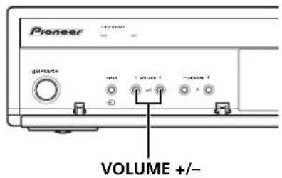
5 VOLUME +/- buttons
6 CHANNEL +/- buttons
7 PHONES output terminal
8 INPUT 4 terminal (S-VIDEO)
9 INPUT 4 terminal (VIDEO)
10 INPUT 4/PC INPUT terminals (AUDIO)
11 PC INPUT terminal (ANALOG RGB)
Rear view

text_image
1 2 3 4 5 6 7 8 IN OUT CONTROL SERVICE ONLY INPUT 3 INT-IN INPUT 2 USB WORKER B-AUDIO-1 B-AUDIO 3 R-VOC FOMIDE 7 COMPONENT VIDEO MONITOR OUT VIF: ETR-AUDIO-1 INPUT 1 AC-IN INPUT 3 BLOCK WITH 16 SYSTEM CABLE 19 20 21 221 CONTROL IN terminal
2 CONTROL OUT terminal
3 RS-232C terminal (used for factory setup)
4 INPUT 3 terminals (AUDIO)
5 INPUT 3 terminal (VIDEO)
6 INPUT 3 terminal (S-VIDEO)
7 MONITOR OUT terminals (AUDIO)
8 MONITOR OUT terminal (VIDEO)
9 ANT (Antenna) IN terminal
10 SUB WOOFER output terminal
11 INPUT 2 terminals (AUDIO)
12 INPUT 1 terminals (AUDIO)
13 INPUT 1 terminal (VIDEO)
14 INPUT 2 terminal (VIDEO)
15 INPUT 1 terminal (S-VIDEO)
16 INPUT 2 terminal (S-VIDEO)
17 INPUT 1 terminals
COMPONENT VIDEO: Y, CB/PB, CR/PR)
18 INPUT 2 terminals
COMPONENT VIDEO: Y, CB/PB, CR/PR)
19 INPUT 3 terminal (HDMI)
20 SYSTEM CABLE terminal (BLACK)
21 SYSTEM CABLE terminal (WHITE)
22 AC IN terminal
Remote control unit
text_image
1 2 3 4 5 6 7 8 9 10 11 12 13 14 15 PIONEER PLASMA DISPLAY INPUT 1 2 3 4 PC 1 2 3 4 5 6 7 8 9 0 + - P 1-2 - ENTER 8LE50X 20 21 22 23 24 25 261 ⏻
Turns on the power to the Plasma Display or places it into standby mode.
2 INPUT 1, 2, 3, 4
Selects an input source of the Plasma Display. (INPUT1, INPUT2, INPUT3, INPUT4).
3 PC
Selects the PC terminal as an input source.
4
Switches the screen mode among 2-screen, picture-in-picture, and single-screen.
50-9
Switches on the power to the Plasma Display.
TV/External input mode: Selects a channel.
TELETEXT mode: Selects a page.
6 CH RETURN
Returns to the previous channel.
7 P +/P -
TV/External input mode: Selects a channel.

TELETEXT mode: Selects a page.
8 I-II
Sets the sound multiplex mode.
9 ↩ (RETURN)
Restores the previous menu screen.
10 ///
Selects a desired item on the setting screen.
ENTER
Executes a command.
11 FRONT SURROUND
Switches the Front Surround mode.
12 Color (RED/GREEN/YELLOW/BLUE)
TELETEXT mode: Selects a page.
13
Freezes a frame from a moving image. Press again to cancel the function.

TELETEXT mode: Stops updating Teletext pages. Press again to release the hold mode.
14 ....
Jumps to the Teletext subtitle page.
15 ≡?
TELETEXT mode: Displays hidden characters.
16 i+
Displays the channel information.
17
Moves the location of the small screen when in the picture-in-picture mode.
18
Switches between the two screens when in the 2-screen or picture-in-picture mode.
19 CH ENTER
Executes a channel number.
20 ∠ +/ △ -
Sets the volume.
21
Mutes the sound.
22 HOME MENU
TV/External Input mode: Displays the Menu screen.
23 AV SELECTION
Selects audio and video settings. (AV mode: STANDARD, DYNAMIC, MOVIE, GAME, USER, PC mode: STANDARD, USER.)
24
TV/External input mode: Changes the wide screen size.

TELETEXT mode: Switches Teletext images. (full/upper half/lower half)
25
Selects the TELETEXT mode. (all TV image, all TEXT image, TV/TEXT image)
26 ≡i
TELETEXT mode: Displays an Index page for the CEEFAX/FLOF format. Displays a TOP Over View page for the TOP format.

NOTE
- When using the remote control unit, point it at the Plasma Display.
Installing the Plasma Display

text_image
Over 50 cm Over 10 cmLocation
- Avoid direct sunlight. Maintain adequate ventilation.
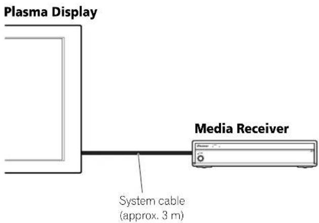
- The length of the system cable used to connect the Plasma Display and the Media Receiver is about 3 m.
- Because the Plasma Display is heavy, be sure to have someone help you when moving it.

CAUTION
- If you place anything on the top of the Media Receiver, it will not receive enough ventilation and will not operate properly.

NOTE
- Allow enough space around the upper and back parts when installing to ensure adequate ventilation of the rear of the unit.
Using the optional PIONEER stand
For details on installation, refer to the instruction manual supplied with the stand.
Using the optional PIONEER speakers
For details on installation, refer to the instruction manual supplied with the speaker.

CAUTION
Operating Environment
Operating environment temperature and humidity: +0 °C – +40 °C; less than 85 %RH (cooling vents not blocked) Do not install this unit in a poorly ventilated area, or in locations exposed to high humidity or direct sunlight (or strong artificial light)
Installing the Media Receiver
text_image
Plasma Display Media Receiver System cable (approx. 3 m)
CAUTION
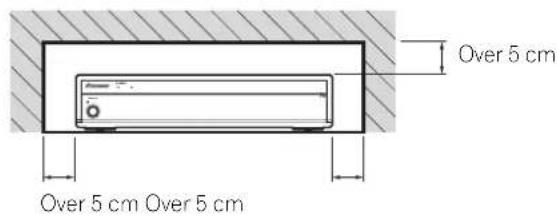
- Do not place a VCR or any other device on the top of the Media Receiver.
- When installing, allow enough space on the sides and above the Media Receiver.
- Do not block the side ventilation opening or the rear exhaust opening of the Media Receiver.
text_image
Over 5 cm Over 5 cm Over 5 cm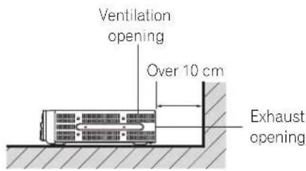
text_image
Ventilation opening Over 10 cm Exhaust opening
CAUTION
Placing the Media Receiver alone in the vertical position can result in product damage and malfunction.

natural_image
Pure electrical circuit lines without any symbolsPreventing the Plasma Display from Falling Over
After installing the stand, be sure to take special care to ensure that the Plasma Display will not fall over.
Stabilizing on a table or floor
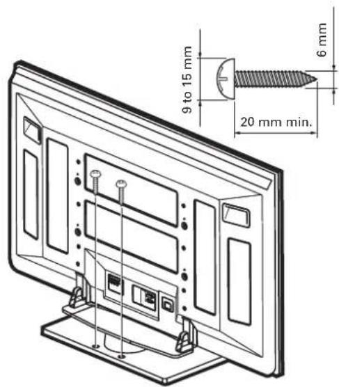
Stabilize the Plasma Display as shown in the diagram using screws that are available on the market.

NOTE
To stabilize the Plasma Display on a table or on the floor, use screws that have a nominal diameter of 6 mm and that are at least 20 mm long.
text_image
9 to 15 mm 20 mm min. 6 mm
CAUTION
A table or an area of the floor with adequate strength should always be used to support the Plasma Display. Failure to do so could result in personal injury and physical damage.
When installing the Plasma Display, please take the necessary safety measures to prevent it from falling or overturning in case of emergencies, such as earthquakes, or of accidents.
If you do not take these precautions, the Plasma Display could fall down and cause injury.
The screws, hooks, chains and other fittings that you use to secure the Plasma Display to prevent it from overturning will vary according to the composition and thickness of the surface to which it will be attached.
Select the appropriate screws, hooks, chains, and other fittings after first inspecting the surface carefully to determine its thickness and composition and after consulting a professional installer if necessary.
Using a wall for stabilization
-
Attach falling prevention bolts (hooks) to the Plasma Display.
-
Use strong cords or chains to stabilize it appropriately and firmly to a wall, pillar, or other sturdy element.
- Perform this work in the same way on the left and right sides.

NOTE
Use hooks, ropes, chains, and fittings that are available on the market.
Recommended hook: Nominal diameter 8 mm Length 12 to 15 mm

text_image
M8 12 to 15 mm ① Hook ② Cord or chain FittingConnecting the system cable
Connecting the system cable to the Plasma Display
Plasma Display (rear view)
text_image
(BLACK) (WHITE)For details on optional PIONEER speaker installation, refer to the instruction manual that came with the speaker.
Connecting the system cable to the Media Receiver
Media Receiver (rear view)

text_image
(BLACK) (WHITE)Routing cables
Speed clamps and bead bands are supplied for bunching cables. Once properly bunched, follow the steps below to route the cables.
When the speakers are installed on the sides (rear view)
text_image
Speaker cable Speed clamp Cable binder (supplied with the stand)* Speed clamp Speaker cableAttaching speed clamps to the main unit
Attach the speed clamps using the 2 holes marked with
↑ below, depending on your routing system.

natural_image
Technical line drawing of a mechanical component with mounting holes and a close-up inset showing a circular component (no text or symbols)Attaching and removing speed clamps
Insert [1] into an appropriate hole on the rear of the Plasma Display and snap [2] into the back of [1] to lock the clamp. Speed clamps are designed to be difficult to undo once in place. Please attach them carefully.
Use pliers to twist the clamp 90°, pulling outward. The clamp may deteriorate over time and become damaged if removed.

text_image
Diagram illustrating two mechanical or electrical setups with labeled components and directional arrowsWhen the speakers are installed at the bottom (PDP-436HDG only)

text_image
Speaker cable Cable binders (supplied with the stand)* Speaker cable
NOTE
- Use the supplied bead bands as necessary.
* Cable binder
Using the cable binders supplied with the stand, put the speaker and system cables together so that the cables are invisible from the front. At that time be careful not to apply any force to the connection sections of the cables.
Preparing the remote control unit
Inserting batteries
1 Open the battery cover.

2 Load the supplied two AA size batteries while inserting their respective negative polarity (−) ends first.

- Place batteries with their terminals corresponding to the (+) and (−) indicators in the battery compartment.
3 Close the battery cover.
Cautions regarding batteries
Improper use of batteries can result in chemical leakage or explosion. Be sure to follow the instructions below.
- When you replace the batteries, use manganese or alkaline ones.
- Place the batteries with their terminals corresponding to the (+) and (−) indicators.
- Do not mix batteries of different types. Different types of batteries have different characteristics.
- Do not mix old and new batteries. Mixing old and new batteries can shorten the life of new batteries or cause chemical leakage in old batteries.
- Remove batteries as soon as they have worn out. Chemicals that leak from batteries can cause a rash. If you find any chemical leakage, wipe thoroughly with a cloth.
- The batteries supplied with this product may have a shorter life expectancy due to storage conditions.
- If you will not use the remote control unit for an extended period of time, remove the batteries from it.

CAUTION
- WHEN DISPOSING OF USED BATTERIES, PLEASE COMPLY WITH GOVERNMENTAL REGULATIONS OR ENVIRONMENTAL PUBLIC INSTRUCTION'S RULES THAT APPLY IN YOUR COUNTRY/AREA.
Allowed operation range of the remote control unit
Operate the remote control unit while pointing it toward the remote control sensor (SR) located at the bottom right of the front panel of the Plasma Display. The distance from the remote control sensor must be within 7 m and the angle relative to the sensor must be within 30 degrees in the right, left, upward, or downward direction.

text_image
5 m 30° 7 m 30° Remote control sensorCautions regarding the remote control unit
- Do not expose the remote control unit to shock. In addition, do not expose the remote control unit to liquids, and do not place in an area with high humidity.
- Do not install or place the remote control unit under direct sunlight. The heat may cause deformation of the unit.
- The remote control unit may not work properly if the remote control sensor of the Plasma Display is under direct sunlight or strong lighting. In such case, change the angle of the lighting or Plasma Display, or operate the remote control unit closer to the remote control sensor.
- When any obstacle exists between the remote control unit and the remote control sensor, the remote control unit may not function.
- As the batteries become empty, the remote control unit can function within a shorter distance from the remote control sensor. Replace the batteries with new ones early enough.
- The Plasma Display emits very weak infrared rays from its screen. If you place such equipment operated through infrared remote control as a VCR nearby, that equipment may not receive commands from its remote control unit properly or entirely. If this is the case, place that equipment at a location far enough from the Plasma Display.
- Depending on the installation environment, infrared rays from the Plasma Display may not allow this system to properly receive commands from the remote control unit or may shorten allowable distances between the remote control unit and the remote control sensor. The strength of infrared rays emitted from the screen differs, depending on images displayed on the screen.
Connecting to an antenna
To enjoy a clearer picture, use an outdoor antenna. The following is a brief explanation of the types of connections that are used for a coaxial cable.

text_image
Connect the 75-ohm coaxial cable (commercially available) to the ANT (ANT IN) terminal.Antenna cable (commercially available)
If your outdoor antenna uses a 75-ohm coaxial cable with a standard DIN45325 plug (IEC169-2), plug it into the ANT IN terminal at the rear of the Media Receiver.
Connecting the power cord
Plasma Display (rear view)
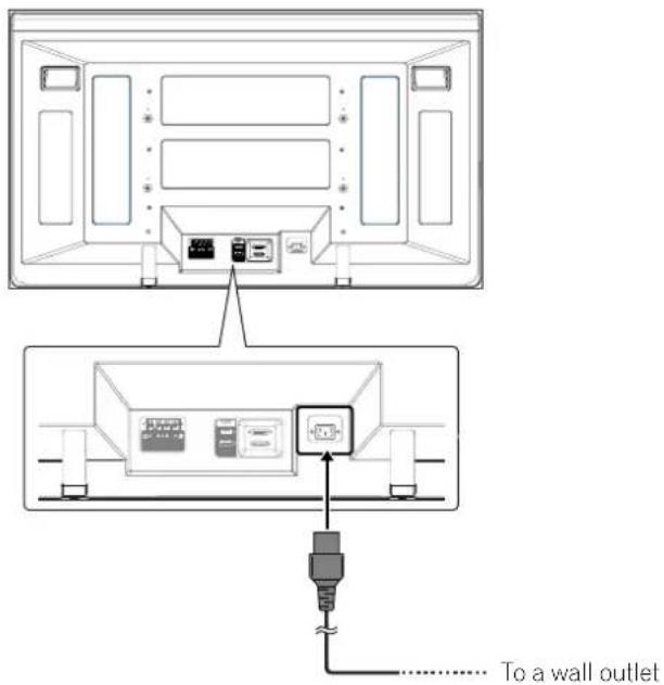
text_image
To a wall outletAttaching the territe core
To help prevent noise, attach the supplied ferrite core to the connector end of the power cord as shown. Use the supplied cable tie to prevent the ferrite core from slipping on the cable.
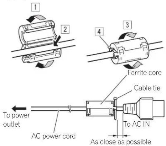
text_image
1 2 3 4 Ferrite core Cable tie To power outlet AC power cord As close as possible To AC INMedia Receiver (rear view)
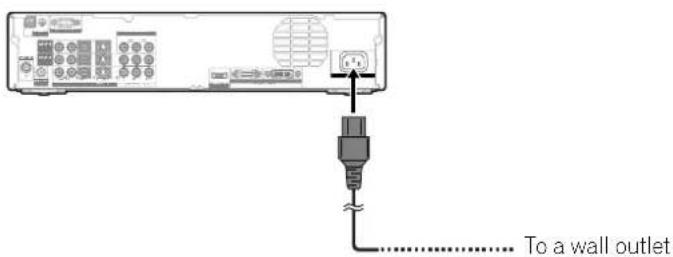
text_image
To a wall outlet
NOTE
- Disconnect the power cord from the power outlet, Plasma Display and Media Receiver when the system is not going to be used for a long period of time.
Unless you set up TV channels that you can watch under the current conditions, you cannot tune in those channels. For the procedure, see "Setting up TV channels automatically" on page 27.
Turning on/ off the power

NOTE
- When the Media Receiver is plugged into a power outlet, it is placed into the standby mode; the STANDBY indicator on its front panel should flash red. The Media Receiver stays in the standby mode unless it is unplugged from the power outlet.
To turn on the system, press POWER on the Plasma Display.
- The POWER ON indicators on the Plasma Display and Media Receiver light up in blue.
To turn off the system, press ⏻ on the remote control unit or STANDBY/ON on the Media Receiver.
- The Plasma Display and Media Receiver are placed into the standby mode; their respective STANDBY indicators light up in red.
- You can then turn on the system again by pressing ⏻ or 0 to 9 on the remote control unit or STANDBY/ON on the Media Receiver. If you press 0 on the remote control unit, images come from the INPUT 1 source. If you press 1 to 9, TV images display.
You can also press POWER on the Plasma Display to turn off the system. However, you cannot then turn on the system again by pressing the buttons on the remote control unit and Media Receiver.

NOTE
- If you are not going to use the Plasma Display System for a long period of time, be sure to remove the power cord from the power outlet.
- When the system is placed into the standby mode, the main power flow is cut and the system is no longer fully operational. A minute flow of power feeds the system to maintain operation readiness.
Plasma Display/Media Receiver status indicators
The table below shows the operational status of the Plasma Display System. You can check the current status of the system with the indicators on the Plasma Display and Media Receiver.
Plasma Display

text_image
POWER ON indicator STANDBY indicatorPOWER button
Media Receiver
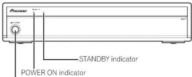
text_image
Pioneer STANDBY indicator POWER ON indicatorSTANDBY/ON button

text_image
INPUT 1 2 3 4 PC 1 2 4 5 7 8 0 24 R1111 R1112Indicator Status System Status
| Plasma Display | Media Receiver | |||
| POWER ON | STANDBY | POWER ON | STANDBY | |
| ● | ● | ● | ● | The power cords of both the Plasma Display and the Media Receiver have been disconnected. Or, the power cord of the Plasma Display has been connected but the POWER button of the Plasma Display is off. |
| [KS5X] | [ASDS] |  |  | Power to the system is on. |
| ● | [K208] | ● |  | The system is in the standby mode. |
| ● | [WZTO]Flashing | ● | [4490] | The power cord of the Media Receiver has been disconnected. |
| ● | ● | ● | [5460]Flashing | Power to the Plasma Display is off. Or the power cord of the Plasma Display has been disconnected. |
Flashing
For other than the above, see "Troubleshooting" on page 50.
Media Receiver (front view)

text_image
Pioneer OFF/24/01 OUTLINE + / + / - / - CHANNEL +/-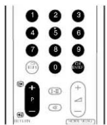
text_image
1 2 3 4 5 6 7 8 9 0 + I-E + - + - RETURNChannel display

text_image
8 AAA STEREO 10:00 STANDARD FULLMedia Receiver (front view)
text_image
Pioneer VOLUME +/-
Volume adjustment

text_image
28Muting

text_image
OK 28Changing channels
Using P +/P - on the remote control unit
- Press P + to increase the channel number.
- Press P – to decrease the channel number.
When viewing Teletext information:
- Press P + to increase the page number.
- Press P - to decrease the page number.
For Teletext, see "Using the Teletext Functions" on pages 42 and 43.

NOTE
- CHANNEL +/- on the Media Receiver operates the same as P +/P -.
- P +/P – cannot pick up channels that are set to skip. For Channel Skip, see steps 13 and 14 under "Using Manual Adjust" (page 28).
Using 0 - 9 on the remote control unit
Select channels directly by pressing buttons 0 to 9.
EXAMPLE
• To select channel 2 (1-digit channel), press 2.
• To select channel 12 (2-digit channel), press 1 then 2.
When viewing Teletext information:
View a page directly which is 3-digit page number from 100 to 899 by pressing buttons 0 to 9. See page 42.

NOTE
• After entering a channel or subchannel number, you may press CH ENTER to tune in the channel more quickly.
- In the standby mode, when you press 0, the power turns on and images come from the INPUT 1 source. Or, when you press any button from 1 to 9, TV images display.
Changing the volume and sound
Using + / - on the remote control unit
• To increase the volume, press ∠+
• To decrease the volume, press △-

NOTE
• VOLUME +/- on the Media Receiver operates the same as ∠+/△−.
Using ☒ on the remote control unit
mutes the current sound output.
1 Press 咬.
- “呫” appears on the screen.
2 Press ☒ again to cancel the mute mode.
- Pressing + also cancels the mute mode.
Using I-II on the remote control unit
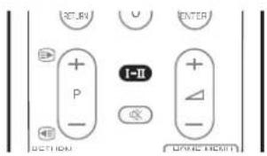
text_image
SETURN U ENTER + I-II P - - ACTION ON/OFF/RETURN ON/OFF/RETURNEach time you press I-II, MTS toggles as shown below.
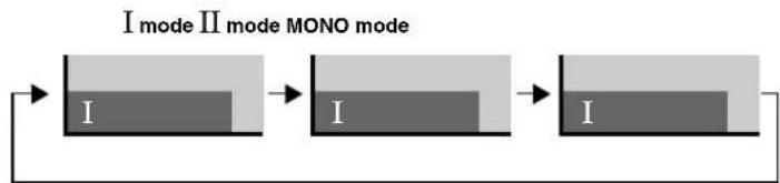
flowchart
graph LR
    A["I mode II mode MONO mode"] --> B["I mode"]
    B --> C["I mode"]
| Setting | ||||
| I | II | MONO | ||
| NICAM Broadcasts | Stereo | 1AAA NICAM STEREO | 1AAA NICAM STEREO | 1AAA MONO |
| Bilingual | 2BBB NICAM I | 2BBB NICAM II | 2BBB MONO | |
| Monaural | 3CCC NICAM MONO | 3CCC NICAM MONO | 3CCC MONO | |
| A2 Broadcasts | Stereo | 4DDD STEREO | 4DDD STEREO | 4DDD MONO |
| Bilingual | 5EEE DUAL I | 5EEE DUAL II | 5EEE MONO | |
| Monaural | 6FFF MONO | 6FFF MONO | 6FFF MONO | |
| BTSC Broadcasts | Stereo | 4GGG STEREO | 4GGG STEREO | 4GGG MONO |
| MAIN+SAP | 5HHH MONO(SAP) | 5HHH SAP(MAIN) | 5HHH MONO | |
| Stereo+SAP | 5JJJ STEREO(SAP) | 5JJJ SAP(STEREO) | 5JJJ MONO | |
| Monaural | 6KKK MONO | 6KKK MAIN | 6KKK MONO | |

NOTE
- In each of the sound multiplex mode selected using the I-II button, the display changes depending on broadcasting signals being received.
-
Once the MONO mode is selected, the Plasma Display System sound remains mono even if the system receives a stereo broadcast. You must switch the mode back to I or II mode if you want to hear stereo sound again.
-
Selecting a sound multiplex mode while the input source is INPUT 1 to 4 or PC does not change the type of sound. In this case, sound is determined by the video source.
- While watching a TV channel with any High Deviation setting (page 29), you cannot change the sound multiplex mode.
Using the multiscreen functions
Splitting the screen
Use the following procedure to select the 2-screen or picture-in-picture mode.
2-screen
natural_image
Black-and-white photo showing a house on the left and a sailboat on the right, both with mountain background (no text or symbols)Picture-in-picture

text_image
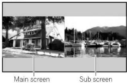
Main screen Sub screen
text_image
PC 1 2 3 4 5 6 7 8 9 CH RETURN P I-II CH ENTER HOME MENU ENTER FRONT SURROUND AV SELECTION1 Press ☐ to select the display mode.
• Each time you press ☐, the display mode is switched among 2-screen, picture-in-picture, and single-screen.
- In 2-screen or picture-in-picture mode, press switch the position of the 2 screens shown. The left screen (in the 2-screen mode) or the larger screen (in the picture-in-picture mode) is the active screen which will be indicated by "♪". The user is allowed to operate picture and sound.

natural_image
Side-by-side comparison of a lakeside scene with buildings and trees, showing structural changes (no text or symbols)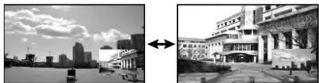
natural_image
Split black-and-white photo showing a city skyline on the left and a building with a large entrance on the right, both connected by an arrow (no visible text or symbols)- In 2-screen mode, press 📋 to change the size of the left screen.
- In picture-in-picture mode, press 📋 move the position of the small screen anti-clockwise.
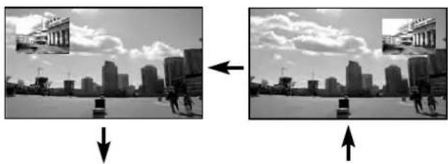
natural_image
Two black-and-white photos showing urban buildings with cityscapes and a cloudy sky, each with an arrow indicating direction of change (no text or symbols)
natural_image
Side-by-side comparison of a cityscape under cloudy skies, showing before-and-after transformation with arrow (no text or symbols)2 To select the desired input source, press the appropriate input source button.
- If watching TV programs, press P +/P - to change the channel.

NOTE
- The multiscreen function cannot display images from the same input source at the same time. If you make such an attempt, a warning message appears.
- When you press HOME MENU, the single-screen mode is restored and the corresponding menu is displayed.
- When in the 2-screen mode, images displayed on the right screen may look less fine, depending on images.
- If you select 1920*1080p@24Hz for the main screen in the picture-in-picture mode, video images may not be displayed properly because of the system's capability.
- With headphones connected, you can listen to audio coming from the sub screen when in the 2-screen or picture-in-picture mode. For more information, see page 36.
Freezing images
Use the following procedure to capture and freeze one frame from a moving image that you are watching.
1 Press
- A still image appears on the right screen while a moving image is shown on the left screen.
2 Press 📄 again to cancel the function.
text_image
RETURN HOME MENU ENTER FRONT SURROUND AV SELECTION
text_image
Normal image Still imageNOTE
- With the screen split, any image cannot be frozen.
- When this function is not available, a warning message appears.
Menu Configuration
AV mode menus
| Home Menu Item Page | ||
| Picture AV Selection 31 | ||
| Contrast 32 | ||
| Brightness 32 | ||
| Color 32 | ||
| Tint 32 | ||
| Sharpness 32 | ||
| Pro Adjust 32 – 35 | ||
| Reset | 32 | |
| Sound | Treble | 35 |
| Bass | 35 | |
| Balance | 35 | |
| Reset | 35 | |
| FOCUS 35, 36 | ||
| Front Surround | 36 | |
| Headphone Output | 36 | |
| Sub Volume | 36 |
| Power Control | Energy Save | 37 |
| No Signal off | 37 | |
| No Operation off | 37 |
| Sleep Timer | — | 40 |
| Option | Position | 38 |
| Auto Size | 40 | |
| 4:3 Mode | 40 | |
| Side Mask 40 | ||
| HDMI Input | 47 | |
| Drive Mode | 38 | |
| Color System | 39 | |
| Monitor Out | 47 |
| Setup | Auto Installation | 27 |
| Program Setup | 27 – 30 | |
| Password | 41 | |
| Language | 31 |
PC mode menus
| Home Menu Item Page | ||
| Picture AV Selection 31 | ||
| Contrast 32 | ||
| Brightness 32 | ||
| Red | 32 | |
| Green | 32 | |
| Blue | 32 | |
| Reset | 32 | |
| Sound | Treble | 35 |
| Bass | 35 | |
| Balance | 35 | |
| Reset | 35 | |
| FOCUS 35, 36 | ||
| Front Surround | 36 | |
| Headphone Output | 36 | |
| Sub Volume | 36 |
| Power Control | Energy Save | 37 |
| Power Management | 37 |
| Sleep Timer | —— | 40 |
| Option | Auto Setup | 38 |
| Manual Setup | 38 |
Menu operations
The following describes the typical procedure for setting up the menus. For the actual procedures, see the appropriate pages that describe individual functions.

1 Press HOME MENU.
2 Press ↑/↓ to select a menu item, and then press ENTER.
3 Repeat step 2 until you access the desired submenu item.
- The number of menu layers differs depending on the menu items.
4 Press to select an option (or parameter), and then press ENTER.
- For some menu items, press instead of /.
5 Press HOME MENU to exit the menu.

NOTE
- You can return to the upper menu levels by pressing RETURN.
Setting up TV channels automatically
This section describes how to automatically search for and set up TV channels.
Using Auto Installation
When the Plasma Display System is switched on for the first time after purchase, the initial auto installation is initiated. You can automatically set language, country and channels in successive operations.
1 Select "Language" (/)↑↓
2 Select a language (/)
text_image
Auto Installation Language English Channel Allocation Cable (US Type) Installation Start- You can select from among five languages; English, Spanish, Portuguese, Traditional chinese and Simplified chinese.
3 Select "Channel Allocation" (/)
4 Select "Normal", "Air (US Type)", or "Cable (US Type)" (/←→).
- The table in page 51 shows which option you should usually select in your country or region.
Item Description
| Normal Scans to locate your regional broadcasting frequencies. The earlier the frequencies identified, the smaller the channel numbers used. |
| Air (US Type) Searches for the same broadcasting frequencies as for receiving over air in the U.S. This selection is effective when the system is receiving over air. |
| Cable (US Type) | Searches for the same broadcasting frequencies as for watching cable TV in the U.S. This selection is effective when the system is receiving from a cable TV company. |
5 Select "Start" (↑/↓ then ENTER).
• Auto Installation automatically starts.
- To quit Auto Installation in progress, press RETURN.
6 After Auto Installation has been finished, press HOME MENU to exit the menu.
NOTE
- You can start Auto Installation from the Home menu after moving to another country, for example. Perform the following steps ① to ③ before starting Auto Installation.
① Press HOME MENU.
② Select "Setup" (↑/↓ then ENTER).
③ Select "Auto Installation" (↑/↓ then ENTER).
- The password entry screen appears. Enter your 4-digit password using buttons 0 - 9.
- If no channel is found, check the antenna connections, and then retry Auto Installation.
Using Auto Search
Auto Search allows you to select a region and set up TV channels with the system specific to the selected region.
1 Press HOME MENU.
2 Select "Setup" (▲/↓ then ENTER).
3 Select "Program Setup" (↑/↓ then ENTER).
- The password entry screen appears. Enter your 4-digit password using buttons 0 - 9.
4 Select "Auto Search" (↑/↓ then ENTER).
5 Select "Region" (/)↑↓
6 Select the region (/)←→
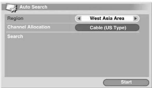
text_image
Auto Search Region West Asia Area Channel Allocation Cable (US Type) Search Start7 Select "Channel Allocation" (/)↑↓
8 Select "Normal", "Air (US Type)", or "Cable (US Type)" (/←→).
- The table in page 51 shows which option you should usually select in your country or region.
Item Description
| Normal Scans to locate your regional broadcasting frequencies. The earlier the frequencies identified, the smaller the channel numbers used. | |
| Air (US Type) | Searches for the same broadcasting frequencies as for receiving over air in the U.S. This selection is effective when the system is receiving over air. |
| Cable (US Type) | Searches for the same broadcasting frequencies as for watching cable TV in the U.S. This selection is effective when the system is receiving from a cable TV company. |
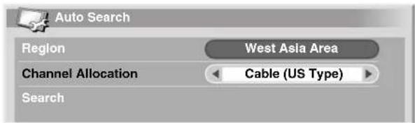
text_image
Auto Search Region West Asia Area Channel Allocation Cable (US Type) Search9 Select "Start" (↑/↓ then ENTER).
• Channel search automatically starts.
• To quit channel search in progress, press RETURN.
10 Press HOME MENU to exit the menu.

NOTE
- If no channel is found, check the antenna connections, and then retry Auto Search.
Setting up TV channels manually
This section describes how to set up TV channels manually.
Using Manual Adjust
Use Manual Adjust to set up TV channels manually. Steps 5 to 14 differ depending on your selection for Channel Allocation.
1 Press HOME MENU.
2 Select "Setup" (↑/↓ then ENTER).
3 Select "Program Setup" (↑/↓ then ENTER).
- The password entry screen appears. Enter your 4-digit password using buttons 0 - 9. For the password, see "Using a password" on page 41.
4 Select "Manual Adjust" (↑/↓ then ENTER).
5 Select "Program Entry" (/)↑↓
6 Select a program number (/)
- With "Normal" selected, you can select 1 through 99.
- With "Air (US Type)" selected, you can select 2 through 69.
- With "Cable (US Type)" selected, you can select 1 through 125.
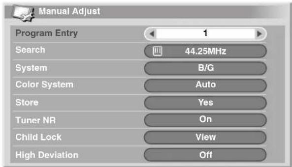
text_image
Manual Adjust Program Entry 1 Search 44.25MHz System B/G Color System Auto Store Yes Tuner NR On Child Lock View High Deviation Off7 Select "Search" (/)↑↓
8 Enter a frequency (0 - 9 then ENTER).
- You can also press to enter a frequency.
- With "Air (US Type)" or "Cable (US Type)" selected, you cannot change the displayed frequency.

text_image
Program Entry Search 44.25MHz System B/G9 Select "System" (/)↑↓
10 Select a sound system (◀)→
- You can select from among "B/G", "D/K", "I", "M", and "N".
- With "Air (US Type)" or "Cable (US Type)" selected, you cannot change from the factory default (M).

text_image
Search 44.25MHz System B/G Color System Auto11 Select "Color System" (▲, ↓)
12 Select a color system (◀).
- You can select from among "Auto", "PAL", "NTSC", "SECAM", "PAL-M", "PAL-N", and "4.43NTSC".
- With "Air (US Type)" or "Cable (US Type)" selected, you cannot change from the factory default (Auto).

text_image
System B/G Color System Auto Store Yes13 Select "Store" (▲).↓
14 Select "Yes" (◀).→
- With "Air (US Type)" or "Cable (US Type)" selected, press //to select "ADD/DEL", and then press //select "ADD".

text_image
Color System Store Tuner NR Auto Yes On- With "Yes" selected, you can select the channel using P +/P-. With "No" selected, you cannot select the channel using P +/P-.
• To set up for another channel, repeat steps 5 to 14.
15 Press HOME MENU to exit the menu.

NOTE
- Manual Adjust also allows you to make selections for "Tuner NR", "Child Lock", and "High Deviation". See "Reducing video noise", "Setting Child Lock", and "Suppressing audio distortion" respectively.
- This Plasma Display System is equipped with the auto frequency tuning function that automatically adjusts tuning frequencies according to received signals. For this reason, the Manual Adjust menu may show slightly different frequencies from your entry when you access the menu next time. You cannot deactivate the auto frequency tuning function.
Reducing video noise
For the individual channels, you can specify whether the Plasma Display System should reduce video noise depending on the levels of broadcasting signals.
1 Press HOME MENU.
2 Select "Setup" ( / then ENTER).
3 Select "Program Setup" (↑/↓ then ENTER).
- The password entry screen appears. Enter your 4-digit password using buttons 0 - 9. For the password, see "Using a password" on page 41.
4 Select "Manual Adjust" (↑/↓ then ENTER).
5 Select "Program Entry" (/)↑↓

text_image
Manual Adjust Program Entry 1 Search 44.25MHz6 Select a program number (/)
- You can select 1 through 99 with "Normal" selected, 2 through 69 with "Air (US Type)" selected, or 1 through 125 with "Cable (US Type)" selected.
7 Select "Tuner NR" (/)↑↓
8 Select "On" or "Off" (/)←→

text_image
Store Yes Tuner NR On Child Lock View9 Press HOME MENU to exit the menu.

NOTE
- This function may not achieve a satisfactory result, depending on the conditions of broadcasting signals.
Setting Child Lock
Child Lock inhibits selected TV channels from being tuned and watched.
1 Press HOME MENU.
2 Select "Setup" (▲/▼ then ENTER).
3 Select "Program Setup" (↑/↓ then ENTER).
- The password entry screen appears. Enter your 4-digit password using buttons 0 - 9. For the password, see "Using a password" on page 41.
4 Select "Manual Adjust" (↑/↓ then ENTER).
5 Select "Program Entry" (/)↑↓

text_image
Manual Adjust Program Entry 1 Search 44.25MHz6 Select a program number (/)←→
- You can select 1 through 99 with "Normal" selected, 2 through 69 with "Air (US Type)" selected, or 1 through 125 with "Cable (US Type)" selected.
7 Select "Child Lock" (/)
8 Select "Block" (/)←→

text_image
Tuner NR Child Lock Block High Deviation On Off- The selection is switched between "View" and "Block".
9 Press HOME MENU to exit the menu.
Suppressing audio distortion
You can suppress audio distortion that may be induced when too strong audio signals are received in the selected channel.

NOTE
- High Deviation is selectable only when you have selected "D/K" for "System" under "Using Manual Adjust" (page 28).
1 Press HOME MENU.
2 Select "Setup" (↑/↓ then ENTER).
3 Select "Program Setup" (↑/↓ then ENTER).
- The password entry screen appears. Enter your 4-digit password using buttons 0 - 9. For the password, see "Using a password" on page 41.
4 Select "Manual Adjust" (↑/↓ then ENTER).
5 Select "Program Entry" (/)↑↓

text_image
Manual Adjust Program Entry 1 Search 44.25MHz6 Select a program number (/)
- You can select 1 through 99 with "Normal" selected, 2 through 69 with "Air (US Type)" selected, or 1 through 125 with "Cable (US Type)" selected.
7 Select "High Deviation" (/)↑↓
8 Select "Off", "High", "Mid", or "Low" (/)

text_image
Tuner NR On Child Lock View High Deviation OffItem Description
Off Deactivates the function. (factory default)
High Suppresses audio distortion slightly; however, the audio volume is slightly lowered than when Off is selected.
Mid Suppresses audio distortion moderately.
Low Suppresses audio distortion further; however, the audio volume is further lowered.
9 Press HOME MENU to ext the menu.

NOTE
- While watching a TV channel with any High Deviation setting, you cannot change the sound multiplex mode.
Labeling TV channels
You can name TV channels that you have set up, using up to five characters. This may help you easily identify the channels during selections.
1 Press HOME MENU.
2 Select "Setup" ( / then ENTER).
3 Select "Program Setup" (↑/↓ then ENTER).
- The password entry screen appears. Enter your 4-digit password using buttons 0 - 9.
4 Select "Label" (↑/↓ then ENTER).
5 Select "Program Entry" (/)↑↓
6 Select a program number (/)
- You can select 1 through 99 with "Normal" selected, 2 through 69 with "Air (US Type)" selected, or 1 through 125 with "Cable (US Type)" selected.

text_image
Label Program Entry 1 Label7 Select "Label" (▲/▼ then ENTER).
• The name entry screen appears.
8 Select the first character ( / , / then ENTER).
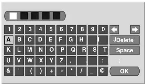
text_image
1 2 3 4 5 6 7 8 9 0 A B C D E F G H K L M N O P Q R S T U V W X Y Z , . : : & ' ( ) + - * / _ @ JDelete Space ; OK- The cursor moves to the second character.
9 Repeat step 8 to enter up to five characters.
- To correct entered characters, select or [] on the screen, and then press ENTER. The cursor moves to the preceding or subsequent character.
- To delete the current character, select [Delete] on the screen, and then press ENTER.
- To put a space for the current character, select [Space] on the screen, and then press ENTER.
10 To complete the name entry, press ▲▼/ to select [OK] on the screen, and then press ENTER.
11 Press HOME MENU to exit the menu.

NOTE
- The above procedure transfers and sets the selected channel information to the connected recording equipment such as a VCR or DVD recorder.
Sorting preset TV channels
Use the following procedure to change the sequence of the preset TV programs.
1 Press HOME MENU.
2 Select "Setup" ( / then ENTER).
3 Select "Program Setup" (↑/↓ then ENTER).
- The password entry screen appears. Enter your 4-digit password using buttons 0 - 9.
4 Select "Sort" ( / then ENTER).
• The sort screen appears.
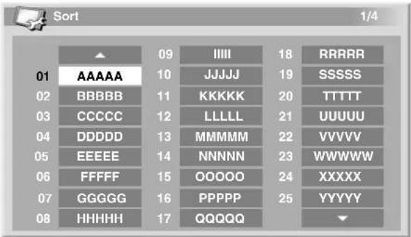
text_image
Sort 1/4 01 AAAAA 02 BBBBB 03 CCCCC 04 DDDDD 05 EEEEE 06 FFFFF 07 GGGGG 08 HHHHH 09 IEEE 10 JJJJJ 11 KKKKK 12 LLLLL 13 MMMMM 14 NNNNN 15 OOOOO 16 PPPPP 17 QQQQQ 18 RRRRR 19 SSSSS 20 TTTTT 21 UUUUU 22 VVVVV 23 WWWWW 24 XXXXX 25 YYYYY ▼5 Select a channel to be shifted ( / , / then ENTER).
6 Select a new location (↑/↓, ←/→ then ENTER).
- Sorting is executed.
7 Press HOME MENU to exit the menu.

NOTE
- To change a page on the Sort screen in step 6, select ▲/▼ on the screen with ↑ to select a page, and then press ENTER.
- The above procedure transfers and sets only the shifted channel information to recording equipment such as a VCR or DVD recorder.
Language setting
You can select the language to be used for on-screen display such as menus and instructions, from among five languages; English, Spanish, Portuguese, Traditional chinese and Simplified chinese.
For the language to be used in the TELETEXT mode, you can select from among West Europe, East Europe, Greece/Turkey, Russia, and Arabia.
1 Press HOME MENU.
2 Select "Setup" (↑/↓ then ENTER).
3 Select "Language" (↑/↓ then ENTER).
4 Select "Menu" (/)↑↓
5 Select a language (/)

text_image
Language Menu English Teletext West Europe6 Select "Teletext" (/)↑ ↓
7 Select a language (/)
8 Press HOME MENU to exit the menu.
AV Selection
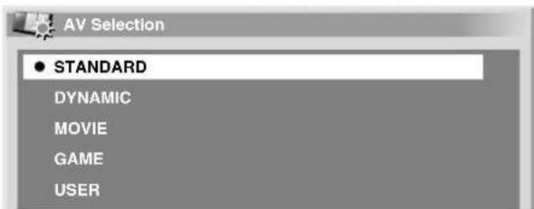
Select from the five viewing options, depending on the current environment (e.g., room brightness), the type of the current TV program, or the type of images input from external equipment.
1 Press HOME MENU.
2 Select "Picture" (↑/↓ then ENTER).
3 Select "AV Selection" (↑/↓ then ENTER).
4 Select the desired option ( / then ENTER).
text_image
AV Selection ● STANDARD DYNAMIC MOVIE GAME USERFor AV source
| Item Description | |
| STANDARD | For a highly defined image in a normally bright roomThis selection is shared by an external input and TV input sources. |
| DYNAMIC For a very sharp image with the maximum contrastThis mode does not allow manual image quality adjustment.This selection is shared by an external input and TV input sources. | |
| MOVIE For a movie | This selection is shared by an external input and TV input sources. |
| GAME Lowers image brightness for easier viewingThis selection is shared by an external input and TV input sources. | |
| USER Allows the user to customize settings as desired. You can set the mode for each input source. | |
For PC source
| Item Description | |
| STANDARD | For a highly defined image in a normally bright room |
| USER Allows the user to customize settings as desired. You can set the mode for each input source. | |
5 Press HOME MENU to exit the menu.
NOTE
- You can also press AV SELECTION on the remote control unit to switch the viewing option.
- If you have selected "DYNAMIC", you cannot select "Contrast", "Brightness", "Color", "Tint", "Sharpness", "Pro Adjust", and "Reset"; these menu items are dimmed.
Basic picture adjustments
Adjust the picture to your preference for the chosen AV Selection option (except DYNAMIC).
1 Press HOME MENU.
2 Select "Picture" (♠/↓ then ENTER).
3 Select an item to be adjusted ( / then ENTER).

text_image
Picture AV Selection STANDARD Contrast 40 Brightness 0 Color 0 Tint 0 Sharpness 0 Pro Adjust Reset4 Select the desired level (/)

text_image
Contrast 40- When an adjustment screen is in display, you can also change the item to be adjusted, by pressing ↑.↓
5 Press HOME MENU to exit the menu.
For AV source
| Item | ← button button | → |
| Contrast For less contrast For more contrast | ||
| Brightness For less brightness For more brightness | ||
| Color For less color intensity For more color intensity | ||
| Tint Skin tones become purplish | Skin tones become greenish | |
| Sharpness For less sharpness For more sharpness | ||
For PC source
| Item | ← button button | → |
| Contrast For less contrast For more contrast | ||
| Brightness For less brightness For more brightness | ||
| Red For weaker red | For stronger red | |
| Green | For weaker green | For stronger green |
| Blue | For weaker blue | For stronger blue |
For PC source, the following screen appears:
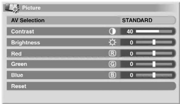
text_image
Picture AV Selection STANDARD Contrast 40 Brightness 0 Red R 0 Green G 0 Blue B 0 Reset
NOTE
- To perform advanced picture adjustments, select "Pro Adjust" in step 3 and then press ENTER. For the subsequent procedures see "Advanced picture adjustment" on page 33.
- To restore the factory defaults for all items, press ⚠ to select "Reset" in step 3, and then press ENTER. A confirmation screen appears. Press ⚠ to select "Yes", and then press ENTER.
Advanced picture adjustments
The Plasma Display System provides various advanced functions for optimizing the picture quality. For details on these functions, see the tables.
Using PureCinema
1 Press HOME MENU.
2 Select "Picture" (▲/▼ then ENTER).
3 Select "Pro Adjust" (↑/↓ then ENTER).
4 Select "PureCinema" (▲/▼ then ENTER).
5 Select the desired parameter ( / then ENTER).
- For the selectable parameters, see the table.
PureCinema
Automatically detects a film-based source (originally encoded at 24 frames/second), analyses it, then recreates each still film frame for high-definition picture quality.
Selections Off Deactivates the PureCinema.
Standard Produces smooth and vivid moving images (film specific) by automatically detecting recorded image information when displaying DVD or high-definition images (e.g., movies) having 24 frames per second.
ADV Produces smooth and quality moving images (as shown on theatre screens) by converting to 72 Hz when displaying DVD images (e.g., movies) having 24 frames per second.

NOTE
- "Standard" is not selectable when 480p or 720p@60Hz signals are input.
- "ADV" is not selectable when PAL, SECAM, 576i, or 1080i@50Hz signals are input.
- Neither "Standard" nor "ADV" is selectable when 576p, 720p@50Hz, or 1080p@24Hz signals are input.
Using Color Temp
1 Press HOME MENU.
2 Select "Picture" (▲/↓ then ENTER).
3 Select "Pro Adjust" ( / then ENTER).
4 Select "Color Detail" (↑/↓ then ENTER).
5 Select "Color Temp" (▲/↓ then ENTER).
6 Select the desired parameter ( / then ENTER).
- If you have selected a desired parameter in this step, skip steps 7 and 8.
- You may rather want to perform fine adjustment. To do this, select "Manual" first and then press and hold ENTER for more than three seconds. The manual adjustment screen appears. Then go to step 7.
Color Temp
Adjusts the color temperature, resulting in a better while balance.
Selections High White with bluish tone
Mid-High Intermediate tone between High and Mid
Mid Natural tone
Mid-Low Intermediate tone between Mid and Low
Low White with reddish tone
Manual Color temperature adjusted to your preference
7 Select an item to be adjusted ( / then ENTER).
8 Select the desired level (/)
| Item | ← button | → button | |
| R High | Fine adjustment for bright portions | For weaker red | For stronger red |
| G High | For weaker green For stronger green | ||
| B High | For weaker blue | For stronger blue | |
| R Low | Fine adjustment for dark portions | For weaker red | For stronger red |
| G Low | For weaker green For stronger green | ||
| B Low | For weaker blue | For stronger blue | |
- To perform adjustment for another item, press RETURN, and then repeat steps 7 and 8.
- You may press to immediately change an item to be adjusted.
9 Press HOME MENU to exit the menu.
Using CTI
1 Press HOME MENU.
2 Select "Picture" ( / then ENTER).
3 Select "Pro Adjust" (▲/▼ then ENTER).
4 Select "Color Detail" (↑/↓ then ENTER).
5 Select "CTI" (▲/↓ then ENTER).
6 Select the desired parameter ( / then ENTER).
CTI
Provides images with clearer color contours. The CTI stands for Color Transient Improvement.
Selections Off Deactivates the CTI.
On Activates the CTI.
7 Press HOME MENU to exit the menu.
Using Color Management
1 Press HOME MENU.
2 Select "Picture" (▲/▼ then ENTER).
3 Select "Pro Adjust" ( / then ENTER).
4 Select "Color Detail" (↑/↓ then ENTER).
5 Select "Color Management" ( / then ENTER).
6 Select an item to be adjusted ( / then ENTER).

text_image
Color Management R 0 Y 0 G 0 C 0 B 0 M 07 Select the desired level (/)
| Item | ← button button | → |
| R Closer to magenta Closer to yellow | ||
| Y Closer to red Closer to green | ||
| G Closer to yellow Closer to cyan | ||
| C Closer to green Closer to blue | ||
| B Closer to cyan | Closer to magenta | |
| M | Closer to blue | Closer to red |
- To perform adjustment for another item, press RETURN, and then repeat steps 6 and 7.
- You may press immediately change an item to be adjusted.
8 Press HOME MENU to exit the menu.
Eliminating noise from images
1 Press HOME MENU.
2 Select "Picture" (↑/↓ then ENTER).
3 Select "Pro Adjust" ( / then ENTER).
4 Select "NR" (/ male ENTER).
5 Select an item to be adjusted ( / then ENTER).
• You can select "DNR" or "MPEG NR".
6 Select the desired parameter ( / then ENTER).
DNR
Eliminates video noise for clean crisp images. The DNR stands for Digital Noise Reduction.
Selections Off Deactivates the DNR.
| High | Enhanced DNR |
| Mid | Standard DNR |
| Low | Moderate DNR |
MPEG NR
Eliminates mosquito noise from video images when a DVD is played, resulting in noise-free images.
Selections Off Deactivates the MPEG NR.
| High | Enhanced MPEG NR |
| Mid | Standard MPEG NR |
| Low | Moderate MPEG NR |
7 Press HOME MENU to exit the menu.
Using the Dynamic Range Expander (DRE) functions
1 Press HOME MENU.
2 Select "Picture" (↑/↓ then ENTER).
3 Select "Pro Adjust" ( / then ENTER).
4 Select "DRE" (↑/↓ then ENTER).
5 Select an item to be adjusted ( / then ENTER).
- You can select "Dynamic Contrast", "Black Level", "ACL" or "Gamma".
6 Select the desired parameter ( / then ENTER).
Dynamic Contrast
Emphasises the contrast on images so that the difference between brightness and darkness becomes more distinct.
Selections Off Deactivates the Dynamic Contrast.
| High | Enhanced Dynamic Contrast |
| Mid | Standard Dynamic Contrast |
| Low | Moderate Dynamic Contrast |
Black Level
Emphasises dark portion on images so that the difference between brightness and darkness becomes more distinct.
Selections Off Deactivates the Black Level.
On Activates the Black Level.
ACL
Performs such compensation that results in the optimum contrast characteristics for images.
Selections Off Deactivates the ACL.
On Activates the ACL.
Gamma
Adjusts the gamma characteristics (image gradation characteristics).
Selections 1 Selects gamma characteristics 1.
2 Selects gamma characteristics 2.
3 Selects gamma characteristics 3.
7 Press HOME MENU to exit the menu.
Using the 3DYC and I-P Mode
1 Press HOME MENU.
2 Select "Picture" (↑/↓ then ENTER).
3 Select "Pro Adjust" (↑/↓ then ENTER).
4 Select "Others" ( / then ENTER).
5 Select an item to be adjusted ( / then ENTER).
- You can select "3DYC" or "I-P Mode".
6 Select the desired parameter ( / then ENTER).
3DYC
Optimizes characteristics for separating brightness signals and color signals. This works for both video and still images.
Selections Off Deactivates the 3DYC.
High Enhanced 3DYC
Mid Standard 3DYC
Low Moderate 3DYC
I-P Mode
Perform optimum conversion from interlace signals to progressive signals. This works for both video and still images.
Selections 1 Optimum for video images
2 Standard setting
3 Optimum for still images
7 Press HOME MENU to exit the menu.

NOTE
- For the 3DYC, the individual parameters are selectable only when:
You have selected the analog tuner; or You have selected INPUT 1, 2, 3, or 4 as the input source with only a composite video cable in connection. - For the I-P Mode, the individual parameters are not selectable for the following input signals: 480p, 720p@60Hz, 576p, 720p@50Hz, 1080p@24Hz.
Sound adjustments
You can adjust the sound quality to your preference with the following settings.
Adjust the sound to your preference for the chosen AV Selection option. See page 31.
1 Press HOME MENU.
2 Select "Sound" (↑/↓ then ENTER).
3 Select an item to be adjusted (/)↑ ↓
4 Select the desired level (/)←→

text_image
Sound [STANDARD] Treble - + 2 + Bass 0 Balance 0 Reset FOCUS Off Front Surround Off Headphone Output Main Sub Volume 15| Item | ← button button | → |
| Treble For weaker treble | For stronger treble | |
| Bass For weaker bass | For stronger bass | |
| Balance | Decreases audio from the right speaker. | Decreases audio from the left speaker. |
5 Press HOME MENU to exit the menu.

NOTE
- To restore the factory defaults for all items, press t select "Reset" in step 3, and then press ENTER. A confirmation screen appears. Press to select "Yes", and then press ENTER.
FOCUS
This shifts the sound coming direction (sound images) upward and produces clear sound contours.
1 Press HOME MENU.
2 Select "Sound" (↑/↓ then ENTER).
3 Select "FOCUS" (/)↑↓
4 Select the desired parameter (/)←→

text_image
Reset FOCUS Off Front Surround OffItem Description
Off
Deactivates the FOCUS.
(factory default)
On Activates the FOCUS.
5 Press HOME MENU to exit the menu.

NOTE
• The effect of this function differs depending on signals.
Front Surround
This provides three-dimensional sound effects and/or deep, rich bass.
1 Press HOME MENU.
2 Select "Sound" (↑/↓ then ENTER).
3 Select "Front Surround" (/)↑↓
4 Select the desired parameter (/)
Item Description
Off Deactivates both the SRS and TruBass.
SRS Reproduces highly effective three-dimensional sound.
TruBass (factory default) Provides deep, rich bass using a new technology.
TruBass + SRS Provides both TruBass and SRS effects.
5 Press HOME MENU to exit the menu.

NOTE
- You can also press FRONT SURROUND on the remote control unit to switch the selection.
- SRSCLW) designates a status where the FOCUS is on and TruBass + SRS has been selected for Front Surround.
• SRS(●) trademark of SRS Labs, Inc. - WOW technology is incorporated under license from SRS Labs, Inc.
• The effect of this function differs depending on signals.
Listening to audio from the sub screen using headphones
With headphones connected, you can listen to audio coming from the sub screen when in the 2-screen or picture-in-picture mode; audio coming from the main screen is output from the speakers. To use this function, follow the procedure below.
1 Press HOME MENU.
2 Select "Sound" (↑/↓ then ENTER).
3 Select "Headphone Output" (/)↑↓
4 Select "Sub" (/)←→
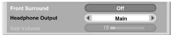
text_image
Front Surround Headphone Output Sub Volume Off Main 15Item Description
Main Audio coming from the main screen is output from the PHONES output terminal.
Sub When in the 2-screen or picture-in-picture mode, audio coming from the sub screen is output from the PHONES output terminal.
5 Select "Sub Volume" (/)↑↓
6 Select the desired volume level (/)←→

text_image
Front Surround Off Headphone Output Sub Sub Volume 157 Press HOME MENU to exit the menu.

NOTE
- To adjust the volume for headphones after selecting "Sub", always use the menu item (shown in the procedure) no matter whether the screen is in the single, 2-screen, or picture-in-picture mode. When the screen is in the single mode with "Sub" selected, audio coming from the screen is output from speakers even with headphones connected.
- To adjust the volume of audio coming from the active (or main screen) with headphones, select "Main" in step 4 then press + / - on the remote control unit.
Power Control
Power Control provides convenient functions for power saving.
Energy Save
You may use one of the three Energy Save modes to save power consumption.
1 Press HOME MENU.
2 Select "Power Control" ( / then ENTER).
3 Select "Energy Save" ( / then ENTER).
4 Select "Save1", "Save 2" or "Picture Off" (/ then ENTER).
Item Description
Standard Does not decrease the picture brightness.
| Save1 Slightly lowers power consumption while slightly suppressing the brightness drop level. |
| Save2 Decreases the picture brightness and lowers power consumption. |
| Picture Off | Deactivates the screen to save power. To restore the screen display, press any button other than + / - and 吸 .This setting is not memorised by the system. |
5 Press HOME MENU to exit the menu.
No Signal off (AV mode only)
The system will be automatically placed into the standby mode if no signal is received for 15 minutes.
1 Press HOME MENU.
2 Select "Power Control" (▲/▼ then ENTER).
3 Select "No Signal off" ( / then ENTER).
4 Select "Enable" (▲/↓ then ENTER).
Item Description
| Disable(factory default) | Does not place the system into the standby mode. |
Enable Places the system into the standby mode if no signal is received for 15 minutes.
5 Press HOME MENU to exit the menu.

NOTE
- Five minutes before the system is placed into the standby mode, a message appears every minute.
- The system may not be placed into the standby mode when noise signals are present at the Media Receiver after a TV program finishes.
No Operation off (AV mode only)
The system will be automatically placed into the standby mode when no operation is performed for three hours.
1 Press HOME MENU.
2 Select "Power Control" (▲/↓ then ENTER).
3 Select "No Operation off" (▲/↓ then ENTER).
4 Select "Enable" (▲/↓ then ENTER).
Item Description
| Disable(factory default) | Does not place the system into the standby mode. |
Enable Places the system into the standby mode if no operation is performed for three hours.
5 Press HOME MENU to exit the menu.

NOTE
- Five minutes before the system is placed into the standby mode, a message appears every minute.
Power Management (PC mode only)
The system will be automatically placed into the standby mode when no signal is received from the personal computer.
1 Press HOME MENU.
2 Select "Power Control" (▲/▼ then ENTER).
3 Select "Power Management (↑/↓ then ENTER).
4 Select "Mode 1" or "Mode 2" (↑/↓ then ENTER).
Item Description
| Off (factory default) | No power management |
Mode1 • Places the system into the standby mode
when no signal is received from the personal computer for eight minutes.
- Even when you start using the computer and a signal is received again, the system stays off.
- The system is switched on again by pressing STANDBY/ON on the Media Receiver or TV ⏻ on the remote control unit.
Mode2 • Places the system into the standby mode
when no signal is received from the personal computer for eight seconds.
- When you start using the computer and a signal is input again, the system is switched on.
- The system is switched on again by pressing STANDBY/ON on the Media Receiver or TV ⏻ on the remote control unit.
5 Press HOME MENU to exit the menu.
Switching the vertical drive frequency
You can switch the vertical drive frequency for screen display between 75 Hz and 100 Hz. Choose the drive frequency that better suits your broadcasting signals.
1 Press HOME MENU.
2 Select "Option" (↑/↓ then ENTER).
3 Select "Drive Mode" (↑/↓ then ENTER).
4 Select 75 Hz or 100 Hz ( / then ENTER).

text_image
Drive Mode ● 75Hz 100Hz5 Press HOME MENU to exit the menu.

NOTE
- Selection can be performed for each input source separately.
- Selections are effective only for the following input signals: PAL/SECAM (576i, 576p, 1080i@50Hz, 720p@50Hz)
- Selections are ineffective for 1080p@24Hz.
- If you select "Auto" for "Side Mask" (page 40), the selection for "Drive Mode" becomes ineffective.
Adjusting image positions (AV mode only)
Adjust the horizontal and vertical positions of images on the Plasma Display.
1 Press HOME MENU.
2 Select "Option" (↑/↓ then ENTER).
3 Select "Position" (↑/↓ then ENTER).
4 Select "H/V Position Adjust" (↑/↓ then ENTER).

text_image
Position H/V Position Adjust Reset5 Adjust the vertical position (/) on the horizontal position (←)
6 Press HOME MENU to exit the menu.

NOTE
- To restore the factory defaults for all items, press to select "Reset" in step 4, and then press ENTER. A confirmation screen appears. Press to select "Yes", and then press ENTER.
- Adjustments are stored separately according to input source.
Adjusting image positions and clock automatically (PC mode only)
Use Auto Setup to automatically adjust the positions and clock of images coming from a personal computer.
1 Press HOME MENU.
2 Select "Option" ( / then ENTER).
3 Select "Auto Setup" (↑/↓ then ENTER).

text_image
Option Auto Setup Manual Setup- Auto Setup starts.
4 Press HOME MENU to exit the menu.

NOTE
- When Auto Setup is finished, "Auto Setup completed." appears.
- Even when "Auto Setup completed." appears, Auto Setup may have failed, depending on conditions.
- Auto Setup may fail with a PC image composed of similar patterns or monochrome. If not successful, change the PC image and try again.
- Be sure to connect the computer to the Media Receiver and switch it on before starting Auto Setup.
Adjusting image positions and clock manually (PC mode only)
Usually you can easily adjust the positions and clock of images using Auto Setup. Use Manual Setup to optimize the positions and clock of images when necessary.
1 Press HOME MENU.
2 Select "Option" (↑/↓ then ENTER).
3 Select "Manual Setup" (↑/↓ then ENTER).
4 Select the item to be adjusted ( / then ENTER).
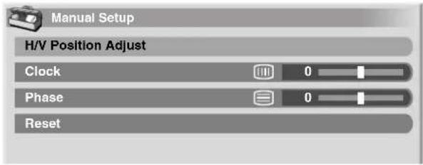
text_image
Manual Setup H/V Position Adjust Clock 0 Phase 0 Reset5 Perform adjustment (/ ◆ and /). ↑ ↓
- With "Clock" or "Phase" selected, you can change the parameter using .
6 Press HOME MENU to exit the menu.

NOTE
- To restore the factory defaults for all the items, press ⚠ to select "Reset" in step 4, and then press ENTER. A confirmation screen appears. Press ⚠ to select "Yes", and then press ENTER.
Changing the color system
If an image does not appear clearly, select another color system (e.g., PAL, NTSC).
1 Press HOME MENU.
2 Select "Option" (↑/↓ then ENTER).
3 Select "Color System" (↑/↓ then ENTER).
4 Select a video signal system ( / then ENTER).

text_image
Color System ● Auto PAL SECAM NTSC 4.43NTSC- You can select "Auto", "PAL", "SECAM", "NTSC", "4.43NTSC", "PAL-M", or "PAL-N".
- With "Auto" selected, input signals are automatically identified.
5 Press HOME MENU to exit the menu.

NOTE
• The factory default is "Auto".
- You need to perform color system setting for each of INPUT 1 to 4.
- For the color system setting, see steps 11 and 12 under "Using Manual Adjust" (page 28).
Selecting a screen size manually
Press 🏠 to switch among the screen size options selectable for the type of video signals currently received.
• Each time you press 📋, the selection is switched.
- The selectable screen sizes differ depending on the types of input signals.
AV mode
Item Description
| 4:3 | For 4:3 "standard" pictures. A side mask appears on each side. |
| FULL 14:9 | For 14:9 squeeze pictures. A thin side mask appears on each side. |
| CINEMA 14:9 | For 14:9 letterbox pictures. A thin side mask appears on each side, and you may also see bars on the top and bottom with some programs. |
| WIDE | In this mode the picture is progressively stretched toward each side of the screen. |
| FULL | For 16:9 squeeze pictures. |
| ZOOM | For 16:9 letterbox pictures. Bars may appear on the top and bottom with some programs. |
| CINEMA | For 14:9 letterbox pictures. Bars may appear on the top and bottom on some programs. |
PC mode except for XGA signals
Item Description
4:3 Fills the screen without altering the input signal aspect ratio.
FULL Full 16:9 screen display
Dot by Dot Matches input signal with same number of screen pixels.
PC mode for XGA signals
(Ex. 1024 × 768 input at PDP-506HDG)
Item Description
4:3 Matches input signal with the same number of screen pixels. Optimized for 1024 × 768 display
FULL1 Full 16:9 screen display Optimized for 1024 × 768 display
FULL2 For wide signal display Use when displaying 1280 × 768 signal resolution.

NOTE
- The specifications given for the PC mode is for the PDP-506HDG. For the PDP-436HDG, the number of panel pixels is different, and thus signal processing and actual viewing conditions will vary slightly.

flowchart
graph TD
    A["4:3"] --> B["CINEMA"]
    A --> C["FULL 14:9"]
    B --> D["ZOOM"]
    C --> E["CINEMA14:9"]
    D --> F["FULL"]
    E --> G["WIDE"]
    F <--> G

NOTE
- While watching High Definition TV broadcasting, pressing switches among FULL, WIDE, 4:3, and ZOOM.
Selecting a screen size automatically
The Plasma Display automatically selects an appropriate screen size when the received video signals contain WSS (wide screen signaling) information or when video signals are received from a connected HDMI equipment (see page 47). To activate this function, use the following procedure.
1 Press HOME MENU.
2 Select "Option" ( / then ENTER).
3 Select "Auto Size" (▲/↓ then ENTER).
4 Select "On" (↑/↓ then ENTER).

text_image
Auto Size ● Off OnItem Description
Off
Deactivates the Auto Size function.
(factory default)
On Activates the Auto Size function.
5 Press HOME MENU to exit the menu.

NOTE
- Manually select an appropriate screen size if an image does not automatically switch to a correct screen format.
- When the video signal contains no aspect ratio information, the function will not work even with "On" selected.
Selecting a screen size for received 4:3 aspect ratio signals
Specify whether the Plasma Display should choose the 4:3 mode or WIDE mode when 4:3 aspect ratio signals are received with the Auto Size function activated.
1 Press HOME MENU.
2 Select "Option" (↑/↓ then ENTER).
3 Select "4:3 Mode" (↑/↓ then ENTER).
4 Select "WIDE" or "4:3" (↑/↓ then ENTER).

text_image
4:3 Mode ● WIDE 4:3Item Description
WIDE
Wide image without side masks.
(factory default)
4:3 Keeps the 4:3 aspect ratio and presents side masks.
4:3WIDE

natural_image
Exterior view of a two-story house surrounded by trees (no signage or text visible)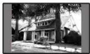
natural_image
Exterior view of a two-story house surrounded by trees and open ground (no signage or text visible)5 Press HOME MENU to exit the menu.
Changing the brightness at both sides of the screen (Side Mask)
With the 4:3, FULL 14:9, or CINEMA 14:9 screen size selected for the AV mode, you can change the brightness of the grey side masks that appear at both sides of the screen.
1 Press HOME MENU.
2 Select "Option" (↑/↓ then ENTER).
3 Select "Side Mask" ( / then ENTER).
4 Select the desired parameter ( / then ENTER).
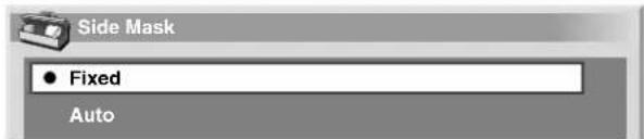
text_image
Side Mask ● Fixed AutoItem Description
Fixed
Always sets the same brightness for the grey side masks.
(factory default)
Auto Adjusts the brightness of the grey side masks according to the brightness of images.
5 Press HOME MENU to exit the menu.

NOTE
- If you select "Auto", the selection for "Drive Mode" (page 38) becomes ineffective.
Sleep Timer
When the selected time elapses, the Sleep Timer automatically places the system into the standby mode.
1 Press HOME MENU.
2 Select "Sleep Timer" (↑/↓ then ENTER).
3 Select the desired time ( / then ENTER).
- You can select from among "Off" (cancel), "30 min", "60 min", "90 min", and "120 min".
4 Press HOME MENU to exit the menu.

NOTE
- Five minutes before the selected time elapses, the remaining time appears every minute.
- To check the remaining time, perform steps 1 and 2. After checking the time, press HOME MENU to restore the previous display.
Using a password (AV mode only)
The Plasma Display System provides the Child Lock function for preventing children from watching inappropriate programs. You need to enter a password when watching programs with "Block" specified. Before the system is shipped, "1234" is preset as the factory-default password. You can however, change the password as you want.
When using the Home menu you select "Auto Installation", "Program Setup", or "Password", a screen prompting password entry appears to prevent others from changing the program settings at their choices.
Entering a password
In a case where you select a channel blocked with Child Lock or password entry is requested when attempting to open the menu, enter a password correctly.
1 Enter a correct 4-digit password using buttons 0 - 9.
Please Input Your Password.


NOTE
- If you fail password entry three times, "Invalid password." appears, and the menu is closed. In order to display the password entry screen again to unlock the password, select the blocked channel or open the menu again.
- If the password entry screen disappears before entry, you may recall it by pressing ENTER.
Changing the password
Use the following procedure to change the password.
1 Press HOME MENU
2 Select "Setup" (▲/▼ then ENTER).
3 Select "Password" (▲/↓ then ENTER).
- The password entry screen appears. Enter the current 4-digit password using buttons 0 - 9.
4 Select "Change Password" (▲/↓ then ENTER).

text_image
Change Password Please Input New Password. Reconfirm New Password.5 Enter a 4-digit password to be newly set, using buttons 0-9.
6 Enter the same password that you have entered in step 5.
- If an unmatching password is entered, the operation goes back to step 5 for reentry from the beginning.
- If you fail password change three times by entering unmatching passwords, the menu is closed.
7 Press HOME MENU to exit the menu.

NOTE
• Take a note of the newly set password and keep it handy.
Resetting the password function
1 Press HOME MENU.
2 Select "Setup" (▲/↓ then ENTER).
3 Select "Password" (▲/↓ then ENTER).
- The password entry screen appears. Enter your 4-digit password using buttons 0 - 9.
4 Select "Reset" (↑/↓ then ENTER).
5 Select "Yes" (↑/↓ then ENTER).
6 Press HOME MENU to exit the menu.
NOTE
- The above procedure will reset the password to the factory default (1234).
We suggest you write down your password so you don't forget it.

text_image
PDP-506HDG/PDP-436HDG Your password No.: □ □ □ □If you forget the password
When the message "Please Input Your Password," is displayed in the above procedure, press the ENTER button on the remote control unit and hold it down for 3 seconds or longer.
The password reverts to "1234".
What is Teletext?
Teletext broadcasts pages of information and entertainment to specially equipped television sets. Your Plasma Display System receives Teletext signals broadcast by TV networks, and decodes them into graphical format for viewing. News, weather and sports information, stock exchange prices and program previews are among many services available.
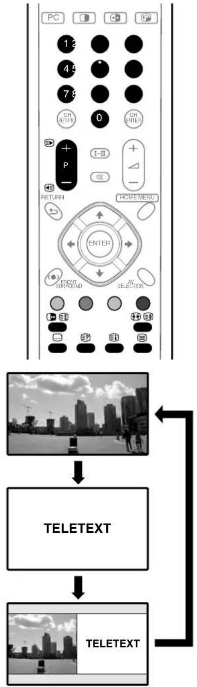
flowchart
graph TD
    A["PC"] --> B["1 2"]
    B --> C["4 5"]
    C --> D["7 8"]
    D --> E["CH RETURN"]
    E --> F["0"]
    F --> G["CH ENTER"]
    G --> H["+ P"]
    H --> I["I-II"]
    I --> J["+ △"]
    J --> K["-"]
    K --> L["RETURN"]
    L --> M["HOME MENU"]
    M --> N["ENTER"]
    N --> O["FRONT SURROUND"]
    O --> P["AV SELECTION"]
    P --> Q["1 2"]
    Q --> R["3?"]
    R --> S["3?"]
    S --> T["3?"]
    T --> U["3?"]
    U --> V["3?"]
    V --> W["3?"]
    W --> X["3?"]
    X --> Y["3?"]
    Y --> Z["3?"]
    Z --> AA["3?"]
    AA --> AB["3?"]
    AB --> AC["3?"]
    AC --> AD["3?"]
    AD --> AE["3?"]
    AE --> AF["3?"]
    AF --> AG["3?"]
    AG --> AH["3?"]
    AH --> AI["3?"]
    AI --> AJ["3?"]
    AJ --> AK["3?"]
    AK --> AL["3?"]
    AL --> AM["3?"]
    AM --> AN["3?"]
    AN --> AO["3?"]
    AO --> AP["3?"]
    AP --> AQ["3?"]
    AQ --> AR["3?"]
    AR --> AS["3?"]
    AS --> AT["3?"]
    AT --> AU["3?"]
    AU --> AV["3?"]
    AV --> AW["3?"]
    AW --> AX["3?"]
    AX --> AY["3?"]
Operating the Teletext basics
Turning on and off Teletext
1 Select a TV channel or external input source providing a Teletext program.
2 Press ☐ to display the Teletext (full screen).
3 Press ☑ again to display the Teletext on the right screen and normal image on the left screen.
• Each time you press ☐, the screen switches as shown to the left.
- If you select a program with no Teletext signal, "Cannot display Teletext." appears.
Selecting and operating Teletext pages
Use the following remote control buttons to select and operate Teletext pages.
Color (RED/GREEN/YELLOW/BLUE):
You can select a group or block of pages displayed in the colored brackets at the bottom of the screen by pressing the corresponding color (RED/GREEN/YELLOW/BLUE) on the remote control unit.
0 - 9:
Directly select any page from 100 to 899 by using 0 - 9.
三▶/←:
Selects the next or previous page.
三
Each time you press Ⓗ, the teletext image switches as shown below.
三?:
To display hidden information such as an answer to a quiz, press ≡?
- Press ☑ again to hide the information.
三:
To stop updating Teletext pages, press
- Press again to release the hold mode.
i:
Displays an Index page for the CEEFAX/FLOF format. Displays a TOP Over View page for the TOP format.

NOTE
- Before displaying the Teletext, return the screen to the single-screen mode.
Displaying subpages
You can display several subpages as they are transmitted.
Subpage screen

text_image
203 203TEXT 01:44:37 P- P+ Life Promis 01 02 03 041 Press ☐ to display Teletext.
- If you open a page containing subpages, the subpages are automatically displayed in sequence.
2 To quit automatic subpage change, press / .
- You can then manually change subpages by pressing / .
NOTE
- Pressing ▶/◀ causes the page to be changed and the subpage screen to disappear.
- Pressing stops automatic subpage change and performs its respective button function.
Enjoying through External Equipment
You can connect many types of external equipment to your Plasma Display System, like a VCR, DVD player, personal computer, game console, and camcorder. To view images coming from external equipment, select the input source using the INPUT buttons on the remote control or the INPUT button on the Media Receiver.

CAUTION
• To protect all equipment, always unplug the Media Receiver from the power outlet before connecting to a VCR, DVD player, personal computer, game console, camcorder, or other external equipment.

NOTE
- Refer to the relevant operation manual (DVD player, personal computer, etc.) carefully before making connections.
Watching a DVD image
Connecting a DVD player
Use the INPUT 2 terminal when connecting to a DVD player and other audiovisual equipment.
Media Receiver (rear view)

text_image
Component cable (commercially available) S-Video cable (commercially available) AV cable (commercially available) DVD playerDisplaying a DVD image
To watch a DVD image, press INPUT 2 on the remote control unit or press INPUT on the Media Receiver to select INPUT2.

NOTE
- Refer to your DVD player operation manual for the signal type.
- The INPUT 2 terminal is checked for cable connections in the order where: 1) Component Video, 2) S-Video, 3) Video.
- Connect the external equipment to only terminals that are to actually used.
Watching a VCR image
Connecting a VCR
Use the INPUT 3 terminal when connecting a VCR and other audiovisual equipment.
Media Receiver (rear view)
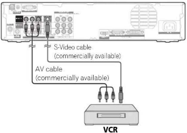
text_image
S-Video cable (commercially available) AV cable (commercially available) VCRDisplaying a VCR image
To watch a VCR image, press INPUT 3 on the remote control unit or press INPUT on the Media Receiver to select INPUT3.

NOTE
• Refer to your VCR operation manual for the signal type.
- The INPUT3 terminal is checked for cable connections in the order where; 1) S-Video, 2) Video.
- Connect the external equipment to only terminals that are to actually used.
Watching broadcasts via a digital tuner
Connecting a digital tuner
You can use the INPUT 1 terminal when connecting a digital tuner and other audiovisual equipment.
Media Receiver (rear view)

text_image
S-Video cable (commercially available) Component cable (commercially available) AV cable (commercially available) Digital tunerDisplaying broadcasts via a digital tuner
To watch a digital tuner image, press INPUT 1 on the remote control unit or press INPUT on the Media Receiver to select INPUT1.

NOTE
- Refer to your digital tuner operation manual for the signal type.
- The INPUT 1 terminal is checked for cable connections in the order where: 1) Component video, 2) S-Video, 3) Video.
- Connect the external equipment to only terminals that are to actually used.
Enjoying a game console and watching camcorder images
Connecting a game console or camcorder
Use the INPUT 4 terminal to connect a game console, camcorder, and other audiovisual equipment.
Media Receiver (front view)

text_image
S-Video cable (commercially available) AV cable (commercially available) Game console/ CamcorderDisplaying an image from the game console or camcorder
To watch an image coming from the game console or camcorder, press INPUT 4 on the remote control unit or press INPUT on the Media Receiver to select INPUT4.

NOTE
- The INPUT 4 terminals are checked for cable connections in the order where: 1) S-Video, 2) Video.
- Connect external equipment to only terminals that are to be actually used.
Watching an image from a personal computer
Connecting a personal computer
Use the PC terminals to connect a personal computer.

NOTE
• The PC input terminals are DDC1/2B-compatible.
Media Receiver (front view)
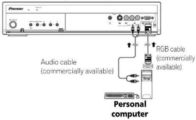
text_image
Pioneer Audio cable (commercially available) RGB cable (commercially available) Personal computerDisplaying an image from a personal computer
To watch an image coming from the personal computer, press PC on the remote control unit or press INPUT on the Media Receiver to select "PC".
When connecting to a personal computer, the correct input signal type is automatically detected. If the personal computer image does not come in clearly, you may need to use Auto Setup menu. See page 38.

NOTE
- The PC terminals cannot be used for audiovisual equipment.
Computer compatibility chart
| Resolution Frequency Remarks | |
| 720 × 400 70 Hz | |
| 640 × 480 60 Hz | |
| 72 Hz | |
| 75 Hz | |
| 800 × 600 56 Hz | |
| 60 Hz | |
| 72 Hz | |
| 75 Hz | |
| 1024 × 768 60 Hz | |
| 70 Hz | |
| 75 Hz | |
| 1280 × 768 56 Hz | |
| 60 Hz | |
| 70 Hz | |
Enjoying through audio equipment in connection
Connecting audio equipment
You can enjoy more powerful sound by connecting such audio equipment as an AV receiver.
Media Receiver (rear view)
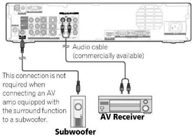
text_image
Audio cable (commercially available) This connection is not required when connecting an AV amp equipped with the surround function to a subwoofer. Subwoofer AV Receiver
NOTE
- For details, refer to the operation manual for the audio equipment to be connected.
• Audio corresponding to video signals for the current image display is always output to the MONITOR OUT terminals. - Audio from a connected subwoofer is muted when you have selected "Sub" for "Headphone Output" (page 36) and connected headphones.
Avoiding unwanted feedback
You can prevent unwanted feedback from adversely affecting the quality of images. Specify the output terminal whose output is to be inhibited.
1 Press HOME MENU.
2 Select "Option" (↑/↓ then ENTER).
3 Select "Monitor Out" (▲/↓ then ENTER).
4 Select the desired parameter ( / then ENTER).
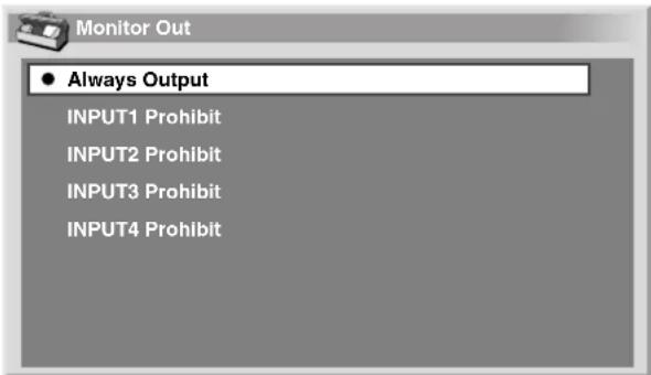
text_image
Monitor Out ● Always Output INPUT1 Prohibit INPUT2 Prohibit INPUT3 Prohibit INPUT4 ProhibitItem Description
| Always Output Outputs composite video and audio signals no matter which input source is selected. | |
| INPUT1 Prohibit | Does not output composite video and audio signals when INPUT 1 is selected. |
| INPUT2 Prohibit | Does not output composite video and audio signals when INPUT 2 is selected. |
| INPUT3 Prohibit | Does not output composite video and audio signals when INPUT 3 is selected. |
| INPUT4 Prohibit | Does not output composite video and audio signals when INPUT 4 is selected. |
5 Press HOME MENU to exit the menu.
Using HDMI Input
The INPUT 3 terminals include HDMI terminals to which digital video and audio signals can be input. To use the HDMI terminal, activate the terminal and specify the types of video and audio signals to be received from the connected equipment. For the types of these signals, see the operation manual that came with the connected equipment.
Input signal correlation table
| 1920*1080i@50Hz |
| 720*576p@50Hz |
| 1280*720p@50Hz |
| 720(1440)*576i@50Hz |
| 1920*1080i@59.94/60Hz |
| 720*480p@59.94/60Hz |
| 1280*720p@59.94/60Hz |
| 720(1440)*480i@59.94/60Hz |
| 1920*1080p@24Hz |
For audio, the system supports the following:
• Linear PCM (STEREO 2ch)
• Sampling frequency: 32 kHz, 44.1 kHz, 48 kHz

NOTE
• PC signals are out of correspondence.
Connecting HDMI equipment
Media Receiver (rear view)

text_image
HDMI cable (commercially available) Audio cable (commercially available) Make this connection when inputting analog audio signals. HDMI equipmentTo activate the HDMI terminal:
1 Press HOME MENU.
2 Select "Option" ( / then ENTER).
3 Select "HDMI Input" ( / then ENTER).
4 Select "Setting" ( / then ENTER).
5 Select "Enable" (↑/↓ then ENTER).
Item Description
| Disable(factory default) | Deactivates the HDMI terminal. |
Enable Activates the HDMI terminal.
6 Press HOME MENU to exit the menu.
To specify the type of digital video signals:
1 Repeat steps 1 to 3 provided for "To activate the HDMI terminal".
2 Select "Video" (↑/↓ then ENTER).
3 Select the type of digital video signals ( / then ENTER).
- If you select "Auto", an attempt will be made to identify the type of digital video signals when digital video signals are received.
Item Description
| Auto (factory default) | Automatically identifies input digital video signals. |
| Color-1 Sets the format of digital video signals to the Component 4:2:2. | |
| Color-2 Sets the format of digital video signals to the Component 4:4:4. | |
| Color-3 Sets the format of digital video signals to the RGB. | |
4 Press HOME MENU to exit the menu.

NOTE
- If you select a parameter other than "Auto", make such a setting that results in natural color.
- If no image appears or images appear in inappropriate colors, specify another digital video signal type.
- For the digital signal types to be specified, check the operation manual that came with the connected equipment.
To specify the type of audio signals:
1 Repeat steps 1 to 3 provided for "To activate the HDMI terminal".
2 Select "Audio" ( / then ENTER).
3 Select the type of audio signals ( / then ENTER).
- If you select "Auto", an attempt will be made to identify the type of audio signals when audio signals are received.
Item Description
| Auto (factory default) | Automatically identifies input audio signals. |
| Digital Accepts digital audio signals. | |
| Analog Accepts analog audio signals. | |
4 Press HOME MENU to exit the menu.

NOTE
- If no sound is output, specify another audio signal type.
- For the signal types to be specified, check the operation manual that came with the connected equipment.
- Depending on the equipment to be connected, you also need to connect analog audio cables.
Connecting control cords
Connect control cords between the Media Receiver and other PIONEER equipment having the SR logo. You can then operate the connected equipment by sending commands from its remote control unit to the remote control sensor on the Plasma Display.
After the CONTROL IN terminals have been connected, the remote control sensors on the connected equipment do not accept commands from the remote control units. Face the remote control units to the remote control sensor on the Plasma Display when operating the connected equipment.

NOTE
- Make sure that the power is turned off when making connections.
- Complete all component connections before making control cord connections.
About SR+
The CONTROL OUT terminal on the rear of the Media Receiver supports SR+ that allows linked operations with a PIONEER AV receiver. SR+ presents functions such as the input switch linkage operation function and the DSP surround mode display function. For more information, see the user's manual for the PIONEER AV receiver supporting SR+.

NOTE
- While in connection through SR+, the volume on this system is temporarily minimized.
Media Receiver (rear view)

flowchart
graph TD
    A["Device 1"] --> B["Port 1"]
    B --> C["Port 2"]
    C --> D["Port 3"]
    D --> E["Port 4"]
    E --> F["Port 5"]
    F --> G["Port 6"]
    G --> H["Port 7"]
    H --> I["Port 8"]
    I --> J["Port 9"]
    J --> K["Port 10"]
    K --> L["Port 11"]
    L --> M["Port 12"]
    M --> N["Port 13"]
    N --> O["Port 14"]
    O --> P["Port 15"]
    P --> Q["Port 16"]
    Q --> R["Port 17"]
    R --> S["Port 18"]
    S --> T["Port 19"]
    T --> U["Port 20"]
The control cables (commercially available) are monaural cables with mini plugs (no resistance).
Troubleshooting
| Problem Possible Solution | |
| No power. | Make sure that the Plasma Display and the Media Receiver are connected correctly. (See page 17.)Is the power cord disconnected? (See page 20.)Has the main power been turned on? (See page 21.)Check if you pressed buttons 0-9 or ⏻ on the remote control unit. (See page 21.)If the indicator on the system lights up red, press 0-9 or ⏻ on the remote control. |
| Blue and red rectangles appear on the screen alternately. | Check if the system cable has been disconnected or almost disconnected? (See page 17.) |
| The system cannot be operated. | External influences such as lightning, static electricity, etc., may cause improper operation.In this case, operate the system after first turning the power of the Plasma Display and the Media Receiver, or unplugging the power cord and re-plugging it in after 1 or 2 minutes. |
| Remote control unit does not operate. | Are batteries inserted with polarity (+,-) aligned? (See page 19.)Are batteries worn out? Replace with new batteries. (See page 19.)Operate the remote control unit while pointing it toward the remote control sensor on the Plasma Display. (See page 19.)Are you using it under strong or fluorescent lighting?Is a fluorescent light illuminated to remote control sensor? |
| No image and audio is presented. | Check if the input source for video or PC has been unintentionally selected although you want to watch a TV channel. (See page 22.)Check if you have selected a channel blocked with Child Lock. (See page 29.)Enter a password to temporarily cancel Child Lock. (See page 41.)Check the cable connection with the antenna. (See page 20.)Check the cable connection with the other equipment. (See pages 44 to 49.) |
| No picture. Is connection to other components correct? (See pages 44 to 49.)Is a non-compatible PC signal being input? (See page 46.) | |
| Images are presented but no audio is output. | Check if you have selected the minimum volume. (See page 22.)Check if you have muted sound. (See page 22.)When using a video or PC as the input source, check that the audio terminal is also in connection. (See pages 44 to 47.)Check the sound system selected for a TV channel where problems have occurred. (See page 28.)Reselect the correct sound system. |
| Sound is reversed between the right and left.Sound is output from only a single speaker. | Check if the speaker cable connections have been reversed between the right and left or if the speaker cable from either speaker has been disconnected. (See pages 12 and 18.)Has the balance been correctly adjusted? (See page 35.) |
| Picture is cut off. Is the image position correct? (See page 38.)Has the correct screen size been selected? (See page 39.) | |
| Strange color, light color, dark or color misalignment. | Adjust the picture lone. (See pages 32 to 34.)Is the room too bright? The picture may look dark in a room that is too bright.Check the color system setting. (See pages 28 and 39.) |
| Power is suddenly turned off. | The system's internal temperature has increased. Remove any objects blocking vent or clean. (See page 15.)Check the power control setting. (See page 37.)Check the sleep timer setting. (See page 40.) |
| Panel sounds /noises | Panel generated sounds,examples: Fan motor noise, Electrical Circuit Humming /Glass Panel buzzing are normal operation of a phosphor-based matrix display. |
If the following error codes appear on the screen, check the corresponding items in the table.
Code Message Check
| SD04 | Powering off. Internal temperature too high.Check temperature around PDP. | Check if the ambient temperature of the Plasma Display is high. |
| SD05 | Powering off. Internal protection circuits activated, Is there a short in speaker cable? | Check the speaker cable connections between the Plasma Display and the speakers. |
| SD11 | Powering off. Internal temperature too high.Check temperature around media receiver. | Check if the ambient temperature of the Plasma Display and the Media Receiver is high. |
Signal names for 15-pin mini D-sub connector

text_image
5 4 3 2 1 10 9 8 7 6 15 14 13 12 11(Front view)
Pin No. Signal name
| 1 | R |
| 2 | G |
| 3 | B |
| 4 Not connected | |
| 5 Not connected | |
| 6 GND (ground) | |
| 7 GND (ground) | |
| 8 GND (ground) | |
Pin No. Signal name
| 9 | 15V |
| 10 GND (ground) | |
| 11 Not connected | |
| 12 SDA | |
| 13 HD | |
| 14 VD | |
| 15 SCL | |
Standard Channel Allocation Selections for the Countries and Regions
Region Standard Channel Allocation Selection
| Taiwan Cable (US Type) | |
| Hong Kong Normal | |
| Philippines Cable (US Type) | |
| Thailand Normal | |
| Malaysia Normal | |
| Singapore Normal | |
| Indonesia Normal | |
| Saudi Arabia | Normal |
| Israel | Normal |
| Lebanon Normal | |
| United Arab Emirates | Normal |
| Mexico | Cable (US Type) |
| Chile | Cable (US Type) |
| Brazil | Cable (US Type) |
| Australia | Normal |
| New Zealand | Normal |
| Egypt | Normal |
| South Africa | Normal |
Specifications
| Item | 50" Plasma Display, Model: PDP-506PG | 43" Plasma Display, Model: PDP-436PG |
| Number of Pixels 1280 × 768 pixels | 1024 × 768 pixels | |
| Audio Amplifier | 13 W + 13 W (1 kHz, 10 %, 8 Ω) | 13 W + 13 W (1 kHz, 10 %, 8 Ω) |
| Surround System SRS/FOCUS/TruBass | SRS/FOCUS/TruBass | |
| Power Requirement 110 – 240 V ~ | 50/60 Hz, 355 W (0.4 W Standby) 110 – 240 V ~, 50/60 Hz, | 295 W (0.4 W Standby) |
| Dimensions 1224 (W) × 717 (H) × | 92 (D) mm 1076 (W) × 632 (H) × 92 (D) mm | |
| Weight | 31.8 kg (70.1 lbs.) | 25.8 kg (56.9 lbs.) |
| Item | Media Receiver, Model: PDP-R06G | ||
| Color System | PAL/SECAM/NTSC/4.43NTSC/PAL-M/PAL-N | ||
| TV Function | Receiving System | PAL: B/G, D/K, I SECAM: B/G, D/K NTSC: M, N | |
| Tuner | VHF/UHF | 44.25–863.25 MHz | |
| CATV | Hyper-band, S1–S41ch | ||
| Auto Channel Preset | 99 ch (Normal), 68 ch (Air, US type), 125 ch (Cable, US type), Auto Preset | ||
| Audio multiplex | NICAM/A2/BTSC System | ||
| Terminals | Rear | INPUT 1 | COMPONENT VIDEO in, S-VIDEO in, AV in |
| INPUT 2 | COMPONENT VIDEO in, S-VIDEO in, AV in | ||
| INPUT 3 | S-VIDEO in, AV in, HDMI in* | ||
| Antenna | 75 Ω Din Type for VHF/UHF in | ||
| Front | INPUT 4 | S-VIDEO, AV in (Audio input is shared with PC INPUT.) | |
| PC | Analogue RGB in | ||
| MONITOR OUT Terminal | (Rear) AV out | ||
| PHONES OUTPUT Terminal (Front) | 16 – 32 Ω recommended | ||
| SUB WOOFER OUTPUT Terminal (Rear) | Variable | ||
| Power Requirement | 110 – 240 V --- , 50/60 Hz, 16 W (0.4 W Standby) | ||
| Dimensions | 420 (W) × 90 (H) × 299 (D) mm | ||
| Weight | 3.4 kg | ||
* This conforms to HDMI1.1 and HDCP1.1.
HDMI (High Definition Multimedia Interface) is a digital interface that handles both video and audio using a single cable. HDCP (High-bandwidth Digital Content Protection) is a technology used to protect copyrighted digital contents that use the Digital Visual Interface (DVI).
- Design and specifications are subject to change without notice.
Trademarks
- FOCUS, WOW, SRS and (●)® symbol are trademarks of SRS Labs, Inc.
FOCUS and SRS technologies are incorporated under license from SRS Labs, Inc.
- This product includes FontAvenue® fonts licensed by NEC Corporation. FontAvenue is a registered trademark of NEC Corporation.
- Microsoft is a registered trademark of Microsoft Corporation.
- HDMI, the HDMI logo and High-Definition Multimedia Interface are trademarks or registered trademarks of HDMI Licensing LLC.
• The names of the companies or institutions are trademarks or registered trademarks of the respective companies or institutions.
Published by Pioneer Corporation.
Copyright © 2005 Pioneer Corporation.
All rights reserved.
IMPORTANTE

Media Receiver ....11
Media Receiver ....12
Mando a distancia ....14
05 Preparación
natural_image
Simple line drawing of a folded paper or fabric (no text or symbols)Paño de limpieza

Tarjeta de garantía

Núcleo de ferrita

natural_image
Simple line drawing of a tool or bracket with a handle and base (no text or symbols)Abrazadera de cables
Media Receiver

natural_image
Two cylindrical batteries with metallic leads, shown in black and white (no text or symbols)
natural_image
Line drawing of a remote control with scroll and keypad (no text or symbols)
natural_image
Coiled electronic device with two connectors and a central connector (no text or symbols visible)natural_image
Simple 3D illustration of a blank rectangular block (no text or symbols)
NOTA
text_image
Diagram of a TV rear panel with labeled ports and connectors, showing internal layout and component placement.text_image
1 2 3 4 5 6 7 8 9 10 11 12 13 14 15 PIONEER PLASMA DISPLAY INPUT 1 2 3 4 PC 1 2 3 4 5 6 7 8 9 0 INTES INTES INTES INTES INTES INTES INTES INTES INTES INTES INTES INTES INTES INTES INTES INTES INTES INTES INTES INTES INTES INTES INTES INTES INTES INTES INTES INTES INTES INTES INTES INTES INTES INTES1 ⏻
natural_image
Simple line drawing of a smartphone with two crossed X-shaped bars (no text or symbols)text_image
(NEGRO) (BLANCO)text_image
(NEGRO) (BLANCO)natural_image
Technical line drawing of a mechanical assembly with mounting holes and a close-up inset showing a cylindrical component (no text or symbols)text_image
Diagram illustrating two mechanical or electrical setups with labeled components and directional arrows indicating movement or force.Media Receiver (vista trasera)

Media Receiver (Vista frontal)

text_image
Pioneer OFF/24/01 OUTRANGE IPT + FULZIN + + COLDING + CHANNEL +/-
text_image
1 2 3 4 5 6 7 8 9 0 + - RETURN I-1 + - +/-Media Receiver (Vista frontal)

text_image
Pioneer VOLUME +/-
Ajuste del volumen

text_image
28Silenciamiento

text_image
OK 28Cambio de canales
natural_image
Black-and-white photo showing a lakeside building with trees and a sailboat on water, alongside a distant mountain range (no visible text or symbols)Pantalla secundaria Pantalla principal
Imagen-en-imagen
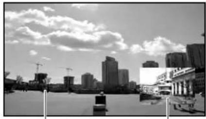
natural_image
Black-and-white cityscape with modern high-rise buildings and construction cranes under a cloudy sky (no visible text or signage)Pantalla secundaria Pantalla principa
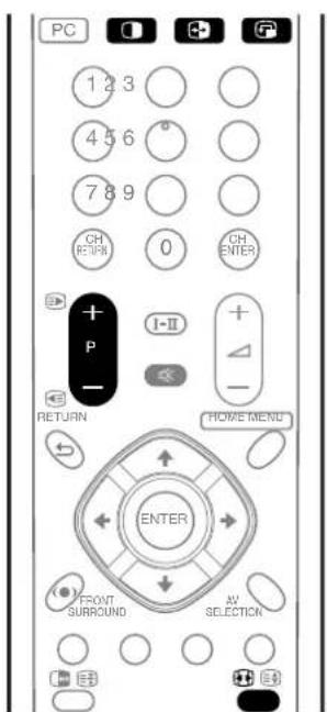
text_image
PC 1 2 3 4 5 6 ° 7 8 9 GH RETURN 0 CH ENTER + P I-II - RETURN HOME MEND ENTER FRONT SURROUND AV SELECTIONnatural_image
Black-and-white photo sequence showing a lakeside village with houses and mountains in the background, connected by an arrow indicating transformation (no text or symbols)
natural_image
Split black-and-white photo showing a city skyline on the left and a building complex on the right, both with no visible text or symbols.natural_image
Side-by-side comparison of urban buildings under cloudy sky, showing original and processed views with no visible text or symbols

natural_image
Black-and-white photo sequence showing a city skyline before and after transformation, with no visible text or symbols.text_image
1 2 3 4 5 6 7 8 9 0 A B C D E F G H J Delete K L M N O P Q R S T Space U V W X Y Z , . : ; & ' ( ) + - * / _ @ OKtext_image
Reponer FOCUS Apagado Surround frontal ApagadoÍtem Descripción
Apagado (valor predeterminado)
natural_image
Exterior view of a two-story house surrounded by trees (no signage or text visible)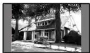
natural_image
Exterior view of a two-story house surrounded by trees and open ground (no signage or text visible)Media Receiver (vista trasera)
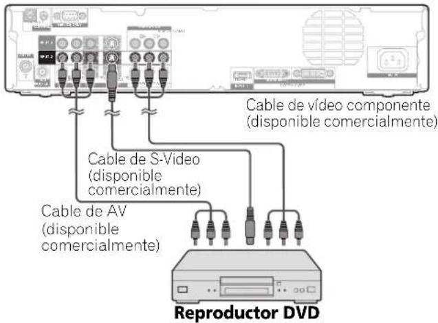
Media Receiver (vista trasera)
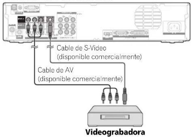
Media Receiver (vista trasera)
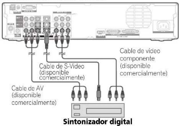
Media Receiver (vista frontal)
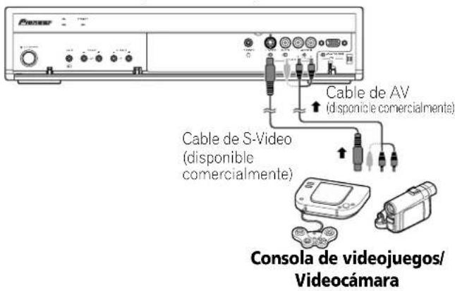
Media Receiver (vista frontal)
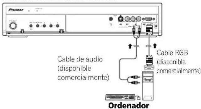
Media Receiver (vista trasera)

Media Receiver (vista trasera)
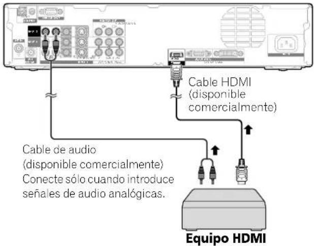
Media Receiver (vista trasera)

flowchart
graph TD
    A["Central Device"] --> B["Controller"]
    B --> C["Printer"]
    C --> D["Server"]
    A --> E["External Display"]
    E --> F["External Display"]
    style A fill:#f9f,stroke:#333
    style B fill:#ccf,stroke:#333
    style C fill:#cfc,stroke:#333
    style D fill:#fcc,stroke:#333
    style E fill:#cff,stroke:#333
    style F fill:#ffc,stroke:#333
Copyright © 2005 Pioneer Corporation.
(PDP-R06G) (PDP-R06G)
Controle remoto ....14
05 Preparação
natural_image
Simple line drawing of a folded paper or fabric (no text or symbols)Pano de limpeza

Ficha de garantía

Núcleo de ferrita

natural_image
Simple line drawing of a tool or bracket with a handle and base (no text or symbols)Atadura de cabo
Receiver de mídia

natural_image
Two cylindrical batteries with metallic leads, shown in grayscale (no text or symbols)
natural_image
Line drawing of a remote control with scroll and keypad (no text or symbols)
natural_image
Coiled electronic device with two connectors and a central connector (no text or symbols visible)natural_image
Simple 3D illustration of a blank rectangular block (no text or symbols)
NOTA
text_image
Diagram of a TV rear panel with labeled ports and connectors, showing internal layout and component placement.1 Botão POWER
2 Indicador STANDBY
3 Indicador POWER ON
4 Sensor do controle remoto
5 Terminais SPEAKER (direito/esquerdo)
6 Terminal SYSTEM CABLE (PRETO)
7 Terminal SYSTEM CABLE (BRANCO)
8 Terminal AC IN
Receiver de mídia
Vista frontal
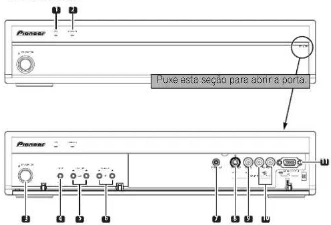
text_image
1 2 3 4 5 6 7 8 9 10 11 12 13 14 15 PIONEER PLASMA DISPLAY INPUT 1 2 3 4 PC 1 2 3 4 5 6 7 8 9 0 + - I-III OR ENTER 8LESTON SET SET SET SET SET SET SET SET SET SET SET SET SET SET SET SET SET SET SET SET SET SET SET SET SET SET SET SET SET SET SET SET SET SET SET SET SET SET SET SET SET SET SET SET SET SET SET1 ⏻
Liga o monitor de plasma ou coloca-o no modo de espera.
2 INPUT 1, 2, 3, 4
natural_image
Pure electrical circuit lines without any symbolsnatural_image
Technical line drawing of a mechanical component with mounting holes and a close-up inset showing a circular detail (no text or symbols)text_image
Diagram illustrating two mechanical or electrical setups with labeled components and directional arrows indicating motion or movement.text_image
SR 7 m 30° 30° Sensor do controle remototext_image
INPUT 1236 PC 1 45 76 0 SET OUTPUTtext_image
8 AAA ESTÉREO PADRÃO TOTALtext_image
Pioneer VOLUME +/-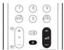
Ajuste de volume

text_image
28Emudecimento

text_image
OK 28Mudança dos canais
text_image
Tela principal Tela secundáriaImagem-em-imagem
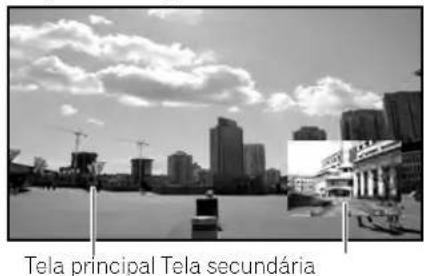
text_image
Tela principal Tela secundária
text_image
PC 1 2 3 4 5 6 7 8 9 CH RETURN 0 CH ENTER + P - I-II + - RETURN HOME MEND ENTER EFFECT SURROUND AV SELECTIONnatural_image
Black-and-white photo collage showing four scenes: a building with water, a waterfront, a building with mountains, and a city skyline (no visible text or symbols)natural_image
Four-panel black-and-white photo sequence showing city skyline changes under cloudy sky, with arrows indicating direction of movement (no text or symbols)text_image
1 2 3 4 5 6 7 8 9 0 A B C D E F G H K L M N O P Q R S T U V W X Y Z , , : & ' ( ) + - * / _ @ JDelete Space ; OKnatural_image
Exterior view of a two-story house surrounded by trees and a paved courtyard (no signage or text visible)
natural_image
Exterior view of a two-story house surrounded by trees (no signage or text visible)5 Pressione HOME MENU para sair do menu.
Copyright © 2005 Pioneer Corporation.
責任方:PIONEER ELECTRONICS SERVICE, INC.
natural_image
Simple line drawing of a folded paper or sheet with no text or symbols清潔布

保修卡
鐵氧體磁心

natural_image
Simple line drawing of a tool or bracket with a handle and base (no text or symbols)束線帶
媒體接收器

交流電源線 AA 型電池×2 遙控器

natural_image
Two cylindrical batteries with metallic leads, shown in black and white (no text or symbols)
natural_image
Line drawing of a remote control with standard buttons and dials (no text or symbols)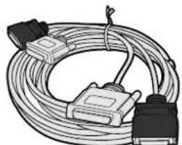
natural_image
Coiled cable with two connectors and a terminal connector (no text or symbols visible)系統連接線(3 米) 操作說明書

natural_image
Simple 3D illustration of a blank rectangular block (no text or symbols)
附注
text_image
Diagram of a TV rear panel with labeled ports and connectors, showing internal layout and component placement.1 POWER (電源)按鈕
2 STANDBY(待機)指示燈
3 POWER ON(打開電源)指示燈
4 遥控感知器
natural_image
Simple line drawing of a smartphone with two crossed X-shaped bars (no text or symbols)防止電漿電視翻覆
text_image
Technical diagram showing a mechanical or electrical component with labeled parts and an inset detail view highlighting a connection point.安裝和拆卸扎線扣
text_image
Diagram illustrating two mechanical or electrical setups with labeled components and directional arrows indicating movement or force.natural_image
Black-and-white photo of a lakeside house with trees and sailboats, no visible text or symbols主畫面
副畫面
子母畫面

natural_image
Black-and-white cityscape with modern high-rise buildings under construction and a bridge in the foreground (no visible text or signage)主畫面 副畫面

text_image
PC 1 2 3 4 5 6 7 8 9 CH RETURN I-II + - RETURN MOVE MENU ENTER FRONT SURROUND AV SELECTION1 按下 ☐ 按鈕選擇顯示模式。
natural_image
Black-and-white photo collage showing urban scenes with buildings and a waterfront, no visible text or symbolsnatural_image
Four-panel black-and-white photo sequence showing city skyline changes with arrows indicating direction of movement (no text or symbols)text_image
1 2 3 4 5 6 7 8 9 0 A B C D E F G H K L M N O P Q R S T U V W X Y Z , . : ; & ' ( ) + - * / _ @ Delete Space OK- 游標移動到第二個字元。
natural_image
Exterior view of a two-story house surrounded by trees and open ground (no signage or text visible)4:3
natural_image
Exterior view of a two-story house surrounded by trees (no signage or text visible)Published by Pioneer Corporation.
Copyright © 2005 Pioneer Corporation.
All rights reserved.
PIONEER CORPORATION
4-1, Meguro 1-Chome, Meguro-ku, Tokyo 153-8654, Japan
PIONEER ELECTRONICS (USA) INC.
P.O. BOX 1540, Long Beach, California 90810-1540, U.S.A. TEL: (800) 421-1404
PIONEER ELECTRONICS OF CANADA, INC.
300 Allstate Parkway, Markham, Ontario L3R OP2, Canada TEL: 1-877-283-5901
PIONEER EUROPE NV
Haven 1087, Keetberglaan 1, B-9120 Melsele, Belgium TEL: 03/570.05.11
PIONEER ELECTRONICS ASIACENTRE PTE. LTD.
253 Alexandra Road, #04-01, Singapore 159936 TEL: 65-6472-7555
PIONEER ELECTRONICS AUSTRALIA PTY. LTD.
178-184 Boundary Road, Braeside, Victoria 3195, Australia, TEL: (03) 9586-6300
PIONEER ELECTRONICS DE MEXICO S.A. DE C.V.
Blvd.Manuel Avila Camacho 138 10 piso Col.Lomas de Chapultepec, Mexico,D.F. 11000 TEL: 55-9178-4270
K002_A_En