
TD 2015 - Turntable THORENS - Free user manual and instructions
Find the device manual for free TD 2015 THORENS in PDF.

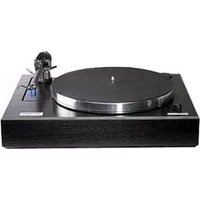
| Product type | Turntable |
| Brand | Thorens |
| Model | TD 2015 |
| Dimensions (W x D x H) | 420 x 330 x 140 mm |
| Weight | 11.0 kg |
| Power supply | PS 800 power supply unit with country-specific power adapter |
| Drive system | Belt drive (external) with electronic speed control, AC synchronous motor |
| Speeds | 33 1/3 and 45 rpm |
| Platter | 12 inches (30.5 cm) aluminum, 3.7 kg |
| Tone arm | Thorens TP 92 |
| Antiskating | Magnetic (adjustable) |
| Tracking force adjustment | Via counterweight, with supplied scale |
| VTA adjustment | Via adjustment nut under the turntable |
| Cable capacitance | 140 pF |
| Auto stop | No, manual stop |
| Manufacturing | Handmade in Germany |
| Maintenance and cleaning | Soft damp cloth (like eyeglass cleaning); avoid paper or rough cloths; use only original Thorens belts |
| Safety | Do not open the chassis; do not expose to rain or moisture; unplug before transport |
| Spare parts and repairability | Original belts and parts available from Thorens dealers |
| General information | Use with an amplifier equipped with a phono input or a phono preamplifier; keep minimum distance from other devices to avoid interference |
Frequently Asked Questions - TD 2015 THORENS
User questions about TD 2015 THORENS
0 question about this device. Answer the ones you know or ask your own.
Ask a new question about this device
Download the instructions for your Turntable in PDF format for free! Find your manual TD 2015 - THORENS and take your electronic device back in hand. On this page are published all the documents necessary for the use of your device. TD 2015 by THORENS.
USER MANUAL TD 2015 THORENS
THORENS®
TD 2015
TD 2035
Bedienungsanleitung
User Manual
Mode d'Emploi
www.thorens.com
TD 2015
TD 2035
Bedienungsanleitung
User Manual
Mode d'Emploi

Inhalt
EINLEITUNG 6
SICHERHEITSHINWEISE
AUSPACKEN UND MONTAGE 8
UNPACKING AND ASSEMBLY 24
PLACEMENT AND CONNECTIONS 26
TONEARM TP 92 28
TRACKING FORCE 29
ANTI-SKATING FORCE (BIAS) 30
FURTHER TONEARM ADJUSTMENTS 31
OPERATION 33
MAINTENANCE AND CARE 34
TECHNICAL SPECIFICATIONS 35
CUSTOMER SERVICE 36
Sommaire
2INTRODUCTION 38
CONSIGNES DE SECURITE 39
DEBALLAGE ET MONTAGE 40
INSTALLATION ET RACCORDEMENT 42
BRAS ET CELLULE DE LECTURE 44
FORCE D'APPUI 45
FORCE ANTISKATING 46
AUTRES REGLAGES DU BRAS DE LECTURE 47
UTILISATION DE LA PLATINE 49
MAINTENANCE ET ENTRETIEN 50
CARACTERISTIQUES TECHNIQUES 51
INFORMATIONS SERVICE APRES-VENTE 52
Einleitung
Sicherheitshinweise
BITTE VOR DER ERSTMALIGEN INBETRIEBNAHME AUFMERKSAM LESEN!
VORSICHT
Abb. 1

Abb. 2.1 Abb. 2.2


Abb. 2.3 Abb. 2.4
Auflagekraft

12" / 6,0 kg (Aluminium)
Thorens TP 92
magnetisch
keine
keine
140 pF
Congratulations on your purchase of the TD 2015/2035.
We hope that your new turntable will give you lots of listening pleasure. In combination with a good pick-up cartridge this turntable will yield outstanding sound. Manufacturing and assembly of this turntable are carried out in Germany, which will guarantee you that its high quality and functionality are maintained for many years to come.
Please keep in mind that this device is a precision instrument and therefore requires careful handling. We strongly advise you to read these instructions carefully before proceeding with the set-up as they contain all necessary information and guidance for assembly, placement, set-up and configuration of your new turntable.
Should you have any question that this user manual cannot answer, please do not hesitate to ask your Thorens dealer for further assistance.

Safety instructions
To reduce risk of electric shock, do not remove the cover (or back). No user-serviceable parts inside.
WARNING
TO PREVENT FIRE OR SHOCK HAZARD, DO NOT EXPOSE THIS APPLIANCE TO RAIN OR MOISTURE.

EXPLANATION OF GRAPHICAL SYMBOLS
The lightning flash with arrowhead symbol, within an equilateral triangle, is intended to alert you to the presence of uninsulated 'dangerous voltage' within the product's enclosure that may be of sufficient magnitude to constitute an electric shock to persons.

The exclamation point within an equilateral triangle is intended to alert you to the presence of important operating and maintenance (servicing) instructions in the literature accompanying the appliance.

This product was tested and complies with all the requirements for the CE Mark.
Compliant to 2002/95/EC (RoHS)

IMPORTANT: DISPOSAL OF WASTE EQUIPMENT BY USERS IN PRIVATE HOUSEHOLDS IN THE EUROPEAN UNION
This symbol on the product or on its packaging indicates that this product must not be disposed off with your other household waste. Instead, it is your responsibility to dispose of your waste equipment by handing it over to a designated collection point for the recycling of waste electrical and electronic equipment. The separate collection and recycling of your waste equipment at the time of disposal will help to conserve natural resources and ensure that it is recycled in a manner that protects human health and the environment. For more information about where you can drop off your waste equipment for recycling, please contact your local city office, your household waste disposal service or the shop where you purchased the product.
Unpacking and Assembly
Carefully remove the unit and its accessories from the shipping box.
Supplied items: 1 x plinth (with/without tonearm)
1 x tonearm counterweight (only with tonearm)
1 x motor in housing
1 x Thorens drive belt
1 x platter with felt mat
1 x electronic control unit PS 800
1 x mains adaptor
1 x power cord
1 x stylus balance
1 x adaptor for single records
3 x protective pads
2 x cotton glove
Attention: The surface of both plinth and platter is quite sensitive to scratches. It is therefore recommended that you wear the gloves supplied when assembling the turntable.
Proceed by placing the three protective pads where the turntable is eventually going to be. They are provided to prevent the sensitive surface of furniture from being damaged by the turntable's spiked feet.
Now put the feet of the turntable onto the pads and, after the final position has been achieved, make sure that the plinth is level. For any fine-adjustments turn the tip of each foot up or down until the plinth is in a perfect horizontal position. Use a spirit level to check for accuracy.
The motor housing is now inserted into the designated recess at the rear left corner. This is done by lifting the plinth and positioning the motor exactly beneath the recess. Lower the plinth slowly so that the motor housing enters the recess. Great care should be taken while doing this in order to prevent any scratches on the plinth surface. When in its final position the motor housing should not touch the inside of the recess.
Remove the bearing seal and gently insert the axle into the bearing, taking care to avoid any abrupt pressure on the bottom. Then turn the platter by hand to check that it runs smoothly and with ease. Put on the felt mat and loop the belt around the platter and the motor pulley. → Fig. 1
Avoid any oil or greasy substance getting onto the belt and the transmission area of platter and motor pulley. If necessary you may clean them with a lint-free tissue soaked in an alcoholic dilution.
Unless you have acquired your turntable with tonearm, you can now proceed by mounting the tone arm according to the instructions supplied by its manufacturer. Otherwise your turntable is now completely assembled.
It is highly recommended that you save the shipping box and all packing material in case the turntable needs to be packed again for transportation. Thorens will not assume liability for damage occurring during transit as a result of unsuitable packing.

Fig. 1
Placement and Connections
Connect the cord coming from the motor housing to the rear panel of the electronic control unit PS 800. → Fig. 2.1
Before connecting the turntable to the mains power please make sure that the power switch on the PS 800 unit is set to OFF and the speed selector switch set to "33". → Fig. 2.2
The PS 800 unit is connected to the mains by using the mains adaptor and the power cord plugged into a wall socket. → Fig. 2.3

Attention: Never disconnect the motor plug from the PS 800 unit while it is switched ON. Disregarding this advice may damage the electronic circuitry inside the PS 800.
Take the RCA interconnect leads ( → Fig. 2.4) and plug them into the designated (phono) input jacks at the rear side of your amplifier or receiver. Make sure that polarity (left/right channel!) is correct.


Fig. 2.1 Fig. 2.2

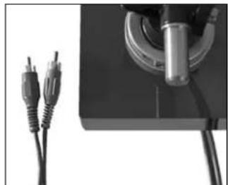
Fig. 2.3 Fig. 2.4
If your amplifier lacks a built-in phono stage you need to acquire a special external phono-preamplifier. For amplifiers/receivers featuring a 5-pin DIN-socket at the phono input section you will need a special adaptor (RCA to DIN) which may be available from your Thorens dealer.
When placing the turntable in its final position make sure that it is a fair distance away from other audio devices, such as amplifier, receiver or CD player. This measure will avoid electro-magnetic interference which can lead to a distorting effect in the sensitive pick-up cartridge, which may be audible as humming during playback.
Electro-magnetic interference, however, can be detected and eliminated by simply changing the position of the turntable with respect to the other devices.
Thorens turntables are relatively insensitive when subject to foot-fall shocks or airborne resonance. Nevertheless, a general problem remains when it comes to playing back vinyl records with a high-quality pick-up cartridge. It is therefore highly recommended to choose a sturdy piece of furniture for placement and to avoid the proximity of the turntable to the loudspeakers.
Under certain circumstances all these precautions may not be good enough in older houses with wooden floor construction. Here, in most cases, a solid shelf firmly mounted to a supporting wall can be very beneficial for the sonic properties of the turntable if it is placed on such a shelf or console.
Tonearm and Pick-Up Cartridge
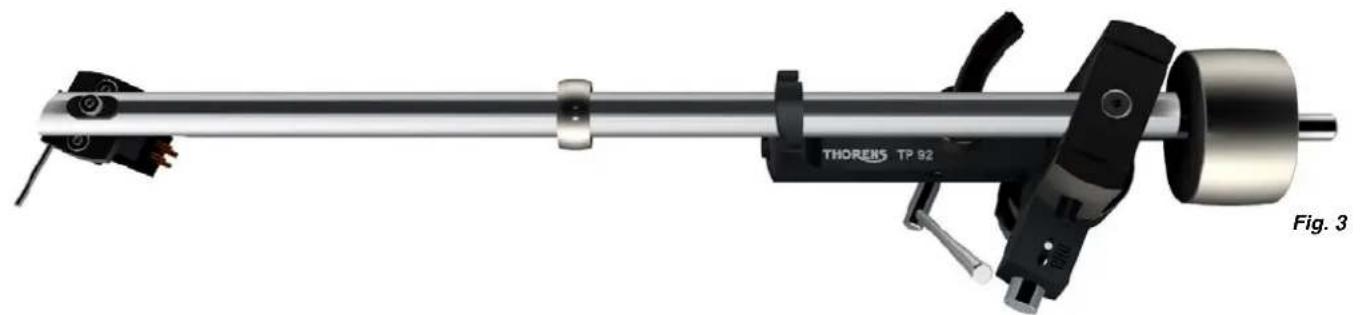
The following instructions apply only to turntables delivered with a pre-installed TP 92 tonearm. → Fig. 3
The tonearm counterweight has been removed for shipping. Screw the counterweight onto the rear end of the tonearm and adjust the tracking force. → Page 31
The TP 92 tonearm can accommodate most pick-up cartridges with a distance of 12.5 mm ( 1/2 ) between the mounting holes.
To connect the pick-up cartridge, push the four colour-coded cartridge tags onto the cartridge pins.
If the cartridge pins are not colour-coded, connect them as follows:
R right channel (signal) → red
G right channel (earth) → green
L left channel (signal) → white
G left channel (earth) → blue
Tracking Force
The tracking force can be adjusted by rotating the to-nearm counterweight ( → Fig. 4). The closer the counterweight is to the cartridge, the higher the tracking force.
The tracking force can be set with the help of the supplied stylus balance. Lower the tonearm lift, move the tonearm out over the platter and carefully lower it until the stylus of the pick-up cartridge comes to rest on the stylus balance. The stylus guard must be removed for this procedure.
Great care should be taken to avoid damaging the stylus.
Note: Refer to the user manual of your pick-up cartridge to determine the correct tracking force.

Do not move the ring that sits around the middle of the tonearm tube ( → Page 30, Fig. 3). It serves as a vibration damper and is effective only at its original position.
Anti-Skating Force (Bias)
The interaction of stylus friction and cartridge-bearing forces produces a force which pulls the tonearm towards the centre of the record (referred to as skating force). This force can be offset with the help of anti-skating force, which, in the case of the TP 92, is produced by a magnet incorporated into the tonearm.
The anti-skating force is factory-adjusted. If necessary, it can be readjusted with the help of an adjustment screw. → Fig. 5
Turn the adjustment screw anti-clockwise to increase, and clockwise to decrease the anti-skating force. The white dot above the adjustment screw indicates the setting.
The amount of anti-skating force required depends on the type of pick-up cartridge used. If you change the cartridge for a different type, use a test record to determine how much anti-skating force is required.

Further Tonearm Adjustments
The tonearm headshell allows an overhang adjustment of ± 2,5 mm to be made. To adjust overhang, loosen the screw holding the headshell and move the headshell as required. → Fig. 6
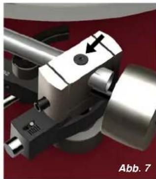
A screw at the rear of the tonearm allows a further overhang adjustment of ±3 mm as well as an azimuth adjustment of ±5° . The screw is recessed into the top of the bearing housing and can be loosened with a 2-mm hex key. → Fig. 7
The vertical tracking angle (VTA) can be adjusted by raising or lowering the tonearm. → Page 34
Take care not to over-tighten the screws after making adjustments.


Further Tonearm Adjustments
The vertical tracking angle (VTA) can be adjusted by raising or lowering the entire tonearm. Loosen the lock nut (TD 2015 → Fig. 8a) or the adapter screw (TD 2035 → Fig. 8b) on the underside of the turntable; then turn the adjustment ring above the base to raise or lower the tonearm as required.
If the VTA is changed, the tonearm lift will need to be to be readjusted. Loosen the locking screw on the tonearm lift with a 1.5-mm hex key and carefully raise or lower the entire lift. → Fig. 9
The tonearm tube should be parallel to the platter surface. Small adjustments of the VTA or the tonearm lift height can have a large effect. After making any changes, you should therefore always check whether there is enough clearance (at least 1 mm) between the cartridge and the record (when the lift is engaged) and between the tonearm lift pad and the tonearm tube (when the lift is disengaged).


Operation
The motor of the turntable is electronically controlled by the connected PS 800 unit ( → Fig. 10). The toggle switch on the right is for selecting the speed. Two speeds are available: 33 1/4 rpm for long playing records and 45 rpm for singles. The toggle switch on the left labelled ON/OFF is to start or stop the motor.
To play a record the turntable is first started at the speed desired. Then lift the tonearm by slowly pushing the lift lever up and back. Release the tonearm from its rest and position it above the lead-in groove or above the desired piece/track to be played. Slowly bring the lift lever to the down-position whereupon the tonearm descends smoothly.
This turntable does not feature any automatic end-of-record shut-off facility. Therefore, as soon as the stylus has reached the lead-out groove, the tonearm is to be lifted up manually by the lever and the motor switched off.

Fig. 10
Maintenance and Care
Your turntable requires no particular maintenance.
If, within the course of time, dust has collected on the plinth you can wipe it off with a moistened cloth. Tip: A pre-moistened cleaning tissue for glasses is a very good choice for doing this.
Do not use paper tissue or any coarse-fibred cloth because they may leave scratches on the rather sensitive acryl surface. Also refrain from using a dry cloth for cleaning because this could generate undesired static charges.
Use only original Thorens replacement belts as only these will ensure that your turntable operates as intended. Suitable replacement belts and other accessories are available from your Thorens dealer.
Technical Specifications
| Model | TD 2015 | TD 2035 |
| Drive system | Belt drive (via platter rim) | Belt drive (via platter rim) |
| Motor | Electronically controlled synchronous AC motor | Electronically controlled synchronous AC motor |
| Speed | 33 1⁄3 and 45 rpm | 33 1⁄3 and 45 rpm |
| Speed change | Electronic | Electronic |
| Platter | 12" / 3.7 kg (aluminium) | 12" / 6.0 kg (aluminium) |
| Tonearm (standard) | Thorens TP 92 | Thorens TP 92 |
| Anti-skating | Magnetic | Magnetic |
| Automatic functions | n/a | n/a |
| Automatic shut-off | n/a | n/a |
| Capacity of leads | 140 pF | 140 pF |
| Power supply | PS 800 electronic control unit country-specified mains adaptor | PS 800 electronic control unit country-specified mains adaptor |
| Dimensions | 420 x 330 x 140 mm (W x D x H) | 420 x 330 x 160 mm (W x D x H) |
| Weight | 11.0 kg | 15.0 kg |
Technical modifications subject to change. Handmade in Germany
Customer Service
Your Thorens dealer or distributor will be happy to assist you if you have any questions regarding your new turntable or experience any problems. For a list of Thorens distributors, please visit → www.thorens.com or contact us directly:
→ www.thorens.com/contact
Register your product with Thorens to receive up-to-date information and special offers. You can use the registration card included with the product or visit our website:
→ www.thorens.com/register
Notes
Introduction
Fig. 1
Installation et raccordement

Fig. 2.1 Fig. 2.2

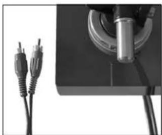
Fig. 2.3 Fig. 2.4
Force d'appui

→ www.thorens.com/contact
→ www.thorens.com/register
Notes
THORENS®
Copyright © 2013
Thorens Export Company AG


- THORENS®
- TD 2015
- TD 2035
- INHALT
- SOMMAIRE
- EINLEITUNG
- SICHERHEITSHINWEISE
- BITTE VOR DER ERSTMALIGEN INBETRIEBNAHME AUFMERKSAM LESEN
- VORSICHT
- AUFLAGEKRAFT
- 12" / 6,0 KG (ALUMINIUM)
- THORENS TP 92
- MAGNETISCH
- KEINE
- 140 PF
- CONGRATULATIONS ON YOUR PURCHASE OF THE TD 2015/2035
- SAFETY INSTRUCTIONS
- WARNING
- EXPLANATION OF GRAPHICAL SYMBOLS
- COMPLIANT TO 2002/95/EC (ROHS)
- IMPORTANT: DISPOSAL OF WASTE EQUIPMENT BY USERS IN PRIVATE HOUSEHOLDS IN THE EUROPEAN UNION
- UNPACKING AND ASSEMBLY
- PLACEMENT AND CONNECTIONS
- TONEARM AND PICK-UP CARTRIDGE
- TRACKING FORCE
- GREAT CARE SHOULD BE TAKEN TO AVOID DAMAGING THE STYLUS
- ANTI-SKATING FORCE (BIAS)
- FURTHER TONEARM ADJUSTMENTS
- OPERATION
- MAINTENANCE AND CARE
- TECHNICAL SPECIFICATIONS
- CUSTOMER SERVICE
- NOTES
- INTRODUCTION
- INSTALLATION ET RACCORDEMENT
- FORCE D'APPUI
Brand : THORENS
Model : TD 2015
Category : Turntable