HC-BM10 - Baby monitor KONIG - Free user manual and instructions
Find the device manual for free HC-BM10 KONIG in PDF.

User questions about HC-BM10 KONIG
0 question about this device. Answer the ones you know or ask your own.
Ask a new question about this device
Download the instructions for your Baby monitor in PDF format for free! Find your manual HC-BM10 - KONIG and take your electronic device back in hand. On this page are published all the documents necessary for the use of your device. HC-BM10 by KONIG.
USER MANUAL HC-BM10 KONIG
natural_image
Two blue and white electronic devices with earphones and a digital display (no visible text or symbols)MANUAL (p. 2)
Baby Monitor
ANLEITUNG (s. 8)
Baby Monitor
MODE D'EMPLOI (p. 14)
Baby Monitor
MANUAL DE USO (p. 32)
text_image
Labeled diagram of a mobile phone with numbered parts for identification
text_image
13 14 0 15- Antenna
- Alarm ON/OFF switch
- 6V DC jack
- Recharging base
- Power ON/OFF button
- Volume control
- Melody selection button
- Power ON/OFF indicator
- Sound level LEDs bar
- LCD display
- Speaker
- Recharging base power ON/OFF indicator
- PTT button
- Battery door
- Recharging base 6 V DC jack
PICTURE OF BABY UNIT

text_image
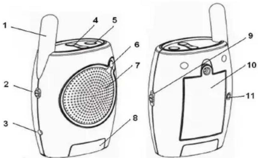
Technical diagram of a portable radio device with numbered parts for identification- Antenna
- High/Low transmission selection
- 6V DC jack
- Volume control
- Power ON/OFF button
- Power ON/OFF indicator
- Speaker
- Night light
- Night light control
- Battery door
- Matching (Pairing) button
SAFETY INSTRUCTIONS
Please observe the following precautions to prevent fire, personal injury, and product damage:
Read Instructions:
All the safety and operating instructions should be read before the baby monitor is operated.
Retain Instructions:
The safety and operating instructions should be retained for future reference.
Follow Instructions:
All operating instructions should be followed.
Water and Moisture:
This product is designed for indoor use only. The unit should not be exposed to dripping or splashing liquids and no objects filled with liquids, such as vases, should be placed on the unit. The item should not be used near water; for example, near a bath tub, wash bowl, kitchen sink, laundry tub, in a wet basement, near a swimming pool, etc.
Ventilation:
The baby monitor should not be situated on a bed, sofa, rug, or similar surface that may block the ventilation openings, or placed in an enclosed installation, such as a bookcase or cabinet that may impede the flow of air through the ventilation openings.
Heat:
The baby monitor should be situated away from heat sources such as radiators, heat registers, cookers, or other appliances that produce heat. No naked flame sources, such as lighted candles, should be placed on the device.
Power Source:
The baby monitor should be connected to a power supply only of the type described in this operating instruction: Baby and Parent Units: AC/DC adaptors: 6 V 400 mA (centre positive)
Cleaning:
Use a dry cotton cloth to keep the baby monitor free of dust. Do not use water!
Non-Use Periods:
Always unplug the AC adaptors from the wall outlets during long periods of non-use.
Caution:
a. This product cannot replace responsible adult supervision of a child. You should personally check your child's activity at regular intervals.
b. Never use this baby monitor to a degree where your life or health, the life or health of others, or integrity of property depends on its function! The manufacturer will not accept any responsibility or claim for death and injury of any person or for loss and damage of any property due to malfunction or misuse of the product.
STATEMENT ON REGULATION
These limits are designed to provide reasonable protection against harmful interference in a residential installation. This equipment generates, uses and can radiate radio frequency energy and if not installed and used in accordance with the instructions, may cause harmful interference to radio communications. However, there is no guarantee that interference will not occur in a particular installation. If this equipment does cause harmful interference to radio or television reception, which can be determined by turning the equipment off and on, the user is encouraged to try to correct the interference by one or more of the following measures:
- Reorient or relocate the receiving antenna.
- Increase the distance between the equipment and receiver.
- Connect the equipment into an outlet on a circuit different from that to which the receiver is connected.
- Consult the dealer or an experienced radio/TV technician for help.
Operation with non-approved equipment or unshielded cables is likely to result in interference to radio or TV reception. The user is cautioned that changes and modifications made to the equipment without the approval of the manufacturer could void the user's authority to operate this equipment.
INSTALLATION
INSTALLING THE AC/DC ADAPTER:
- Install the plug of the AC adapter to the DC jack of the unit.
- Plug the AC adapter into a standard wall AC power outlet.
- Switch on the unit with the power ON/OFF switch.
- The power indicator will be illuminated.
Warning: Only use the AC adaptors supplied with the package. Improper use of the adapter may cause malfunction of the units. Please consult your dealer for any queries.
USING THE BATTERIES:
- The parent unit requires a 3x AAA size rechargeable battery pack to operate.
- One 3x AAA size rechargeable battery pack is supplied with the package. Use the rechargeable battery to operate the parent unit away from the remote location. Reconnect the parent unit to the adapter or place it on the charging base whenever possible to maintain the portable operation function.
- If you require another rechargeable battery pack for the parent unit please contact your certified local product supplier.
CHARGING THE BATTERIES:
- When the batteries are flat, the LEDs on both the parent unit and baby unit turn orange.
- Please note the parent unit has a recharging function while the baby unit is NON-RECHARGEABLE. Put the parent unit on the charging base to charge the batteries. The battery symbol on the LCD display will flash until it is fully charged. The LED on the charging base remains green, indicating Power On only. Similarly, the LED on the Parent unit stays green during charging.
BABY UNIT OPERATION
Power ON/OFF
Use the Power ON/OFF switch at the top of Baby unit to turn the unit ON/OFF. The power ON/OFF indicator (LED) will be turned ON/OFF accordingly.
High-Low Transmission
Select High or Low power transmission by using the HI / LO switch at the side of the Baby unit.
High power transmission provides the maximum communication range with the Parent unit.
Low power transmission provides an approximately 100 meters communication range with the Parent unit.
Volume Control
Press the (+) and (-) button located on the top of the Baby unit to increase and decrease the volume of the Baby unit.
Voice Activated (VOX) Function
When the sound level of the unit's surrounding area reaches the preset level, the Baby unit will transmit the captured sound to the Parent unit.
When the surrounding sound level is below the preset level, transmission will be automatically switched off and the speaker on the Parent unit will also be switched off.
Night Light
Switch to ON or OFF by sliding the OFF/AUTO/ON switch at the side of the Baby unit. The night light will be illuminated continuously at the base of the Baby unit.
Use Voice Activated Night Light (AUTO) by sliding the OFF/AUTO/ON switch to AUTO.
When the sound level of the unit's surrounding area reaches the preset level, the night light will be turned on.
When the surrounding sound level is below the preset level, the night light will be turned off.
Use the Power ON/OFF switch at the top of Parent unit to turn the unit ON/OFF. The power ON/OFF indicator (LED) and LCD will be turned ON/OFF accordingly.
Volume Control
Press the (+) and (-) button located on top of the Parent unit to increase and decrease the volume of the Parent unit. The corresponding volume level will be shown on the LCD volume level display. The 4 x LEDs sound bar above the LCD display will also light up to indicate the strength of the sound level.
Melodies (Lullabies) Selection and Transmission
Press the Melody Selection Button at the top of the Parent unit to select the melody to be sent to the Baby unit. The LCD will display L1 to L3 to indicate your selection.
The melody you selected will be transmitted to the Baby unit.
PTT (Push-to-Talk)
To talk to the Baby unit, press and hold the PTT button located on the side of the Parent unit and talk closely to the microphone of the Parent unit.
Out of Range Alarm
When the Parent unit cannot receive a transmission signal from the Baby unit, the audio Out of Range Alarm (continuous beep sound) will be set off, and 'NO SIGNAL' will also appear on the LCD display.
Baby's Room Temperature Indicated on Parent Unit
The Baby unit can detect the baby's room temperature and transmit the signal to the Parent unit. The temperature reading is indicated on the LCD of the Parent unit. Choose ^ or ^ on the selection switch located under the rechargeable battery pack on the Parent unit.
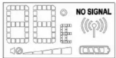
LCD DISPLAY
The LCD on the Parent unit displays:
1) Temperature in the baby's room.
Choose °C or °F display on the selection switch located under the rechargeable battery pack on the Parent unit.
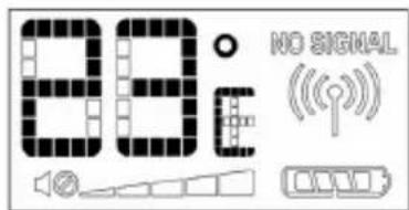
text_image
88:0 NO SIGNAL2) Volume level of the Parent unit.
5-volume strength levels
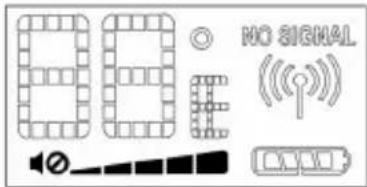
text_image
88 NO SIGNAL ((3) Battery capacity of the Parent unit.
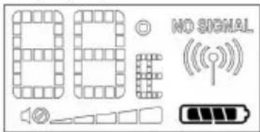
4) Connection between Parent and Baby units.
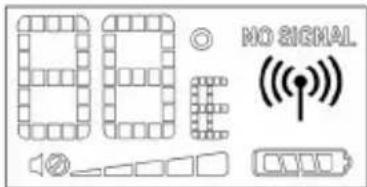
text_image
86 NO SIGNAL ((p))5) Out of range indicator.

text_image
NO SIGNALMATCHING (PAIRING)
WARNING!!
This product has already been matched (paired) in production and users DO NOT NEED to perform any matching procedure under normal conditions. Follow these steps to re-match the Parent unit with the Baby unit only when it is ABSOLUTELY NECESSARY:
-
Turn both the Parent and Baby units ON.
-
Press the CODE Button (11) located at the back of the Baby unit, the LED turns orange and flashes, and then press the CODE Button located on the lower right-hand corner inside the battery compartment of the Parent unit for 3 seconds. The LED of the Parent unit also turns orange and flashes. The two units now pair automatically. When pairing is successful, the LEDs will turn back to green.
TROUBLESHOOTING
| Problem Possible Cause – things to do/check | |
| No reception or transmission on the Parent unit. | The unit has not been switched on.The AC/DC adaptor has not been connected.The rechargeable battery pack is not installed properly.Battery power is low. Recharge the battery with the AC/DC adaptor or put it back to the charging base.The Baby unit may not be transmitting. |
| No reception or transmission on the Baby unit. | The unit has not been switched on.The AC/DC adaptor has not been connected.The volume level is set to lowest. Adjust volume switch. |
| The Night Light does not turn on. | The Night Light switch is not set properly.Switch the Night Light control to either ON or AUTO. |
Safety precautions:


To reduce risk of electric shock, this product should ONLY be opened by an authorized technician when service is required. Disconnect the product from mains and other equipment if a problem should occur. Do not expose the
product to water or moisture.
Maintenance:
Clean only with a dry cloth. Do not use cleaning solvents or abrasives.
Warranty:
No guarantee or liability can be accepted for any changes and modifications of the product or damage caused due to incorrect use of this product.
General:
Designs and specifications are subject to change without notice.
All logos brands and product names are trademarks or registered trademarks of their respective holders and are hereby recognized as such.
Keep this manual for future reference.
Attention:

This product is marked with this symbol. It means that used electrical and electronic products should not be mixed with general household waste. There is a separate collections system for these products.
DEUTSCH
text_image
Labeled diagram of a mobile phone with numbered parts for identification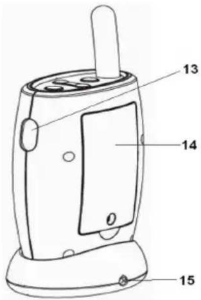
text_image
13 14 0 15text_image
Technical diagram of a portable radio device with numbered parts for identificationtext_image
Labeled diagram of a mobile phone with numbered parts for identification
text_image
13 14 0 15text_image
Technical diagram of a portable radio device with numbered parts for identificationPTT (Push-to-Talk) (fonction intercom)
text_image
Labeled diagram of a mobile phone with numbered parts for identification
text_image
13 14 0 15- Antenne
- Alarm AAN/UIT schakelaar
- 6 V DC connector
- Oplaadbasis
- AAN/UIT Knop
- Volumeknop
- Knop melodiekeuze
- AAN/UIT indicator
- Geluidsniveau LEDs balk
- LCD display
- Luidspreker
- Oplaadbasis AAN/UIT indicator
- PTT knop
- Batterijklepje
- Oplaadbasis 6 V DC connector
AFBEELDING VAN BABY UNIT

text_image
Technical diagram of a portable radio device with numbered parts for identificationtext_image
00 NO SIGNAL ((p))5) Indicator buiten bereik.
text_image
NO SIGNALPAREN
WAARSCHUWING!!
text_image
Labeled diagram of a mobile phone with numbered parts for identification
text_image
13 14 0 15text_image
Technical diagram of a portable radio device with numbered parts for identificationtext_image
Labeled diagram of a mobile phone with numbered parts for identification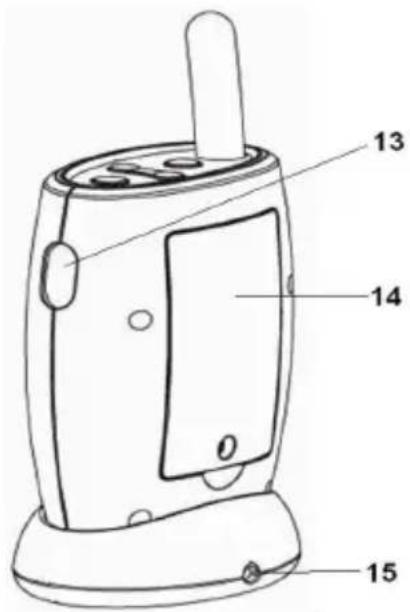
text_image
13 14 0 15text_image
Technical diagram of a portable radio device with numbered parts for identificationCOINCIDENCIA (PAREAMIENTO)
¡ADVERTENCIA!
text_image
Labeled diagram of a mobile phone with numbered parts for identification
text_image
13 14 0 15text_image
Technical diagram of a portable radio device with numbered parts for identificationtext_image
00 NO SIGNAL ((p))text_image
Labeled diagram of a mobile phone with numbered parts for identification
text_image
13 14 0 15text_image
Technical diagram of a portable radio device with numbered parts for identificationtext_image
800 © NO SIGNAL ((p))text_image
Labeled diagram of a mobile phone with numbered parts for identification
text_image
13 14 0 15text_image
Technical diagram of a portable radio device with numbered parts for identificationtext_image
Labeled diagram of a mobile phone with numbered parts for identification
text_image
13 14 0 15text_image
Technical diagram of a portable radio device with numbered parts for identificationtext_image
Labeled diagram of a mobile phone with numbered parts for identification
text_image
13 14 0 15text_image
Technical diagram of a device with numbered parts, showing front and side views of a speaker or radio.text_image
Labeled diagram of a mobile phone with numbered parts for identification
text_image
13 14 0 15text_image
Technical diagram of a portable radio device with numbered parts for identificationPTT (Λειτουργία Push-to-Talk)
text_image
Labeled diagram of a mobile phone with numbered parts for identification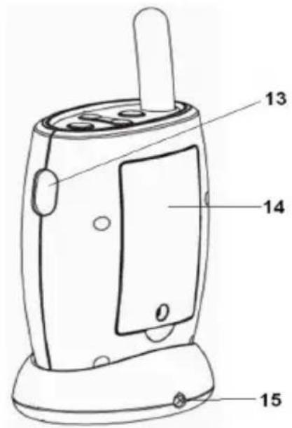
text_image
13 14 0 15text_image
Technical diagram of a portable radio device with numbered parts for identificationHøj-lav transmission
PTT (tryk for at tale)
text_image
Labeled diagram of a mobile phone with numbered parts for identification
text_image
13 14 0 15- Antenne
- Alarm PÅ/AV-bryter
- 6V DC-plugg
- Ladebase
- Strøm PÅ/AV-knapp
- Volumkontroll
- Knapp for melodivalg
- Strøm PÅ/AV-indikator
- Lydnivå, LED-stolpe
- LCD-display
- Høyttaler
- Ladebases strøm, PÅ/AV-indikator
- PTT-knapp
- Batteriluke
- Ladebases 6V DC-plugg
BILDE AV BABYENHET
text_image
Technical diagram of a portable radio device with numbered parts for identification- Antenne
- Høy/lav, sendingsvalg
- 6V DC-plugg
- Volumkontroll
- Strøm PÅ/AV-knapp
- Strøm PÅ/AV-indikator
- Høyttaler
- Nattlys
- Nattlyskontroll
- Batteriluke
- Koblings-/Paringsknapp