Zoe - Coffee machine Sanremo - Free user manual and instructions
Find the device manual for free Zoe Sanremo in PDF.

User questions about Zoe Sanremo
0 question about this device. Answer the ones you know or ask your own.
Ask a new question about this device
Download the instructions for your Coffee machine in PDF format for free! Find your manual Zoe - Sanremo and take your electronic device back in hand. On this page are published all the documents necessary for the use of your device. Zoe by Sanremo.
USER MANUAL Zoe Sanremo
natural_image
Close-up of a person in a spacesuit with equipment, no visible text or symbols
natural_image
Industrial machine with visible internal components and mechanical arms (no text or symbols)
natural_image
Close-up of a mechanical component with metallic parts, possibly a tool or device (no visible text or symbols)ZOE
Instruction Booklet
Bedienungsanleitung
Livret D'Instructions
natural_image
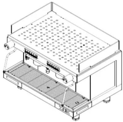
Technical line drawing of a rectangular electronic device with internal components and a 3D coordinate system (X, Y, Z axes) shown in the corner.| GRUPPI | 2 | |
| LARGHEZZA (X) mm 720 | ||
| PROFONDITA' (Y) mm 528 | ||
| ALTEZZA (Z) mm 537 | ||
| CAPACITA' litri 10 | ||
| PESO NETTO Kg 62,7 | ||
| PESO LORDO Kg 65 | ||
| TENSIONE DI ALIMENTAZIONE V | 120220-240 1N~380-415 3N~ | |
| POTENZA ASSORBITA DALLA RESISTENZA (230V) | kW | 2,95/4,9 |
| POTENZA ASSORBITA DALLA RESISTENZA SCALDATAZZE (optional) | kW | 0,2 |
| POTENZA ASSORBITA DALL'ELETTROPOMPA | kW | 0,2 |
| POTENZA ASSORBITA DALL'ELETTROPOMPA ESTERNA | kW | 0,2 |
| POTENZA ASSORBITA DALLE ELETTROVALVOLE | kW | 0,0225 |
| POTENZA ASSORBITA DAL REGOLATORE AUTOM. DI LIVELLO | kW | 0,01 |
| PRESSIONE DI ESERCIZIO CALDAIA | (0,8-1 Bar) MPa | 0,08:0,1 |
| PRESSIONE ACQUA RETE IDRICA (MAX) | (6 Bar) MPa | 0,6 |
| PRESSIONE DI EROGAZIONE CAFFE' | (8-9 Bar) MPa | 0,8/0,9 |
natural_image
Technical line drawing of a mechanical assembly with three views (top, front, side), showing components like a cylindrical tank and connected tubing (no text or labels)USO CONTROLLO PRELIMINARE
natural_image
Technical line drawing of a mechanical component with a circular outline (no text or symbols)natural_image
Technical line drawings of mechanical components and assemblies (no text or symbols)2) QUALITA' DELL'ACQUA
text_image
Technical schematic diagram of a fluid or pneumatic system with numbered components and piping connectionsVarianti
LEGENDA
text_image
Exploded view diagram of a device with numbered components and internal parts, likely for assembly or manufacturing purposes.ESPLOSO MOD. ZOE Agg. 03/12
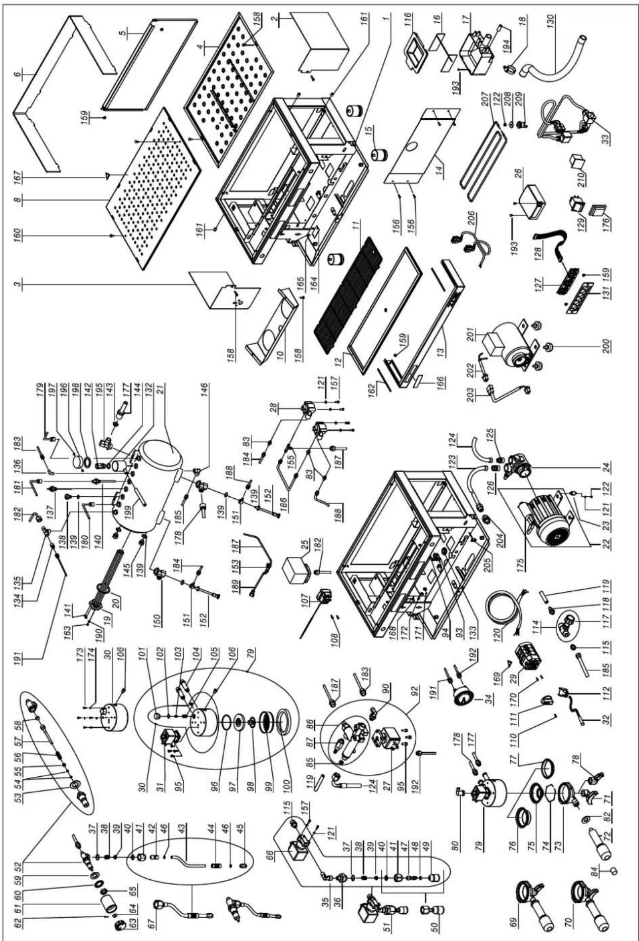
LEGENDA ESPLOSO ZOE SAP - SED AGG.03-12
| POS. COD. DESCRIZIONE | ||
| 1A 100 | 17302 TELAIO | ZOE 2GR NERO OPACO |
| 1B 100 | 17304 TELAIO | ZOE 2GR BIANCO |
| 2A 100 | 17372 PANNELLO | DX ZOE NERO LUCIDO |
| 2B 100 | 17374 PANNELLO | DX ZOE ROSSO |
| 2C 100 | 17376 PANNELLO | DX ZOE VIOLA PORPORA |
| 2D 100 | 17378 PANNELLO | DX ZOE NERO OPACO |
| 2E 100 | 17380 PANNELLO | DX ZOE BIANCO PERLA |
| 2F 100 | 17382 PANNELLO | DX ZOE GIALLO |
| 2G 100 | 17384 PANNELLO | DX ZOE VERDE |
| 3A 100 | 17392 PANNELLO | DX ZOE NERO LUCIDO |
| 3B 100 | 17394 PANNELLO | DX ZOE ROSSO |
| 3C 100 | 17396 PANNELLO | DX ZOE VIOLA PORPORA |
| 3D 100 | 17398 PANNELLO | DX ZOE NERO OPACO |
| 3E 100 | 17400 PANNELLO | DX ZOE BIANCO PERLA |
| 3F 100 | 17402 PANNELLO | DX ZOE GIALLO |
| 3G 100 | 17404 PANNELLO | DX ZOE VERDE |
| 4 100 | 17324 VASCA SUP. | ZOE 2GR ST. |
| 5A 100 | 17332 PANNELLO | POS.ZOE 2GR NERO LUCIDO |
| 5B 100 | 17334 PANNELLO | POS.ZOE 2GR ROSSO |
| 5C 100 | 17336 PANNELLO | POS.ZOE 2GR VIOLA PORPORA |
| 5D 100 | 17338 PANNELLO | POS.ZOE 2GR NERO OPACO |
| 5E 100 | 17340 PANNELLO | POS.ZOE 2GR BIANCO PERLA |
| 5F 100 | 17342 PANNELLO | POS.ZOE 2GR GIALLO |
| 5G 100 | 17344 PANNELLO | POS.ZOE 2GR VERDE |
| 6 103 | 52430 FERMATAZZE | ZOE 2GR TRASPARENTE |
| 8 100 | 17326 GRIGLIA | SUP. ZOE 2GR |
| 10A 100 | 17352 PROTEZ. | GRUPPI ZOE 2 NERO LUCIDO |
| 10B 100 | 17354 PROTEZ. | GRUPPI ZOE 2 ROSSO |
| 10C 100 | 17356 PROTEZ. | GRUPPI ZOE 2 VIOLA PORPORA |
| 10D 100 | 17358 PROTEZ. | GRUPPI ZOE 2 NERO OPACO |
| 10E 100 | 17360 PROTEZ. | GRUPPI ZOE 2 BIANCO PERLA |
| 10F 100 | 17362 PROTEZ. | GRUPPI ZOE 2 GIALLO |
| 10G 100 | 17364 PROTEZ. | GRUPPI ZOE 2 VERDE |
| 11 100 | 17328A GRIGLIA | SCARICO ZOE 2GR FILINOX |
| 12 100 | 17322 PIATTO | SCARICO ZOE 2GR |
| 13A 100 | 17472 FRONTALE INF. | ZOE 2GR NERO OPACO |
| 13B 100 | 17474 FRONTALE INF. | ZOE 2GR BIANCO |
| 14 100 | 17320 PROTEZ | ONE FRONT. ZOE 2GR |
| 15 103 | 52065 PIEDINO | D50X55 INOX TELESCOPICO |
| 16 100 | 12144 ROMPIGETTO PER VASCHETTA SCARICO | |
| 17 100 | 22441 VASCHETTA SCARICO UNIVERSALE | |
| 18 108 | 06099 FASCETTA INOX STRINGITUBO | |
| 19A 104 | 455050 RESISTENZA 1950W 230V 1GR | |
| 19B 104 | 455051 | RESISTENZA 1950W 120V 1GR |
| 19C 104 | 455052 RESISTENZA 2700W 230V 2GR | |
| 19D 104 | 455053 RESISTENZA 2700W 120V 2GR | |
| 19E 104 | 455054 RESISTENZA 5100W 230V 3GR | |
| 19F 104 | 455060 RESISTENZA 2400W 230V 1GR | |
| 19G 104 | 455065 RESISTENZA 2400W 120V 1GR | |
| 19H 104 | 455080 RESISTENZA 4500W 230V 2GR | |
| 20 105 | 02020 | RONDELLA PTFE D56X41X2mm |
| 21 100 | 02670 | CALDAIA RAME 2GR LITRI 10 D.190 |
| 22A 102 | 252079A MOTORE EL.150W 120V 1-2GR | |
| 22B 102 | 252080A MOTORE EL.150W 230V 1-2GR | |
| 22C 102 | 252086 MOTORE EL.165W 230V 2-3GR | |
| 22D 102 | 252094 MOTORE EL.150W 230V CB 2-3GR | |
| 22E 102 | 252098 MOTORE EL.130W 230V CB VENTILATO 1-2GR | |
| 23 102 | 55022 ANTIVIBRANTE PUFFER | |
| 24A 102 | 252070B POMPA ROTATIVA 150L/H 1-2GR | |
| 24B 102 | 252072B POMPA ROTATIVA 204L/H 2-3GR | |
| 25 106 | 02010A PRESSOSTATO | |
| 26A 101 | 12012 CENTRALINA XLC SED 120V | |
| 26B 101 | 12072E CENTRALINA XLC SED 230V |
| 26C 101 | 12083C CENTRALINA ON-OFF 1-2-3GR XLC |
| 27 103 | 03093A ELETTR. 2VIE BAS.32X32 230V |
| 28 101 | 12134 CONTATORE VOLUMETRICO 1/8" |
| 29A 101 | 122050 COMMUTATORE PONT. MONOFASE |
| 29B 101 | 122060 COMMUTATORE PONT. TRIFASE |
| 30 100 | 52028A GRUP. EROGAZ. ANELLO C/DOCCETTA E GUARN. E61 |
| 31A 103 | 02066 ELETTROV. 3VIE BAS.32X32 230V |
| 31B 103 | 05555 ELETTROV. 3VIE BAS.32X32 120V |
| 32A 105 | 53021 SPIA ARANCIO D6 230V CABLATA |
| 32B 105 | 53024 SPIA ARANCIO D6 120V CABLATA |
| 33A 101 | 02560 CABLAGGIO ZOE 2GR SED C/GR.ANELLO |
| 33B 101 | 02570 CABLAGGIO ZOE 2GR SAP C/GR.ANELLO |
| 34 105 | 52018 MANOMETRO |
| 35 108 | 52210 2020 RACCORDO AD L 1/8" F/M |
| 36 108 | 59029 RIDUZIONE 1/8"M 3/8"M CROMATA MI |
| 37 104 | 02056A OR 2062 VITON |
| 38 104 | 02043 MOLLA SNODO |
| 39 104 | 02054 SCODELLINO SNODO |
| 40 104 | 02082 OR SNODO LANCI A D10 |
| 41 104 | 02282 DADO LANCI A VAPORE MLX |
| 42 104 | 02288 SNODO A SFERA LANCI A MLX |
| 43 104 | 02274 TUBO VAP.BRILL.INOX LANCI A VAP.RM |
| 44 107 | 53052 GOMMINO ANTISCOTTURA |
| 45A 104 | 02276 TROMBONCINO INOX 2 FORI LATERALI |
| 45B 104 | 02279 TROMBONCINO INOX 4 FORI |
| 46 104 | 02081 OR TUBO LANCI A MLX |
| 47 104 | 02266 SNODO A SFERA INOX ACQUA 1/8"M |
| 48 105 | 05018 OR D.7,2X1,9 EPDM OR6 DOCCIA ACQUA |
| 49 104 | 02140 DOCCIA EROGAZIONE |
| 50 104 | 02143 DOCCIA CORTA EROGAZ. ACQUA COMPL. |
| 51 104 | 01982 RUBINETTO H2O COMPL. ZOE 230V |
| 52 104 | 02120A CORPO RUBINETTO |
| 53 105 | 05561 BUSSOLA RAME RUBINETTO |
| 54 105 | 05121 OR NBR ASTA RUBINETTO |
| 55 104 | 02015 BUSSOLA ASTA RUBINETTO |
| 56 104 | 02014 MOLLA ASTA RUBINETTO |
| 57 104 | 02061 ASTA CENTRALE RUBINETTO |
| 58 105 | 05558 GUARNIZ. TENUTA ASTA RUBINETTO |
| 59 108 | 03547 RONDELLA D20 ZN PIANA |
| 60 108 | 06312 RONDELLA D21 DENT. ZN |
| 61 100 | 92164A MANOPOLA VAPORE ROMA |
| 62 108 | 06370B COPPIGLIA RUBINETTO |
| 63 100 | 92162A TAPPO MANOPOLA VAPORE ROMA |
| 64 104 | 02040 RONDELLA OTT. RUBINETTO |
| 65 104 | 02028 MEZZO DADO 1/2" RIALZATO CR. |
| 66A 103 | 03060A ELETTR. 2VIE 1/8" 120V UL-CSA |
| 66B 103 | 03086 ELETTR. 2VIE 1/8"230V |
| 67 104 | 02484A LANCI A VAPORE COMPLETA RM-VM-ZOE D.10 |
| 69 104 | 02310C ASS.PORTAFILTRO 1 TAZZA 1,3 |
| 70 104 | 02312B ASS.PORTAFILTRO 2 TAZZE 1,3 |
| 71 100 | 52085 BECCUCCIO 2 VIE APERTO |
| 72 100 | 91150 MANOPOLA PORTAFILTRO VR-RM |
| 73 100 | 52034 CORPO PORTA FILTRO |
| 74 100 | 52055 MOLLA FERMA FILTRO 1,3 |
| 75A 100 | 52100 FILTRO 1 TAZZA |
| 75B 100 | 52101 FILTRO 1 TAZZA 6GR MOD. CIALDE |
| 76 100 | 52110 FILTRO 2 TAZZE |
| 77 100 | 52220 FILTRO CIECO |
| 78 100 | 52075 BECCUCCIO 1 VIA APERTO |
| 79A 100 | 52206A ASS. GRUPPO ANELLO CA GDE61 230V |
| 79B 100 | 52208A ASS. GRUPPO ANELLO CA GDE61 120V |
| 80 102 | 55028A RACCORDO GOMITO GIR.F1/8 |
| 81 108 | 52030A 1020 6-1/8"M RACC. GOMITO |
| 82 100 | 91154 ANELLO MANICO PORTAFILTRO VR-RM |
| 83 10852080A 1050 6-1/8"M RACC. DRITTO |
| 84 10091152 TAPPO MANICO PORTAFILTRO VR-RM |
| 85 10355172 FILTRO RETE TONDO |
| 86 10056058A CORPO MASSELLO CARICO LIGHT |
| 87 10655557 VALVOLA ESPANSIONE |
| 90 10255058 RACCORDO GOMITO GIREVOLE 1/8M |
| 92 10056110 ASS. MASSELLO CARICO 230V LIGHT |
| 93 10105022 PRESSACAVO PA268 |
| 94 10105024 VITE TC + 3,5X25 ZN PRESSACAVO |
| 95 10805071 VITE TCEI M4X10 A2 |
| 96 10502070A OR 3187 EPDM FDA |
| 97 10052248 MAZZOCCO GRUPPO ANELLO X GUARN. E DOCC. E61 |
| 98 10052141 DIFFUSORE GRUPPO E61 |
| 99 10052120 DOCCETTA A RETE GRUPPO E61 |
| 100 10502110 GUARN SOTTOC. GRUPPO E61 |
| 101 10052142 TAPPO CHIUS. GIGLEUR GR.ANELLO |
| 102 10052143 GUARN TAPPO SUP. GR. ANELLO |
| 103 10052135 GIGLEUR GRUPPI FORO D.0,8 |
| 104 10852033 PROLUNGA NI CA GR.ANELLO |
| 105 10052136 FILTRO GRUPPO E-61/ANELLO |
| 106 10805078 VITE TCEI M6X8 A2 |
| 107 10111015 TERMOSTATO A RIARMO MANUALE |
| 108 10805872 VITE TO + M4X6 ZN |
| 110 10805116 VITE TC + M3X10 TRUC. ZN NERA MANOP. COMMUTAT. |
| 111 10122015 MANOPOLA PER COMMUTATORE |
| 112 10105190 BLOCCHETTO 2 VIE F. |
| 114 10402059 RUBINETTO SCARICO C/MANOPOLA |
| 115 10852050A 1050 8-1/8"M RACC. DRITTO |
| 116 10022476 COPERCHIO VASCHETTA SCARICO |
| 117 10402060 MANOPOLA RUB.SCARICO CALDAIA |
| 118 10853058 1510 RACC.DRITTO PORT/GOM 6-1/8"M |
| 119 10905010 TUBO SILICONE TRASP. |
| 120A 10102190 CAVO ALIM. 3X2,5 MT3 N5 MONOFASE |
| 120B 10102191 CAVO ALIM. 5X2,5 MT3 N4 TRIFASE |
| 120C 10102193 CAVO ALIM. 3X4 MT3 N7 |
| 120D 10102196 CAVO ALIM. 3x12AWG SJOOW 3MT |
| 120E 10102197 CAVO ALIM. 3x14AWG SJOOW |
| 121 10803519 RONDELLA D4,2 DENT.ZN |
| 122 10805512 DADO 4MA MEDIO ZN |
| 123 10852484 TUBO TRAZIONE L=2000 |
| 124 10852470 TUBO TRAZIONE L=450 |
| 125 10852290A 1050 10-3/8"M RACC.DRITTO |
| 126 10852293A 1050 8-3/8"M RACC.DRITTO |
| 127A 10112268 PULSANTIERA TO 6 TASTI SED |
| 127B 10112274 PULSANTIERA TO 2 TASTI SAP |
| 128A 10112078 CAVO PIN TO PIN 600mm |
| 128B 10112079 CAVO PIN TO PIN 800mm |
| 129 10556041A INTERRUTTORE ROSSO SCALDATAZZE |
| 130 10852460 TUBO SPIRALATO SCARICO L.2 MT |
| 131A 10017412 SUPPORTO PULSANTIERA SED ZOE NERO |
| 131B 10017414 SUPPORTO PULSANTIERA SED ZOE BIANCO |
| 131C 10017432 SUPPORTO PULSANTIERA SAP ZOE NERO |
| 131D 10017434 SUPPORTO PULSANTIERA SAP ZOE BIANCO |
| 132 10022552 VASCHETTA VALVOLA SICUREZZA RAME |
| 133 10105030 PASSACAVO IN GOMMA NERO |
| 134 10852580A 1050 6-1/4"M RACC.DRITTO |
| 135 10852821 2070 RACC. T M/F/F 1/4" |
| 136 10852250A 1020 6-1/4"M RACC.GOMITO |
| 137 10112042 SONDA LIVELLO 140mm CA 2GR |
| 138 10652040A VALVOLA DI SFIATO CALDAIA |
| 139 10852180 RONDELLA RAME 1/4" |
| 140 10853053A PESCANTE DRITTO 1/4"M |
| 141 10106060 PONTE OTTONE RESISTENZA |
| 142 10652012 VALVOLA SICUREZZA |
| 143A 10052174 GIGLEUR FORO D2,5 |
| 143B 10052176 GIGLEUR FORO D3 | |
| 143C 10052178 GIGLEUR FORO D3,5 | |
| 143D 10052179 GIGLEUR FORO D2 | |
| 144 10806324 RONDELLA RAME 3/8" | |
| 145 10852540 2611 1/4"M TAPPO | |
| 146 10852060A 1020 8-1/4"M RACC.GOMITO | |
| 150 10853298 RACC. CAMBIATORE INF. 1/4"-3/8"-3/8" | |
| 151 10852240A 1170 6-1/4" RACC.GIUNZIONE | |
| 152 10042040 | INIETTORE PTFE D.8 |
| 153 10852780 | 2090 RACC. T 1/8 M/F/M |
| 155 10852028A 1010 6-6-1/8"M RACC. T | |
| 156 10803344 VITE TSP+ M4X10 A2 | |
| 157 10805074 VITE TE M4X8 ZN | |
| 158 10805027A VITE TBL+ M4x10 A2 | |
| 159 10809011 DADO 4MA FLANGIATO | |
| 160 10805022 VITE TBL- M4X20 A2 | |
| 161 10405540 PRESSORE A SFERA | |
| 162 10017490 PIASTRA ANTISTRISCIAMENTO | |
| 163 10806050 DADO M4 X RESISTENZA | |
| 164A 10952051B | TARGHETTA ALL.SAN REMO 230V |
| 164B 10952052B TARGHETTA ALL.SAN REMO 400V | |
| 164C 10952053A TARGHETTA ALL.SAN REMO 120V | |
| 165 10805950 RIVETTO D3x6 A STRAPPO | |
| 166 10955060C ETICHETTA SANREMO 117,5X19,4X2M | |
| 167 10955013 ETICHETTA TRIANGOLO SUPER.CALDA | |
| 168 10955025A ETICHETTA TRIANGOLO TERRA | |
| 169 10955015 ETICHETTA TRIANGOLO TENSIONE | |
| 170 10805038 VITE TSP+ M3X6 A2 | |
| 171 10809012 DADO 6MA FLANGIATO | |
| 172 10803536 RONDELLA D6,2 DENT.ZN | |
| 173 10805075 VITE TE M5X8 ZN | |
| 174 10803520 RONDELLA D5,3 DENT.ZN | |
| 175A 10252038 CONDENSATORE MOTORE 150W | |
| 175B 10252040 CONDENSATORE 10 MF 450VL MOTORE 165W | |
| 176 10105243B CAPPUCCIO INTERRUTTORE TRASP. | |
| 177 10003050 TUBO SCAMBIATORE SUP. CA 2 DLX | |
| 178 10003052 TUBO SCAMBIATORE INF. CA 2 DLX | |
| 179 10003224 TUBO VAPORE DX ZOE 2 | |
| 180 10003222 TUBO VAPORE SX ZOE 2 | |
| 181 10003226 TUBO PRELIEVO ACQUA CALDA ZOE 2 | |
| 182 10003220 TUBO PRESSOSTATO ZOE 2 | |
| 183 10003160 TUBO CARICO CALDAIA CA DLX 2 | |
| 184 10003166 TUBO ALIMENTAZIONE 1°GR CA 2 DLX SED CB | |
| 185 10003228 TUBO SCARICO CALDAIA ZOE 2 | |
| 186 10002060 TUBO PONTE 1°-2°VOLUM. CA 2 SED | |
| 187A 10003162 | TUBO ALIMENTAZIONE VOLUM. CA1-2 DLX SED CB |
| 187B 10003170 TUBO ALIMENTAZIONE GR CA DLX-MI 2 SAP CB | |
| 188 10003168 TUBO ALIMENTAZIONE 2°GR CA 2 DLX SED CB | |
| 189 10003172 TUBO PONTE 1°-2°GR CA DLX SAP CB | |
| 190 10809024 RONDELLA D.4,3 OTTONE | |
| 191 10002028 CAPILLARE PRESS.CALDAIA PI | |
| 192 10002021 CAPILLARE PRESS.POMPA VE | |
| 193 10805084 VITE TO+ M4X10 ZN | |
| 194 10052064 TAPPO VASCHETTA DI SCARICO | |
| 195 10853296 RACC.CAMBIATORE SUP. 3/8"-3/8" | |
| 196 10022554 COPERCHIO VASCHETTA VALVOLA SIC. RAME | |
| 197 10022556 VITE TO+ 2,9X4,5 ZN VASCHETTA RAME | |
| 198 10503018 GUARN GRUPPO PISTONE SILICONE | |
| 199 10905024 TUBO SILICONE D12X18 | |
| 200 10852058 PIEDINO POMPA ESTERNA | |
| 201A 10252087 MOTORE EL.300W 230V P.E 1-2GR | |
| 201B 10252089 MOTORE EL.187W 230V P.E. 2-3GR | |
| 201C 10252096 MOTORE EL.150W 230V P.E. 1-2-3GR CB | |
| 202 10102595A CABLAGGIO COLLEG. MACCHINA A POMPA EST. | |
| 203 10102620A CABLAGGIO COLLEG. MOTORE P.E. 2GR | |
| 204 10355150 FILTRO | POMPA ATTACCO 3/8" |
| 205 10112105 CAVO U | SCITA SERIALE RS232 |
| 206 10102566 CABLA | GGIO SCALDATAZZE ZOE 2GR |
| 207 10455122 RESISTENZA SCALDATAZZE 2GR D6,4 | |
FOREWORD
This manual is for use by qualified personnel and contains information and tips to use and keep your coffee maker as efficiently as possible. Please read all instructions very carefully before you actually use your machine to make sure the machine works properly and to ensure a long working life. Instructions are part of the product. Please keep this document. The appliance is not intended for use by persons (including children) with reduced physical or motor capabilities, or lack of experience and knowledge, unless they have been given supervision or instruction concerning use of the appliance by a person responsible for their safety. This booklet refers to the following models:
Model - ZOE SAP
Semi-automatic with continuous delivery and LED keypad. Available in 2 group version.
Model - ZOE SED
Electronic microprocessor controlled model with quantities programmable by LED keypad. Available in 2 group version.
natural_image
Technical line drawing of a multi-tiered industrial or laboratory device with no visible text or symbols
natural_image
Simple 3D coordinate system with X, Y, Z axes and directional arrows (no labels or data points)TECHNICAL CHARACTERISTICS
| GROUPS | 2 | |
| WIDTH (X) mm 720 | ||
| DEPTH (Y) mm 528 | ||
| HEIGHT (Z) mm 537 | ||
| CAPACITY litres 10 | ||
| NET WEIGHT kg 62,7 | ||
| GROSS WEIGHT kg 65 | ||
| SUPPLY VOLTAGE V | 120220-240 1N~380-415 3N~ | |
| ABSORBED POWER RESISTOR (230V) kW 2,95/4,9 | ||
| ABSORBED POWER CUP WARMER RESISTOR (optional) kW 0,2 | ||
| ABSORBED POWER ELECTRIC PUMP | kW | 0,2 |
| ABSORBED POWER EXTERNAL ELECTRIC PUMP | kW | 0,2 |
| POWER SOLENOID VALVES | kW | 0,0225 |
| ABSORBED POWER AUTOMATIC LEVEL REGULATOR | kW | 0,01 |
| BOILER WORKING PRESSURE | (1.8 Bar) MPa | 0,08:0,1 |
| MAINS WATER PRESSURE (MAX) | (1-1.2 Bar) MPa | 0,6 |
| COFFEE DELIVERY PRESSURE | (8-9 Bar) MPa | 0,8/0,9 |
The weighted sound pressure A of the appliance is less than 70 dB.
For correct operation and maintenance of the appliance you should follow this manual precisely, respecting the instructions and referring to the diagrams.
INSTALLATION
Before installing the appliance ensure that the mains voltage and power correspond to the data given in the specifications table. Take the appliance out of the packaging and put it in its final place of installation ensuring that it is stable and safe and that there is the necessary space for using it. Place the machine in a way that the distance between the grid and the floor is wider than 1,5 mt. To clean the internal circuit more efficiently, you are recommended to empty and fill the boiler a number of times and deliver simple water and coffee to be thrown away.
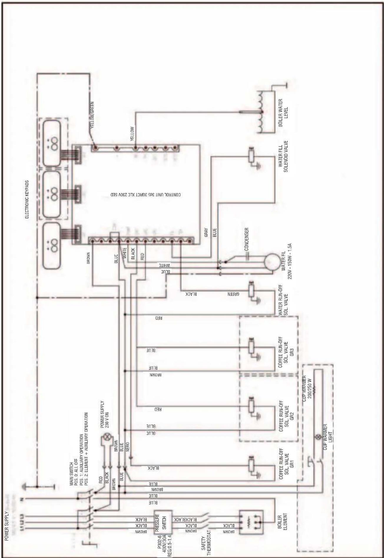
Electrical connection
Before connecting the power cable, follow the instructions below to install a safety switch and of the proper capacity:
Install ground cable, then phase cables. Uninstall phase cables first and then ground if needed.
Make sure the ground connection complies with existing standards and regulations.
To connect directly to the mains electricity supply, include a device to disconnect the appliance from the mains, with a contacts opening distance which allows complete disconnection in conditions of category III overtension, in compliance with the installation rules.
N.B. CHECK THAT THE DATA ON THE RATING PLATE CORRESPOND TO YOUR MAINS ELECTRICITY SUPPLY.
INSTALLING THE POWER SUPPLY CABLE
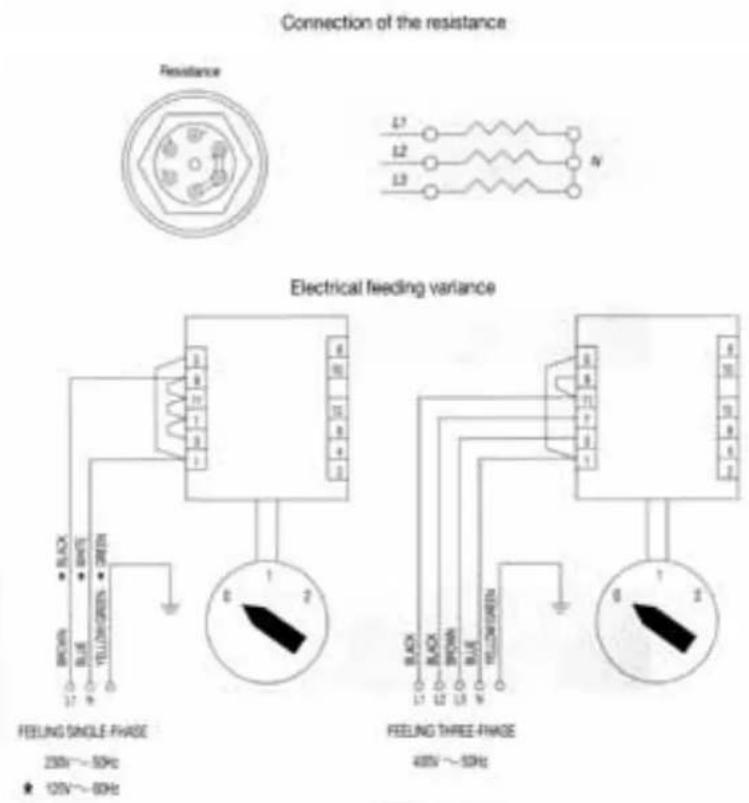
text_image
Connection of the resistance Resistance L1 L2 L3 N Electrical feeding variance FEELING SINGLE PHASE 250V~50Hz 125V~60Hz FEELING THREE PHASE 400V~50Hz
text_image
400 VOLTS THREE-PHASE + NEUTRAL BLACK PHASE (L1) BLACK PHASE L2 PHASE L3 BLUE NEUTRAL (R) YELLOWGREEN EARTH (W°) 200 VOLTS SINGLE-PHASE BROWN PHASE L1 BLUE NEUTRAL (R) YELLOWGREEN EARTH (W°) 100 VOLTS SINGLE-PHASE BLACK PHASE L1 WHITE PHASE L2 GREEN EARTH (W°)WATER CONNECTION
When installed, the boiler and heat exchangers are dry to avoid possible damage to the appliance caused by freezing.
1) The appliance must be supplied with cold water only.
2) If the mains pressure is higher than 0.6 Mpa (6 bars), you must install a pressure regulator with 0.6 Mpa (6 bars) maximum output pressure.
3) Connect the drain hose to the drip tray, avoiding excessively tight curves and sloping the hose appropriately to facilitate water flow.
4) Connect the 3/8" hose to the mains water supply, then to the water softener and the appliance.
Connect to the mains water supply in respect of national legislation.
N.B. The water softener is indispensable for correct operation of the appliance, to optimise coffee delivery in the cup and to extend the working life of components, as it purifies the water from limescale and residues that would otherwise shorten working life.
Failure to follow these instructions absolves the company from all liability.
Before connecting the pump intake tube, open the tap and run water through the water softener for about two minutes to eliminate possible.
IMPURITIES FILTER
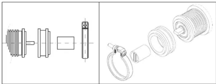
The impurities filter (code 10355150) is normally mounted on the hose connecting the purifier to the pump (fig. A) to prevent impurities in the water from damaging downstream components such as the pumping head, flow pumps, solenoid valves, etc.
The capsule filter (code 10355162) which blocks the impurities present in the water must be replaced about every three months.
The three month period is indicative only as the actual length of time is correlated to water consumption and the impurities present in the mains water supply.
To replace the pod filter: unscrew the impurities filter (code 10355150) and replace the pod filter.
Before inserting the new pod filter, make sure the inside of the body (10355152 and 10355154) is completely clean.
Any foreign matter must be removed to ensure correct filtration.
The impurities filter must be mounted according to the flow direction indicated by the arrow (fig. A) on the body
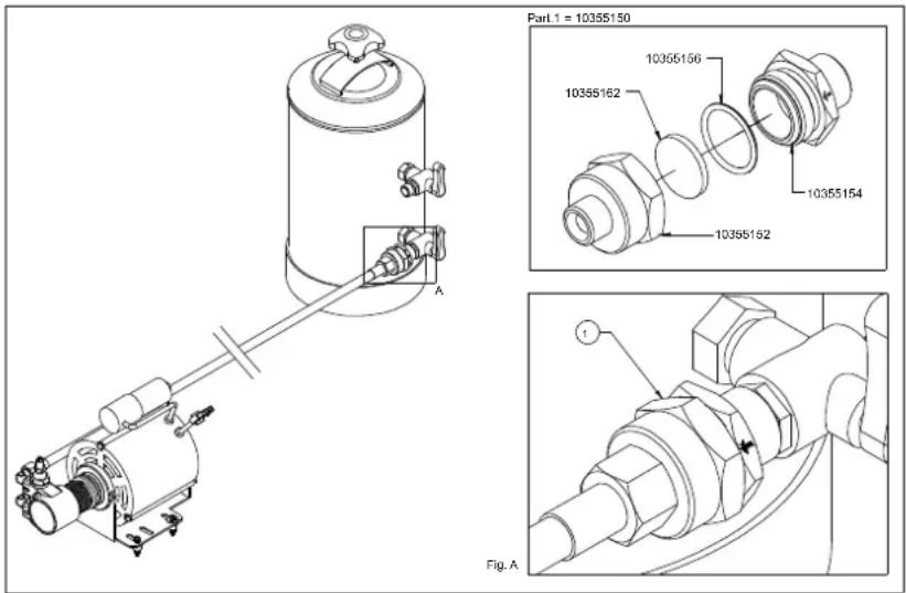
text_image
Part1 = 10355150 10355162 10355162 10355154 Fig. AUSE PRELIMINARY CHECK
Before using the appliance, check that:
- the plug is inserted properly into the mains power outlet;
- the water filling hose is correctly connected to the mains water outlet, check for leaks and that the water tap is open;
- the drain pipe is positioned in accordance with the preceding instructions.
With the steam tap (B) open, place the ON/OFF switch (D) in the 1 position and wait for the water in the boiler to reach the maximum level established by the electronic control unit. If the boiler does not fill within the set time-out (90 secs.), the pump stops and the keypad LEDs flash. In this case put the on/off switch (D) to position 0 and then to position 1 to finish filling the boiler.
Now put the on/off switch (D) to position 2 so that the heating elements are powered and therefore start to heat the water.

natural_image
Technical line drawing of a mechanical component with a central hub and mounting base, enclosed in a circular border (no text or symbols)Wait for steam to come out the steam nozzle (B), then close the tap and, using the Boiler pressure gauge, check that the pressure has reached and maintains a value of 0.8:1 bar. If it is not on this value, turn the adjusting screw on the pressure switch (+increase, - decrease, see figure below).
HOT WATER DELIVERY
Make sure the boiler pressure gauge shows a pressure of 0.5:1 bars.
Press the button (M6) to deliver hot water, then press again to stop delivery.
Take great care to avoid burns.
STEAM DELIVERY
All models have two steam nozzles on the sides of the work surface, with the exception of the one group machine which has just one. These steam nozzles are retractable and can be oriented by means of a ball joint. To deliver steam, turn the knobs (B) anticlockwise. Take great care to avoid burns.
COFFEE DELIVERY ZOE SAP MODEL
Insert the filter holder (E) into the group head (F) turning the filter holder counter-clockwise. Press the button (M5) and wait for the required quantity of coffee to be dispensed, press it again.
COFFEE DELIVERY ZOE SED MODEL
Insert the filter holder (E) in its seat (F) by turning it anticlockwise. Select the type of delivery required on the keypad (M):
M1=One short/standard coffee.
M2=One standard/long coffee.
M1=Two short/standard coffees.
M4=Two standard/long coffees.
M5=Electronic settings button or continuous manual delivery.
Before use, the operator must always check the indicator (L) to make sure that the level of water in the boiler is above the minimum level.
DISPENSER PROGRAMMING
a) To access this phase keep the button M5 on the first pushbutton panel on the left pressed for over 5 seconds. The indicator lights of the buttons M5 start to blink continuously. Select the caption corresponding to the amount required and press to dispense. The indicator light of button M5 and that of the selected caption remain lit. When the required amount has been dispensed, press the selected dispensing button again so that the control unit stores the data. Repeat the above procedure for all 4 dispensing buttons on the pushbutton panel. A dispensed quantity may also be set for the hot water button (M6) by repeating the above procedure. Upon completion of the procedure, the remaining groups will automatically use the stored quantity. The other groups may, however, be programmed independently by repeating the same procedure as above after having programmed the first group on the left.
b) There are 2 safety systems inside the control unit designed to protect the electronic system and the various parts of the appliance. If, upon pressing a dispensing button, the corresponding indicator light starts blinking, this indicates a malfunction in the electronic system or lack of water. For safety reasons, the dispensing of water stops after 4 minutes and in any case after 4 litres of water.
c) The ZOE electronics also offers the possibility of reproducing the pre-brewing effect by wetting the coffee for 0.6 seconds and then stopping the subsequent brewing from starting for 1.2 seconds. This option is only applicable for single shots of coffee.
TO ENABLE PRE-BREWING
With the appliance switched off, put the on/off switch (D) to position 1 and at the same time keep the button (M1) on the left-hand group pressed until the indicator light corresponding to the button (M5) remains lit; then release the button (M1). Now put the on/off switch (D) to position 0 and then to position 2 in order to store the operation.
TO DISABLE PRE-BREWING
With the appliance switched off, put the on/off switch (D) to position 1 and at the same time keep the button (M2) on the left-hand group pressed until the indicator light corresponding to the button (M5) remains lit; then release the button (M2). Now switch the appliance off and then on again using the on/off switch (D) in order to store the operation.
CLEANING
Spout assembly filter: after having dispensed the last cup of coffee, the filter and filter holder must be washed with water. If they are damaged, worn or clogged, they should be replaced.
Drip tray and grid: the drip tray and grid should be removed frequently and coffee residues cleaned away.
Water softener: the softener should be periodically regenerated according to the manufacturer's directions given in the instruction booklet.
External housing: the external housing and the steel parts should be cleaned with sponges and soft cloths to avoid scratching. Only use detergents that do not contain abrasive powders or solvents and do not use steel wool.
WARNINGS: when using the appliance it is recommended that the various instruments be kept under control, checking that they are in the previously indicated normal working conditions.
When the appliance has been left unused for a number of days, or every 2/3 months during normal use, to clean the internal circuits more efficiently, it is good practice to fill the boiler a number of times and deliver simple water and coffee to be thrown away.
APPLIANCE FAILURE
The user must check that this is not due to:
- power failure or blackout.
- lack of mains water supply or no water inside the boiler.
For any other causes, contact a qualified SANREMO After-Sales Service Centre.
BEFORE CARRYING OUT ANY WORK INSIDE THE APPLIANCE OR REMOVING ANY PART OF THE HOUSING, ALWAYS DISCONNECT FROM THE ELECTRICITY SUPPLY.
WARRANTY
Every purchased appliance (keep the receipt, invoice and delivery note) is covered by a statutory guarantee. This warranty envisages the replacement free of charge of parts that are shown to the service centre or manufacturer's satisfaction to be defective due to faulty materials or workmanship and providing that the appliance has not been misused or tampered with by unauthorised persons or persons using incorrect components or techniques.
Any defective part shall be returned to the manufacturer.
NOTE: never activate the pump without water. Excessive heat will damage the pump and no warranty replacement is granted in that case.
WARNINGS
The appliance must not be cleaned using a water jet.
Do not put the appliance in water.
The appliance must not be positioned near to any source of heat.
The appliance is unsuitable for outdoor installation.
Children must be supervised to make sure they do not play with the appliance.
The appliance must be installed in places where its use and maintenance is limited to qualified persons only.
Access to the service area is limited to persons with knowledge and practical experience of the appliance, particularly as regards safety and
hygiene aspects.
To ensure safe use the appliance must be in a level position.
If the power cable is damaged, have it replaced by a SANREMO After-Sales Service Centre, since a special tool is required for this purpose.
The appliance must be used in rooms with a temperature between 5°C and 35°C.
IN THE EVENT OF FAILURE OR MALFUNCTION, REQUEST SERVICE ONLY FROM QUALIFIED PERSONNEL AT THE AFTER-SALES SERVICE CENTRE.
The data and features indicated in this booklet are not binding on the manufacturer, which reserves the right to make changes to its models at any time.
The manufacturer shall not be under any liability for injury to persons or damage to property arising from failure to comply with the instructions given in this booklet.
INFORMATION FOR USERS
In accordance with article 13 of legislative decree no. 151 “Implementation of directives 2002/95/EC, 2002/96/EC and 2003/108/EC on restriction of the use of certain hazardous substances in electrical and electronic equipment and the disposal of waste”.
The appliance or packaging is marked with the symbol of a bin with a cross to indicate that at the end of its working life it must be disposed of separately from other waste.
Separate collection of this appliance at the end of its working life is organised and managed by the manufacturer.
The user wanting to dispose of this appliance should therefore contact the manufacturer and follow the separate waste collection system to dispose of the appliance at the end of its working life.
Appropriate separate collection and the subsequent recycling, treatment and ecological disposal of the disused appliance help avoid possible negative effects on the environment and health and encourage the re-use and/or recycling of the constituent materials.
The unlawful disposal of the product by the user is punishable by the administrative sanctions provided for by the legislation in force at the time.


text_image
R Q D ZOE S T Report to the service centre in case of cable damage as special equipment is required to make repairs. U V U DECONCENTRATOR / WATER NETWORLEGEND
D - MAIN SWITCH
0 - OFF
1 - PUMP AND AUTOMATISMS ON
2-PUMP, AUTOMATISMS AND ELECTRIC HEATING ON
Q - CUP WARMER ON/OFF SWITCH
LIT - ON
NOT LIT = OFF
R-CUP WARMER RESISTOR
S - 3-WAY BLOCK FEMALE
T - 3-WAY BLOCK MALE
U-WATER FILL DRIVE HOSE
V - EXTERNAL PUMP
Connect the external pump stably on its feet.
The pump must be kept away from sources of heat or water.
Warning – correct use of rotary pumps
1-Proper Alignment of Pump and Motor
On occasion the noise of a motor-pump assembly is caused by a poor alignment.
When the coupling between motor and pump is rigid, the pump rotor and the motor rotor may be out of axis. If this condition is maintained over time the most likely damage is seizure of the pump.
An efficient solution of this problem is the use of an elastic coupling between pump and motor. Fluid-o Tech supplies an optional kit code N. 10051020.
natural_image
Technical line drawings of mechanical components and assemblies (no text or symbols)2-Quality of Water.
Tight mechanical tolerances of components and materials used for rotary vane pumps require a very clean water, free from suspended particles. Sand, deposits on connecting pipes or the resins of the sweetener, when flowing through the pump, may scratch graphite parts causing problems of insufficient pressure and flow rate. If a closed loop hydraulic circuit is not available to guarantee a clean water and no sources of contamination Fluid-o-Tech recommend to install a 5-10 micron filter between the sweetener and the pump.
Recommended filter: food approved polipropilene wire cartridge. Keep the filter clean.: an upstream dirty filter will create cavitation and the pump will break shortly (see section 4).
3-Dry operation
Rotary vane pumps may operate in dry condition only for a very short time- few seconds!
Without a proper water cooling the temperature of the mechanical seal will increase very quickly with resulting breakage. The most likely impact is a remarkable leak visible from the four drain holes close to the motor clamp. For potential lack of feed from city water line Fluid-o-Tech recommend the installation of a minimum pressure safety switch upstream from the pump.
In case of feed from a tank install on the tank a minimum level switch.
4-Cavitation
Cavitation shows when feed flow rate does not match the pump design requirement: most frequent causes are dirty filters, small diameter pipes, more users on the same line.
Opening of the safety valve (generally installed upstream from pump and filter) must happen
before the pump start up. This will avoid cavitation. For the same reason closing of the safety valve must be delayed after the pump shut down.
The most noticeable effect is an increase of noise. If cavitation continues the impact is the same as of dry operation.
5-Back Feed of Hot Water
If a non return valve between the pump and the hot water vessel is defective the pump may come in contact with hot water(90-100°C). Dimensional variations of components will cause seizure of the pump.
6) Wrong connections
Pumps connectors are 3/8"NPT(conical) or 3/8" GAS(cylindrical).
Connectors with thread different from the recommended type are occasionally used. Sealing is made with a glue or with teflon tape. If the connector is forced it is possible to create beards; if excess sealing glue is used the extra quantity of glue may enter into the pump body.
In both cases it is likely to create a damage.
7) Pressure strokes
To avoid pressure strokes opening of solenoid valves installed downstream must happen before the start of the pump. For the same reason closing of the valve must be delayed after stopping of the pump. A pressure stroke may break graphite parts and damage mechanical seal causing blockage of the pump and leaks.
8) Handling
A crash on the floor may create deformations that will jeopardize the tight mechanical tolerances of the pump components. For the same reason be very careful when clamping the pump to mount or demount connectors.
9) Scale build up
Scale deposits will quickly show on inner components when using hard water, not sweetened with ion exchange resins.
Scale formation increases when the pressure relief valve is used as flow rate regulator: the rate of scale deposition increases with increasing of closed loop circulation. Scale deposits cause an increase of torque, occasional seizure of the pump or a reduction of operating pressure because the pressure relief valve cannot work properly.
To minimize this problem Fluid-o-Tech suggest to use pumps with flow rate matching the hydraulic circuit features.
In some circuits it is advisable to periodically remove scale with a chemical treatment.
MOD. ZOE 2GR SED / SAP

text_image
M6 M5 M4 M3 M2 M1 B T D C M1 M2 M3 M4 M5 M6 B F E P/N ZOEB - Steam tap knob
C – Water tap knob
D - On/off switch
0 - 0ff
1 - Pump and automatic devices on
2 - Pump, automatic devices and heating element on
E - Filter holder
F – Filter holder group head
I - Dispense - stop button

text_image
M6 M5 B T D C M5 M6 B F E P/NM1 - One strong coffee
M2 - One weak coffee
M3 - Two strong coffees
M4 - Two weak coffees
M5 - Continual dispensing and programming key
M6 - Hot water
N - Pump pressure gauge
P – Boiler pressure gauge
T – Cup warmer switch (Optional)
text_image
Technical schematic diagram of a fluid or pneumatic system with numbered components and piping connections
Variantos
LEGEND
1 Water supply
2 Softener
3 Water in tap
4 Water out tap
5 Pump and electric motor
6 Pressure gauge (boiler pressure)
7 Check valve
8 Filling block with filter
9 Solenoid valve for automatic fill
10 Expansion valve
11 Volumetric meter
12 Fill tap
13 Boiler drain tap
14 Boiler
15 Heat exchanger
16 Boiler resistor
17 Safety valve
18 Vacuum breaker valve
19 Pressure gauge (boiler pressure)
20 Steam tap
21 Hot water run-off solenoid valve
23 Level sensor 1-2Gr
26 Pressure switch
34 Spout group
35 Spout group solenoid valve
36 Filter holder
38 Filter
text_image
Exploded view diagram of a device with numbered components and internal parts, likely for assembly or manufacturing purposes.Exploded view MOD. ZOE update 03/12
LEGEND EXPLODED DIAGRAM ZOE SAP - SED UPDATE 03-12
| POS. COD. DESCRIPTION | |
| 1A 10017302 FRAME ZOE 2GR MATT BLACK | |
| 1B 10017304 FRAME ZOE 2GR WHITE | |
| 2A 10017372 PANEL RH ZOE GLOSSY BLACK | |
| 2B 10017374 PANEL RH ZOE RED | |
| 2C 10017376 PANEL RH ZOE PURPLE | |
| 2D 10017378 PANEL RH ZOE MAIT BLACK | |
| 2E 10017380 PANEL RH ZOE PEARL WHITE | |
| 2F 10017382 PANEL RH ZOE YELLOW | |
| 2G 10017384 PANEL RH ZOE GREEN | |
| 3A 10017392 PANEL RH ZOE GLOSSY BLACK | |
| 3B 10017394 PANEL RH ZOE RED | |
| 3C 10017396 PANEL RH ZOE PURPLE | |
| 3D 10017398 PANEL RH ZOE MATT BLACK | |
| 3E 10017400 PANEL RH ZOE PEARL WHITE | |
| 3F 10017402 PANEL RH ZOE YELLOW | |
| 3G 10017404 PANEL RH ZOE GREEN | |
| 4 10017324 TOP TANK ZOE 2GR ST. | |
| 5A 10017332 REAR PANEL ZOE 2GR GLOSSY BLACK | |
| 5B 10017334 REAR PANEL ZOE 2GR RED | |
| 5C 10017336 REAR PANEL ZOE 2GR PURPLE | |
| 5D 10017338 REAR PANEL ZOE 2GR MATT BLACK | |
| 5E 10017340 REAR PANEL ZOE 2GR PEARL WHITE | |
| 5F 10017342 REAR PANEL ZOE 2GR YELLOW | |
| 5G 10017344 REAR PANEL ZOE 2GR GREEN | |
| 6 10352430 CUP RETAINER ZOE 2GR TRANSPARENT | |
| 8 10017326 TOP GRILLE ZOE 2GR | |
| 10A 10017352 PROTECT. GROUPS ZOE 2 GLOSSY BLACK | |
| 10B 10017354 PROTECT. GROUPS ZOE 2 RED | |
| 10C 10017356 PROTECT. GROUPS ZOE 2 PURPLE | |
| 10D 10017358 PROTECT. GROUPS ZOE 2 MATT BLACK | |
| 10E 10017360 PROTECT. GROUPS ZOE 2 PEARL WHITE | |
| 10F 10017362 PROTECT. GROUPS ZOE 2 YELLOW | |
| 10G 10017364 PROTECT. GROUPS ZOE 2 GREEN | |
| 11 10017328A DRAIN GRILLE ZOE 2GR FILINOX | |
| 12 10017322 DRIP TRAY ZOE 2GR | |
| 13A 10017472 BOTTOM FRONT PANEL 2GR MATT BLACK | |
| 13B 10017474 BOTTOM FRONT PANEL ZOE 2GR WHITE | |
| 14 10017320 FRONT PROTECTION ZOE 2GR | |
| 15 10352065 TELESCOPIC FOOT D50X55 INOX | |
| 16 10012144 FLOW REGULATOR FOR DRIP TRAY | |
| 17 10022441 UNIVERSAL DRIP TRAY | |
| 18 10806099 HOSE CLIP INOX | |
| 19A 10455050 RESISTOR 1950W 230V 1GR | |
| 19B 10455051 RESISTOR 1950W 120V 1GR | |
| 19C 10455052 RESISTOR 2700W 230V 2GR | |
| 19D 10455053 RESISTOR 2700W 120V 2GR | |
| 19E 10455054 RESISTOR 5100W 230V 3GR | |
| 19F 10455060 RESISTOR 2400W 230V 1GR | |
| 19G 10455065 RESISTOR 2400W 120V 1GR | |
| 19H 10455080 RESISTOR 4500W 230V 2GR | |
| 20 10502020 WASHER D56X41X2mm PTFE | |
| 21 10002670 BOILER COPPER 2GR 10 LITRES D. 190 | |
| 22A 10252079A EL. MOTOR 150W 120V 1-2GR | |
| 22B 10252080A EL. MOTOR 150W 230V 1-2GR | |
| 22C 10252086 EL. MOTOR 165W 230V 2-3GR | |
| 22D 10252094 EL. MOTOR 150W 230V CB 2-3GR | |
| 22E 10252098 EL. MOTOR 130W 230V CB VENTILATED 1-2GR | |
| 23 10255022 VIBRATION DAMPER PUFFER | |
| 24A 10252070B ROTARY PUMP 150L/H 1-2GR | |
| 24B 10252072B ROTARY PUMP 204L/H 2-3GR | |
| 25 10602010A PRESSURE SWITCH | |
| 26A 10112012 CONTROL UNIT XLC SED 120V |
| 26B 10112072E CONTROL UNIT XLC SED 230V |
| 26C 10112083C CONTROL UNIT ON-OFF 1-2-3GR XLC |
| 27 10303093A 2-WAY SOLENOID VALVE BAS. 32X32 230V |
| 28 10112134 VOLUMETRIC METER 1/8" |
| 29A 10122050 JUMPER SWITCHER SINGLE PHASE |
| 29B 10122060 JUMPER SWITCHER THREE PHASE |
| 30 10052028A SPOUT ASSY. RING WITH FILTER DISK AND GASKET E61 |
| 31A 10302066 3-WAY SOLENOID VALVE BAS. 32X32 230V |
| 31B 10305555 3-WAY SOLENOID VALVE BAS. 32X32 120V |
| 32A 10553021 INDICATOR LIGHT ORANGE D6 230V WIRED |
| 32B 10553024 INDICATOR LIGHT ORANGE D6 120V WIRED |
| 33A 10102560 WIRING ZOE 2GR SED WITH RING ASSY. |
| 33B 10102570 WIRING ZOE 2GR SAP WITH RING ASSY. |
| 34 10552018 PRESSURE GAUGE |
| 35 10852210 L-UNION 2020 1/8" F/M |
| 36 10859029 REDUCER UNION 1/8"M 3/8"M CHROMED MI |
| 37 10402056A OR 2062 VITON |
| 38 10402043 SWIVEL JOINT SPRING |
| 39 10402054 SWIVEL JOINT CAP |
| 40 10402082 LANCE SWIVEL JOINT OR D10 |
| 41 10402282 STEAM LANCE NUT MLX |
| 42 10402288 LANCE BALL JOINT MLX |
| 43 10402274 STEAM TUBE POLISH. INOX STEAM LANCE RM |
| 44 10753052 ANTI-BURN JOINT |
| 45A 10402276 NOZZLE INOX 2 SIDE HOLES |
| 45B 10402279 NOZZLE INOX 4 HOLES |
| 46 10402081 LANCE TUBE OR MLX |
| 47 10402266 BALL JOINT INOX WATER 1/8" M |
| 48 10505018 OR D.7.2X1.9 EPDM OR6 BOILER OUTLET |
| 49 10402140 BOILER OUTLET |
| 50 10402143 BOILER WATER OUTLET SHORT COMPL. |
| 51 10401982 WATER TAP COMPL. ZOE 230V |
| 52 10402120A TAP BODY |
| 53 10505561 TAP BUSH COPPER |
| 54 10505121 TAP ROD OR NBR |
| 55 10402015 TAP SHAFT BUSH |
| 56 10402014 TAP SHAFT SPRING |
| 57 10402061 CENTRAL TAP SHAFT |
| 58 10505558 TAP SHAFT GASKET |
| 59 10803547 WASHER D20 FLAT ZN |
| 60 10806312 TOOTHED WASHER D21 ZN |
| 61 10092164A STEAM KNOB ROMA |
| 62 10806370B TAP SPLIT PIN |
| 63 10092162A STEAM KNOB CAP ROMA |
| 64 10402040 TAP WASHER BRASS |
| 65 10402028 HALF NUT 1/2" CHR. RAISED |
| 66A 10303060A 2-WAY SOLENOID VALVE 1/8" 120V UL-CSA |
| 66B 10303086 2-WAY SOLENOID VALVE 1/8"230V |
| 67 10402484A STEAM LANCE COMPL. RM-VM-ZOE D.10 |
| 69 10402310C FILTER HOLDER ASSY. 1 CUP 1,3 |
| 70 10402312B FILTER HOLDER ASSY. 2 CUP 1,3 |
| 71 10052085 SPOUT 2-WAY, OPEN |
| 72 10091150 FILTER HOLDER HANDLE VR-RM |
| 73 10052034 FILTER HOLDER BODY |
| 74 10052055 FILTER RETAINER SPRING 1,3 |
| 75A 10052100 FILTER 1 CUP |
| 75B 10052101 FILTER 1 CUP 6GR POD MOD. |
| 76 10052110 FILTER 2 CUP |
| 77 10052220 BLIND FILTER |
| 78 10052075 SPOUT 1-WAY, OPEN |
| 79A 10052206A RING ASSY. CA GDE61 230V |
| 79B 10052208A RING ASSY. CA GDE61 120V |
| 80 10255028A ELBOW UNION ROT. F1/8 |
| 81 10852030A ELBOW UNION 1020 6-1/8" |
| 82 10091154 FILTER HOLDER HANDLE RING VR-RM |
| 83 10852080A STRAIGHT UNION 1050 6-1/8"M |
| 84 10091152 FILTER HOLDER HANDLE CAP VR-RM |
| 85 10355172 ROUND MESH FILTER |
| 86 10056058A FILLING BLOCK BODY LIGHT |
| 87 10655557 EXPANSION VALVE |
| 90 10255058 ELBOW UNION ROTATING 1/8M |
| 92 10056110 FILLING BLOCK ASSY. 230V LIGHT |
| 93 10105022 CABLE GLAND PA268 |
| 94 10105024 SCREW TC+ 3.5X25 ZN CABLE GLAND |
| 95 10805071 SCREW TCEI M4X10 A2 |
| 96 10502070A OR 3187 EPDM FDA |
| 97 10052248 MAZZOCCO RING ASSY. FOR GASKET AND FILTER DISK E61 |
| 98 10052141 DIFFUSER GR. E61 |
| 99 10052120 MESH BOILER OUTLET GR. E61 |
| 100 10502110 UNDER CUP GASKET GR. E61 |
| 101 10052142 CLOSURE CAP GIGLEUR GR. RING |
| 102 10052143 TOP CAP GASKET GR. RING |
| 103 10052135 GIGLEUR HOLE GR. D.0.8 |
| 104 10852033 EXTENSION NI CA GR. RING |
| 105 10052136 FILTER ASSY. E-61/RING |
| 106 10805078 SCREW TCEI M6X8 A2 |
| 107 10111015 THERMOSTAT WITH MAN. RESET |
| 108 10805872 SCREW TC+ M4X6 ZN |
| 110 10805116 SCREW TC+ M3X10 ZN TRUC. BLACK SWITCHER KNOB |
| 111 10122015 SWITCHER KNOB |
| 112 10105190 2-WAY BLOCK F. |
| 114 10402059 DRAIN TAP WITH KNOB |
| 115 10852050A STRAIGHT UNION 1050 8-1/8"M |
| 116 10022476 DRIP TRAY COVER |
| 117 10402060 BOILER DRAIN TAP KNOB |
| 118 10853058 STRAIGHT HOSE CONNECTION 1510 6-1/8"M |
| 119 10905010 SILICONE HOSE TRANSP. |
| 120A 10102190 POWER CABLE 3X2.5 MT3 N5 SINGLE PHASE |
| 120B 10102191 POWER CABLE 5X2.5 MT3 N4 THREE PHASE |
| 120C 10102193 POWER CABLE 3X4 MT3 N7 |
| 120D 10102196 POWER CABLE 3x12AWG SJOOW 3MT |
| 120E 10102197 POWER CABLE 3x14AWG SJOOW |
| 121 10803519 TOOTHED WASHER D4.2 ZN |
| 122 10805512 NUT 4MA MEDIUM ZN |
| 123 10852484 DRIVE HOSE L=2000 |
| 124 10852470 DRIVE HOSE L=450 |
| 125 10852290A STRAIGHT UNION 1050 10-3/8"M |
| 126 10852293A STRAIGHT UNION 1050 8-3/8"M |
| 127A 10112268 KEYPAD TO 6 KEYS SED |
| 127B 10112274 KEYPAD TO 2 KEYS SAP |
| 128A 10112078 CABLE PIN TO PIN, 600mm |
| 128B 10112079 CABLE PIN TO PIN, 800mm |
| 129 10556041A CUP WARMER SWITCH RED |
| 130 10852460 SPIRAL DRAIN HOSE L.2 MT |
| 131A 10017412 KEYPAD SUPPORT SED ZOE BLACK |
| 131B 10017414 KEYPAD SUPPORT SED ZOE WHITE |
| 131C 10017432 KEYPAD SUPPORT SAP ZOE BLACK |
| 131D 10017434 KEYPAD SUPPORT SAP ZOE WHITE |
| 132 10022552 SAFETY VALVE TANK COPPER |
| 133 10105030 CABLE GLAND IN BLACK RUBBER |
| 134 10852580A STRAIGHT UNION 1050 6-1/4"M |
| 135 10852821 UNION 2070 T M/F/F 1/4" |
| 136 10852250A ELBOW UNION 1020 6-1/4"M |
| 137 10112042 LEVEL SENSOR 140mm CA 2GR |
| 138 10652040A BOILER AIR VENT VALVE |
| 139 10852180 WASHER 1/4" COPPER |
| 140 10853053A INTAKE TUBE 1/4"M |
| 141 10106060 JUMPER RESISTOR COPPER |
| 142 10652012 SAFETY VALVE |
| 143A 10052174 GIGLEUR HOLE D2.5 |
| 143B 10052176 GIGLEUR HOLE D3 | |
| 143C 10052178 GIGLEUR HOLE D3.5 | |
| 143D 10052179 GIGLEUR HOLE D2 | |
| 144 1006324 WASHER 3/8" COPPER | |
| 145 10052540 CAP 261 1/4"M | |
| 146 10052060A ELBOW UNION 1020 8-1/4"M | |
| 150 10053298 BOTT. HEAT EXCHANGER UNION 1/4"-3/8"-3/8" | |
| 151 10052240A UNION 1170 6-1/4" | |
| 152 10042040 | INJECTOR PTFE D.8 |
| 153 10052780 | T-UNION 2090 1/8 M/F/M |
| 155 10052028A T-UNION 1010 6-6-1/8"M | |
| 156 10003344 SCREW TSP+ M4X10 A2 | |
| 157 10005074 SCREW TE M4X8 ZN | |
| 158 10005027A SCREW TBL+ M4x10 A2 | |
| 159 10009011 FLANGED NUT 4MA | |
| 160 10005022 SCREW TBL-M4X20 A2 | |
| 161 100405540 BALL PRESSER | |
| 162 10017490 ANTIFRCTION PLATE | |
| 163 10006050 NUT M4 X RESISTOR | |
| 164A 100952051B | RATING PLATE AL. SAN REMO 230V |
| 164B 100952052B RATING PLATE AL. SAN REMO 400V | |
| 164C 100952053A RATING PLATE AL. SAN REMO 120V | |
| 165 10005950 SHEAR RIVET D3x6 | |
| 166 100955060C LABEL SAN REMO 117.5X19.4X2M | |
| 167 100955013 TRIANGULAR HOT SURFACE LABEL | |
| 168 100955025A TRIANGULAR EARTH LABEL | |
| 169 100955015 TRIANGULAR VOLTAGE LABEL | |
| 170 10005038 SCREW TSP+ M3X6 A2 | |
| 171 10009012 FLANGED NUT 6MA | |
| 172 10003536 TOOTHED WASHER D6.2 ZN | |
| 173 10005075 SCREW TE M5X8 ZN | |
| 174 10003520 TOOTHED WASHER D5.3 ZN | |
| 175A 10252038 MOTOR CONDENSER 150W | |
| 175B 10252040 CONDENSER 10 MF 450VL MOTOR 165W | |
| 176 10105243B TRANSPARENT SWITCH CAP | |
| 177 10003050 TUBE TOP HEAT EXCHANGER CA 2 DLX | |
| 178 10003052 TUBE BOTT. HEAT EXCHANGER CA 2 DLX | |
| 179 10003224 STEAM HOSE RH ZOE 2 | |
| 180 10003222 STEAM HOSE LH ZOE 2 | |
| 181 10003226 HOT WATER RUN-OFF HOSE ZOE 2 | |
| 182 10003220 PRESS. SW. TUBE ZOE 2 | |
| 183 10003160 BOILER FILL HOSE CA DLX 2 | |
| 184 10003166 FILL HOSE 1°GR CA 2 DLX SED CB | |
| 185 10003228 BOILER DRAIN HOSE ZOE 2 | |
| 186 10002060 JUMPER TUBE 1°-2°VOLUM. CA 2 SED | |
| 187A 10003162 | FILL HOSE VOLUM. CA1-2 DLX SED CB |
| 187B 10003170 FILL HOSE GR CA DLX-MI 2 SAP CB | |
| 188 10003168 FILL HOSE 2°GR CA 2 DLX SED CB | |
| 189 10003172 JUMPER TUBE 1°-2°GR CA DLX SAP CB | |
| 190 10009024 WASHER D.4.3 COPPER | |
| 191 10002028 BOILER PRESS. SW. CAPILLARY TUBE PI | |
| 192 10002021 PUMP PRESS. SW. CAPILLARY TUBE VE | |
| 193 10005084 SCREW TC+ M4X10 ZN | |
| 194 10052064 DRIP TRAY CAP | |
| 195 10053296 TOP HEAT EXCHANGER UNION 3/8"-3/8" | |
| 196 10022554 SAFETY VALVE TANK COVER COPPER | |
| 197 10022556 SCREW TC+ 2.9X4.5 ZN TANK COPPER | |
| 198 100503018 PISTON ASSY. GASKET SILICONE | |
| 199 100905024 SILICONE HOSE D12X18 | |
| 200 10352058 EXTERNAL PUMP FOOT | |
| 201A 10252087 EL. MOTOR 300W 230V P.E 1-2GR | |
| 201B 10252089 EL. MOTOR 187W 230V P.E. 2-3GR | |
| 201C 10252096 EL. MOTOR 150W 230V P.E. 1-2-3GR CB | |
| 202 10102595A CONNECT. WIRING MACHINE/EXT. PUMP | |
| 203 10102620A CONNECT. WIRING MOTOR E.P. 2GR | |
204 10355150 FILTER PUMP CONNECTION 3/8"
205 10112105 SERIAL OUTPUT CABLE RS232
206 10102566 CUP WARMER WIRING ZOE 2GR
207 10455122 CUP WARMER RESISTOR 2GR D6.4
VORAUSSETZUNG
natural_image
Technical line drawing of a 3D mechanical device with internal components and XYZ coordinate axes (no text or symbols)natural_image
Technical line drawing of a mechanical component with a central pin and mounting bracket (no text or symbols)HEISSWASSERAUSGABE
text_image
Technical diagram showing mechanical assembly and component detail with labeled code Cod. 100510202) WASSERQUALITÄT
text_image
Technical schematic diagram of a fluid or pneumatic system with numbered components and piping connectionsVarianten
LEGENDE
text_image
Exploded view diagram of a device with numbered components and internal parts, likely for assembly or manufacturing purposes.natural_image
Technical line drawing of a laboratory apparatus with 3D coordinate axes (X, Y, Z) shown in the same view, no text or symbols present.CARACTÉRISTIQUES TECHNIQUES
| GROUPES | 2 | |
| LARGEUR (X) mm 720 | ||
| PROFONDEUR (Y) mm 528 | ||
| HAUTEUR (Z) mm 537 | ||
| CAPACITÉ litres 10 | ||
| POIDS NET Kg 62,7 | ||
| POIDS BRUT Kg 65 | ||
| TENSION D'ALIMENTATION V | 120220-240 1N~380-415 3N~ | |
| PUISSANCE ABSORBÉE PAR LA RÉSISTANCE (230 V) | kW | 2,95/4,9 |
| PUISSANCE ABSORBÉE PAR LA RÉSISTANCE CHAUFFE-TASSES (optional) | kW | 0,2 |
| PUISSANCE ABSORBÉE PAR L'ÉLECTROPOMPE | kW | 0,2 |
| PUISSANCE ABSORBÉE PAR L'ÉLECTROPOMPE EXTERNE | kW | 0,2 |
| PUISSANCE ABSORBÉE PAR LES ÉLECTROVANNES | kW | 0,0225 |
| PUISSANCE ABSORBÉE PAR LE RÉGULATEUR AUTOM. DE NIVEAU | kW | 0,01 |
| PRESSION DE SERVICE CHAUDIÈRE | (0,8-1 bars) MPa | 0,08:0,1 |
| PRESSION RÉSEAU D'EAU (MAX) | (6 bars) MPa | 0,6 |
| PRESSION DE DISTRIBUTION CAFÉ | (8-9 bars) MPa | 0,8/0,9 |
natural_image
Technical line drawing of a mechanical component with a circular outline (no text or symbols)SORTIE EAU CHAUDE
text_image
Technical diagram showing mechanical assembly and component details with labeled code Cod. 100510202) QUALITÉ DE L'EAU
text_image
Technical schematic diagram of a fluid or pneumatic system with numbered components and piping connections
Variantes
LÉGENDE
text_image
Exploded view diagram of a mechanical assembly with numbered parts and exploded viewsnatural_image
Technical line drawing of a 3D mechanical device with internal components and coordinate axes (X, Y, Z) shown in the same view.CARACTERÍSTICAS TÉCNICAS
natural_image
Technical line drawing of a mechanical component with a vertical rod and circular base, no text or symbols presenttext_image
Technical diagram showing mechanical assembly and component details with labeled code Cod. 100510202) CALIDAD DEL AGUA
D - Interruptor general
0 - Apagado
text_image
Technical schematic diagram of a fluid or pneumatic system with numbered components and piping connections--- Variantes