Aurelia S - Coffee machine NUOVA SIMONELLI - Free user manual and instructions
Find the device manual for free Aurelia S NUOVA SIMONELLI in PDF.

User questions about Aurelia S NUOVA SIMONELLI
0 question about this device. Answer the ones you know or ask your own.
Ask a new question about this device
Download the instructions for your Coffee machine in PDF format for free! Find your manual Aurelia S - NUOVA SIMONELLI and take your electronic device back in hand. On this page are published all the documents necessary for the use of your device. Aurelia S by NUOVA SIMONELLI.
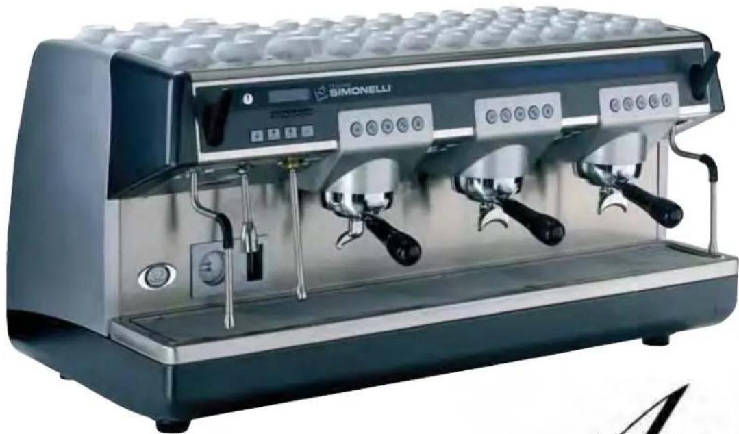
USER MANUAL Aurelia S NUOVA SIMONELLI
espresso coffee machines
natural_image
Exterior view of a modern BIMONELLI coffee machine (no visible text or symbols on the device body)Aurelia®
MADE IN ITALY
LIBRETTO ISTRUZIONI
USER HANDBOOK
EC DECLARATION OF CONFORMITY


nuova simonelli
espresso coffee machines
Via M. D'Antegiano, 6 - 62031 Belforte del Chienti (MC)
declare under our responsibility that the product:
MACCHINE PER CAFFE' ESPRESSO
ESPRESSO COFFEE MACHINES
MODELS: Aurelia - versions Vip Plus, V, Esse.
to which this declaration relates, following the provisions of the Directives:
EN 60335-2-75:2004 + A1:2005 + A11:2006
in combination with
EN 60335-1:2002 + A1:2004 + A11:2004 + A12:2006 + A2:2006
EN 50366:2003 + A1:2006
following the provisions of the Directives
2006 / 95 / CE Low Voltage
2004 / 108 / CE (EMC)
data: Novembre 2008
November 2008
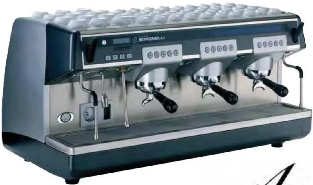
natural_image
Modern espresso machine with three dual leavers and control buttons (no visible text or symbols)
text_image
Aurelia® MADE IN ITALYCARATTERISTICHE TECNICHE
text_image
Technical diagram of a coffee machine with labeled components and directional arrows indicating flow or movement.
text_image
E D C| 2 Gruppi 3 Gruppi 4 Gruppi | ||||||
| PESO NETTO | 74 kg | 136 lb | 88kg | 194 lb | 104 kg | 229 lb |
| PESO LORDO | 80kg | 176 lb | 98 kg | 216 lb | 120 kg | 264 lb |
| POT. TERMICA | 4500 W | 4500 W | 5000 W | 5000 W | 5000 W | 5000 W |
| DIMENSIONI 780 mm 30° | A | 14" | A 1010mm 39 | 516" | A 1240 mm 48 | 516" |
| B 635 mm | B 25" | B 865 mm | B 34" | B 1095 mm | B 43116" | |
| C 540 mm | C 2118" | C 540 mm | C 2118" | C 540 mm | C 2118" | |
| D 315 mm 12 | D 316" 315 mm | D 12 | D 316" 315 mm | D 12 | D 316" | |
| E 510 mm | E 20" | E 510 mm | E 20" | E 510 mm | E 20" | |
| F 135 mm | F 518" | F 135 mm | F 518" | F 135 mm | F 518" | |
| G 180 mm 7 | G 116" 180 mm | G | G 116" 180 mm | G | G 116" | |

text_image
Aurelia® MADE IN ITALYINDICE
CARATTERISTICHE TECNICHE .....2
- DESCRIZIONE ....5
1.1 LISTA ACCESSORI 6
-
PRESCRIZIONI DI SICUREZZA .....7
-
TRASPORTO E MOVIMENTAZIONE ....10
3.1 IDENTIFICAZIONE MACCHINA 10
3.2 TRASPORTO 10
6.1 ACCENZONE DELLA MACCHINA 14
6.1.1 AURELIA VIP PLUS 14
6.1.2 AURELIA V/ESSE 15
6.1.3 AURELIA VIP-V/ESSE CON GIORNALE ELETTRONICO (OPTIONAL) .....15
natural_image
Simple line drawing of a mountainous landscape with a cross symbol and a small object, no text or symbols present.
natural_image
Simple white cross symbol on dark gray circular background, no text or numbers presentFig. 4

natural_image
Illustration of a hand operating a control panel with buttons and dials (no text or symbols visible)
natural_image
Simple line drawing of a landscape with mountains, trees, and a marked cross symbol (no text or labels)
natural_image
Illustration of a hand using a washing machine to adjust a component, with a black X symbol indicating no text or symbols.
natural_image
Diagram showing a mechanical device being inserted into a container and then placed on a surface, with no visible text or symbols.natural_image
Hand operating a car with directional arrows indicating cycle (no text or symbols)natural_image
Close-up of a car engine bay with visible components and a circular arrow indicating rotation (no text or symbols)natural_image
Close-up of a mechanical device with multiple metal components and a labeled component 'A' (no readable text or symbols beyond label)natural_image
Mechanical assembly diagram showing internal components with directional arrows indicating motion (no text or symbols)natural_image
Two metallic key-shaped tools with circular holes and a separate ring, labeled Fig. 20 (no text or symbols on the keys or ring)6.1 ACCENSIONE DELLA MACCHINA
6.1.1 AURELIA VIP PLUS
natural_image
Simple line drawing of a device with four circular buttons and a curved base, labeled Fig. 24 (no text or symbols on the diagram itself)natural_image
Illustration of a hand using a magnifying glass to press a small object, labeled Fig. 25 (no text or symbols on the diagram itself)natural_image
Hand operating a device with a knob and control panel (no visible text or symbols)natural_image
Illustration of a hand using a coffee machine to pour milk from a glass cup (no text or symbols visible)natural_image
Three identical illustrations of a washing machine with circular gauges and a person standing on the floor, labeled Fig. 29 (no text or symbols on the devices themselves)| 40 cc | 60 cc | 50 cc 85 | cc 9 sec. | 0 sec. |
natural_image
Close-up of a stainless steel coffee maker with control buttons (no visible text or symbols)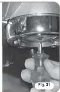
natural_image
Close-up of a hand holding a mechanical component, possibly a valve or pump, with no visible text or symbols.natural_image
Diagram of a cylindrical device with internal components and labeled point D, no text or symbols present- MESSAGGI FUNZIONI MACCHINA Aurelia Plus
By purchasing the you have made an excellent choice.
The purchase of a professional espresso coffee-maker involves various elements of selection: the name of the manufacturing firm, the machine's specific functions, its technical reliability, the option of immediate and suitable servicing, its price. You certainly evaluated all these factors and then made your choice: the Auceliv model.
We think you have made the best choice and after every coffee and cappuccino you will be able to assess this.
You will see how practical, convenient and efficient working with _phoebe is.
If this is the first time you have bought a Nuova Simonelli coffee machine, welcome to high quality coffee-making; if you are already a customer of ours, we feel flattered by the trust you have shown us.
Thanks of the preference.
With best wishes,
natural_image
Modern espresso machine with three dual leavers and control buttons (no visible text or symbols)
text_image
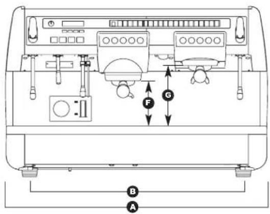
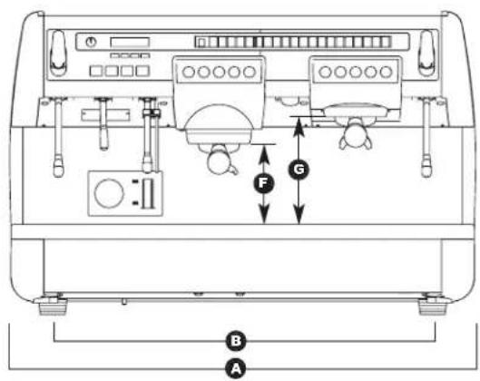
Aurelia® MADE IN ITALYTECHNICAL CHARACTERISTICS
text_image
Technical diagram of a coffee machine with labeled parts A, B, and F indicating seating or positioning.
text_image
E D C| 2 Groups 3 Groups 4 Groups | ||||||
| NET WEIGHT | 74 kg | 136 lb | 88kg | 194 lb | 104 kg | 229 lb |
| GROS WEIGHT | 80kg | 176 lb | 98 kg | 216 lb | 120 kg | 264 lb |
| POWER | 4500 W | 4500 W | 5000 W | 5000 W | 5000 W | 5000 W |
| DIMENSIONS 780 mm | A | A 14" 1010 mm | A 39 | A 516" | A 1240 mm | A 48516" |
| B 635 mm | B 25" | B 865 mm | B 34" | B 1095 mm | B 43116" | |
| C 540 mm 21 | C 18" | C 540 mm | C 2118" | C 540 mm | C 2118" | |
| D 315 mm | D 12316" 315 mm | D2 | D 316" | D 315 mm 12 | D 316" | |
| E 510 mm | E 20" | E 510 mm | E 20" | E 510 mm | E 20" | |
| F 135 mm | F 518" | F 135 mm | F 518" 135 mm | F 5 | F 18" | |
| G 180 mm | G 7116" | G 180 mm | G 7116" | G 180 mm | G 7116" | |

text_image
Aurelia® MADE IN ITALYINDEX
TECHNICAL CHARACTERISTICS .....34
- DESCRIPTION .....37
1.1 ACCESSORIES LIST ....38
-
SAFETY PRESCRIPTION .....39
-
TRANSPORT AND HANDLING .....44
3.1 MACHINE IDENTIFICATION 44
3.2 TRANSPORT 44
3.3 HANDLING 44
- INSTALLATION AND PRELIMINARY
OPERATIONS 44
- ADJUSTMENTS TO BE MADE BY A
QUALIFIED TECHNICIAN ONLY .....46
5.1 FILLING BOILER MANUALLY 46
5.2 PRESSOSTAT/PUMP ADJUSTMENT 46
5.3 HOT WATER ECONOMISER ADJUSTMENT .....47
5.4 CLOCK BATTERY REPLACEMENT (ONLY FOR THE VIP PLUS VERSION) .....47
5.5 PUSH-BUTTON PANEL REPLACEMENT .....47
5.6 ELECTRONIC DISPLAYS 47
- USE 48
6.1 TURNING THE MACHINE ON 48
6.1.1 AURELIA VIP PLUS 48
6.1.2 AURELIA V/ESSE 49
6.1.3 AURELIA VIP-V/ESSE WITH ELECTRONIC DISPLAYS (OPTIONAL) 50
6.2 SELECTION CONFIGURATION ....50
6.3 MAKING COFFEE 50
6.4 USING STEAM 50
6.5 MAKING CAPPUCCINO 51
6.6 HOT WATER SELECTION .....51
6.7 TIMED STEAM NOZZLE 51
- PROGRAMMING .....52
7.1 KEY 52
7.2 PROGRAMMING AURELIA VIP PLUS ....52
7.3 PROGRAMMING AURELIA V 58
7.4 PROGRAMMING AURELIA ESSE .....61
- CLEANING AND MAINTENANCE .....62
8.1 SWITCHING OFF THE MACHINE....62
8.2 CLEANING THE OUTSIDE OF THE MACHINE .....62
8.3 CLEANING STAINLESS COFFEE-HOLDERS .....62
8.4 CLEANING THE UNIT WITH THE AID OF THE
BLIND FILTER 62
8.5 CLEANING FILTERS AND FILTER-HOLDERS .....62
8.6 RESIN AND SOFTENER REGENERATION .....63
- AURELIA PLUS MACHINE FUNCTION
MESSAGES 64
- AURELIA V MACHINE FUNCTION
MESSAGES 66
- AURELIA S MACHINE FUNCTION
MESSAGES....67
ELECTRIC SYSTEM AURELIA S .....69
ELECTRIC SYSTEM AURELIA PLUS
Rel 3.xx 70
ELECTRIC SYSTEM AURELIA PLUS
Rel 1.xx ....71
ELECTRIC SYSTEM AURELIA V .....72
PLUMBING SYSTEM 73
Aurelia® MADE IN ITALY
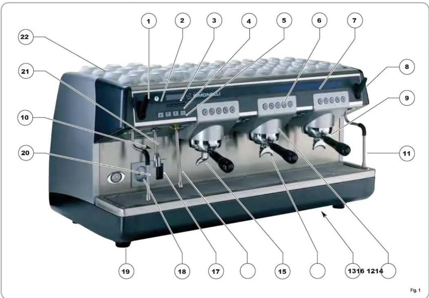
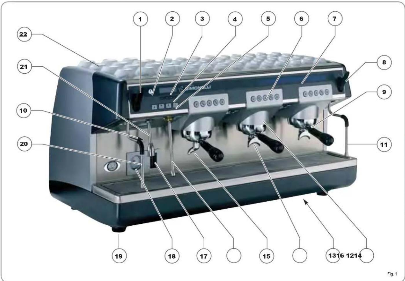
1. DESCRIPTION Vip Plus-V - Esse
text_image
1 2 3 4 5 6 7 8 9 10 20 21 22 1316 1214 Fig. 1KEY
1 Steam knob
2 Programming key (Vip Plus only)
3 LCD Display (Vip Plus only)
4 Functions buttons (Vip Plus only)
5 Selections buttons
6 Delivery unit buttons
7 Electronic displays
8 Steam knob
9 Filter-holder
10 Data plate
11 Manual steam nozzle
12 Delivery unit
13 Main switch
14 2 coffees spout
15 1 coffee spout
16 Automatic steam nozzle (optional in V and ESSE version)
17 Optical level
18 Pressure Gauge
19 Adjustable foot
20 Manual steam nozzle
21 Hot water nozzle
22 Electric cup-warmer (steam cup-warmer, optional)
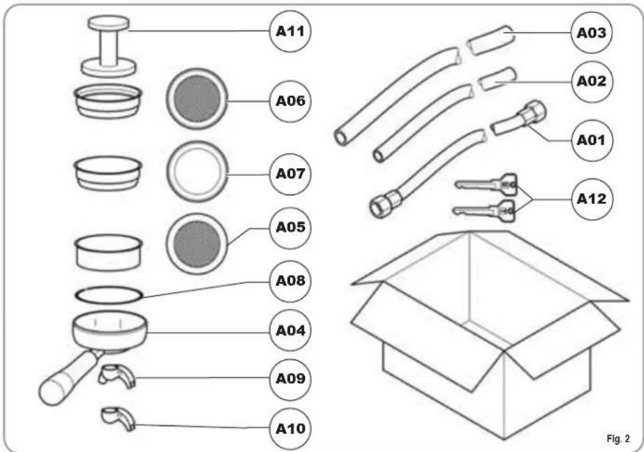
1.1 ACCESSORIES LIST
text_image
A11 A06 A07 A05 A08 A04 A09 A10 A03 A02 A01 A12 Fig. 2| CODE DESCRIPTION 2 GROUPS 3 GROUPS 4 GROUPS | |||||
| A01 Filling tube 38 " 1 1 1 | |||||
| A02 Unit tub draining tube ∅ 20 mm - I. 150 cm 1 1 1 | |||||
| A03 Worktop draining tube ∅ 25 mm - I. 150 cm 1 1 1 | |||||
| A04 Filter-holder 3 4 5 | |||||
| A05 Double filter 2 3 4 | |||||
| A06 Single filter 1 1 1 | |||||
| A07 Blind filter 1 1 1 | |||||
| A08 Spring 3 4 5 | |||||
| A09 Double delivery spout 2 3 4 | |||||
| A10 Single delivery spout 1 1 1 | |||||
| A11 Coffee presser 1 1 1 | |||||
| A12 | ‘U’ and ‘T’ keys (Plus model only) | 1 | 1 | 1 | |
2. SAFETY PRESCRIPTION

This book is an integral and essential part of the product and must be given to the user. Read this book carefully. It provides important information concerning safety of installation, use and maintenance. Save it carefully for future reference.

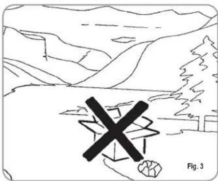
After unpacking, make sure the appliance is complete. In case of doubts, do not use the appliance, but consult a qualified technician. Packaging items which are potentially dangerous (plastic bags, polystyrene foam, nails, etc.) must be kept out of children's reach and must not be disposed of in the environment.

RISK OF POLLUTION
natural_image
Simple line drawing of a mountainous landscape with a cross symbol overlay (no text or symbols present)
Before connecting the appliance make sure the rating plate data correspond with the mains. This plate is on the front panel at the top right hand side of the appliance. The appliance must be installed by qualified technicians in accordance with current standards and manufacturer's instructions.
The manufacturer is not liable for any damage caused due to failure to ground the system. For the electrical safety of the appliance, it is necessary to equip the system with the proper grounding. This must be carried out by a qualified electrician who must ensure that the electric power of the system is sufficient to absorb the maximum power input stated on the plate.

natural_image
Simple white cross symbol on dark gray circular background, no text or numbers presentFig. 4

In particular you must ensure that the size of the wiring cables is sufficient to absorb power input.
The use of adapters, multiple sockets or extensions is strictly forbidden. If they prove necessary, call a fully qualified electrician.

When installing the device, it is necessary to use the parts and materials supplied with the device itself. Should it be necessary to use other parts, the installation engineer needs to check their suitability for use in contact with water for human consumption.

The machine must be installed in compliance with the local health standards in force for plumbing systems. Therefore, contact an authorized plumber.

The device needs to be supplied with water that is suitable for human consumption and compliant with the regulations in force in the place of installation. The installation engineer needs confirmation from the owner/manager of the system that the water complies with the requirements and standards stated above.

For appliances powered at 220 -230 V, the maximum impedance from the mains must be no higher than 0.37 Ohm.

This appliance must only be used as described in this handbook. The manufacturer shall not be liable for any damage caused due to improper, incorrect and unreasonable use.

This appliance is not suitable for use by children or persons with reduced physical, sensory or mental capabilities, or by persons with a lack of experience or knowledge, unless supervised or given instructions.

The maximum and minimum storage temperatures must fall within a range of [-5, +50]^ .

The operating temperature must be within the range of [+5, +35]^ .

SIMONELLI

At the end of installation, the device is switched on and taken to rated operating conditions, leaving it in a state in which it is "ready for operation".
The device is then switched off and the whole hydraulic circuit is bled of the first lot of water in order to remove any initial impurities.
The device is then refilled and taken to rated operating conditions.
After reaching the "ready for operation" condition, the following dispensing operations are carried out:
- 100% of the coffee circuit through the coffee dispenser (for more than one dispenser, this is divided equally);
- 100% of the hot water circuit through the water dispenser (for more than one dispenser, this is divided equally);
- opening of each steam outlet for 1 minute.
At the end of installation, it is good practice to draw up a report of the operations.

Basic rules must be observed when using any electric appliance.
In particular:
• do not touch the appliance when hands or feet are wet;

CAUTION RISK OF ELECTRIC SHOCK
• do not use the appliance when barefoot;
• do not use extensions in bath or shower rooms;
- do not pull the supply cord out of the socket to disconnect it from the mains;
• do not leave the appliance exposed to atmospheric agents (rain, sun, etc.);
• do not let the appliance be used by children, unauthorised staff or staff who have not read and fully understood the contents of this handbook.

During installation, the mains power system needs to be equipped with a disconnector switch to cut off each phase.

Before performing any maintenance operations, the authorised service engineer must switch off the machine and open the phase disconnector.

For all cleaning operations comply exclusively with the instructions given in this booklet.
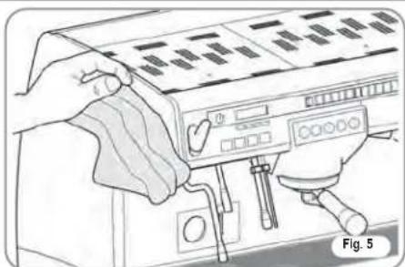
natural_image
Illustration of hands operating a coffee machine with control panel and keyboard (no text or symbols visible)
If the appliance breaks down or fails to work properly, switch it off. Any intervention is strictly forbidden. Contact qualified experts only.
Repairs should only be made by the manufacturer or authorized service centres. Only original spare parts must be used. Failure to observe the above, could make the appliance unsafe.

For installation, the qualified electrician must fit an omnipolar switch in accordance with the safety regulations in force and with 3 (0,12) or more mm (in) between contacts.

To avoid dangerous overheating, make sure the supply cord is fully uncoiled.

Do not obstruct the extraction and/or dissipator grids, especially of the cup warmer.

The user must not replace the appliance supply cord. If the cord is damaged, switch off the appliance and have a qualified technician change the cord.

Single-phase appliances with current above 15 A and three-phase appliances sold without plugs are directly wired to the mains power and therefore, it is not possible to use a plug.

If no longer using the appliance, we recommend making it inoperative; after removing the plug from the mains electricity, cut the power supply cable.

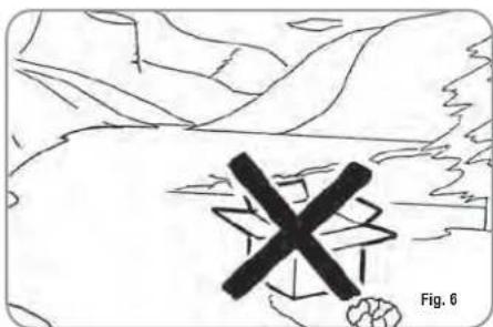
CAUTION RISK OF POLLUTION

Do not dispose of the machine in the environment: to dispose of the machine, use an authorised centre, or contact the manufacturer for relative information.
text_image
X Fig. 6
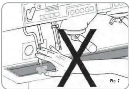
CAUTION RISK OF INTOXICATION

Use the steam nozzle with care and never place hands below the jet of steam. Do not touch the nozzle immediately after use.
natural_image
Illustration of a hand operating a medical device with a black X symbol (no text or symbols present)
CAUTION RISK OF BURNS OR SCALDING

We remind you that before carrying out any installation, maintenance, unloading or adjustment operations, the qualified operator must put on work gloves and protective footwear.

The maximum noise disturbance level is lower than 70db.

If the pipe connecting to the mains water is replaced the old pipe must never be re-used.

CAUTION
INFORMATION TO THE USERS
Under the senses of art. 13 of Law Decree 25th July 2005, n. 151 "Implementation of the Directives/ Guidelines 2002/95/CE, 2002/96/CE and
2003/108/CE, concerning the reduction of the use of dangerous substances in electric and electronic equipment, as well as the disposal of wastes".
The symbol of the crossed large rubbish container that is present on the machine points out that the product at the end of its life cycle must be collected separately from the other wastes. The user for this reason will have to give the equipment that got to its life cycle to the suitable separate waste collection centres of electronic and electrotechnical wastes, or to give it back to the seller or dealer when buying a new equipment of equivalent type, in terms of one to one. The suitable separate waste collection for the following sending of the disused equipment to recycling, the dealing or handling and compatible environment disposal contributes to avoid possible negative effects on the environment and on the people's health and helps the recycling of the materials the machine is composed of. The user's illegal disposal of the product implies the application of administrative fines as stated in Law Decree n.22/1997" (article 50 and followings of the Law Decree n.22/1997).
3. TRANSPORT AND HANDLING
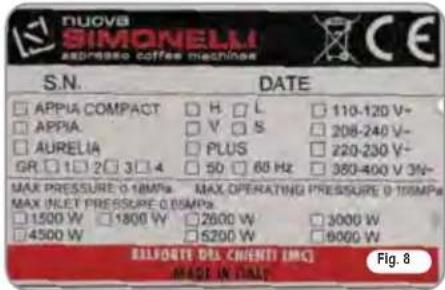
3.1 MACHINE IDENTIFICATION
Always quote the machine serial number in all communications to the manufacturer, Nuova Simonelli.
text_image
NUOVA SIMONELM expresso coffee machines S.N. DATE □ APPUA COMPACT □ APPIA □ AURELIA GR □ 1 □ 2 □ 3 □ 4 □ H. □ L □ V. □ S □ PLUS □ 50 □ 60 Hz □ 110-120 V- □ 208-240 V- □ 220-230 V- □ 380-400 V 3V~ MAX PRESSURE: 0-18MPa MAX OPERATING PRESSURE: 0-10MPa MAX INLET PRESSURE: 0.05MPa □ 1500 W □ 1800 W □ 2600 W □ 3000 W □ 4500 W □ 5200 W □ 6000 W BALFONTE DHL CHIENTI (MC) MADE IN TALY Fig. 83.2 TRANSPORT
The machine is transported on pallets which also contain other machines - all boxed and secured to the pallet with supports.
Prior to carrying out any transport or handling operation, the operator must:
- put on work gloves and protective footwear, as well as a set of overalls which must be elasticated at the wrists and ankles.
The pallet must be transported using a suitable means for lifting (e.g., forklift).
3.3 HANDLING

CAUTION
RISK OF IMPACT OR CRASHING
During all handling operations, the operator must ensure that there are no persons, objects or property in the handling area.
The pallet must be slowly raised to a height of 30 cm (11,8 in) and moved to the loading area. After first ensuring that there are no persons, objects or property, loading operations can be carried out.
Upon arrival at the destination and after ensuring that there are no persons, objects or property in the unloading area, the proper lifting equipment (e.g. forklift) should be used to lower the pallet to the ground and then to move it (at approx. 30 cm (11,8 in) from ground level), to the storage area.

CAUTION
RISK OF IMPACT OR CRASHING
Before carrying out the following operation, the load must be checked to ensure that it is in the correct position and that, when the supports are cut, it will not fall.
The operator, who must first put on work gloves and protective footwear, will proceed to cut the supports and to storing the product. To carry out this operation, the technical characteristics of the product must be consulted in order to know the weight of the machine and to store it accordingly.
4. INSTALLATION AND PRELIMINARY OPERATIONS
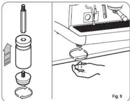
After unpacking, assess that the machine and its accessories unit are complete, then proceed as follows:
- place the machine so that it is level on a flat surface;
- assemble its supporting feet by inserting the insert into the cylindrical unit;
- twist the rubber foot into the screw thread inside the unit;
- screw the whole assembled unit into the allotted setting for the machine's adjustable feet;
• level the machine by regulating the adjustable feet;
NOTE: the unit grooves have to face upwards, as shown in the following illustration.
natural_image
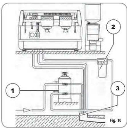
Diagram showing a mechanical device with a spring and a hand holding a tool, alongside its side view of a kitchen sink (no text or symbols present)It is advisable to install a softener (1) and then a mesh filter (2) on the external part of the plumbing system, during preliminaries and after levelling the machine.
In this way impurities like sand, particles of calcium, rust etc will not damage the delicate graphite surfaces and durability will be guaranteed.
Following these operations, connect the plumbing systems as illustrated in the following figure.

IMPORTANT
Recommended mains pressure for the water is [2.3] bar.

WARNING
Avoid throttling in the connecting tubes. Assess that the drain pipe (3) is able to eliminate waste.
text_image
1 2 3 Fig. 10KEY
1 Softener
2 Mesh filter
3 Drain ∅ 50 mm
NOTE: For a correct functioning of the machine the water works pressure must not exceed 4 bars.
Otherwise install a pressure reducer upstream of the softener; the internal diameter of water entrance tube must not be less than 6mm (38").

CAUTION RISK OF SHORT CIRCUITS
The machine must always be protected by an automatic omnipolar switch of suitable power with contact openings of equal distance or more than 3mm.
Nuova Simonelli is not liable for any damage to people or objects due to not observing current security measures.
Prior to connecting the machine to the electrical mains, assess that the voltage shown on the machine's data plate corresponds with that of the mains.
If it does not, carry out the connections on the basis of the available electrical line, as follows:
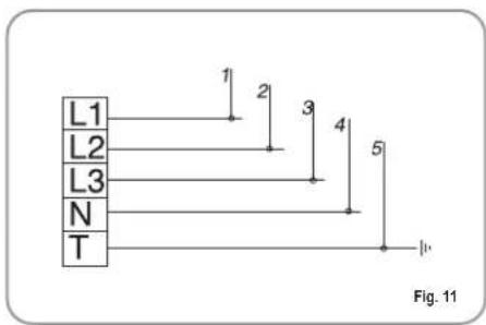
• for V 380 / 3 phases voltage +Neutral:
text_image
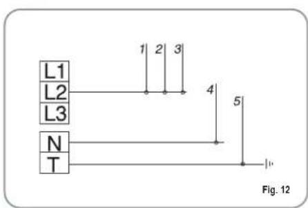
L1 L2 L3 N T 1 2 3 4 5 Fig. 11• for V 230 / monophase voltage
text_image
L1 L2 L3 N T 1 2 3 4 5 Fig. 12KEY
1 Black
2 Grey
3 Brown
4 Blue
5 Yellow-green
NOTE: At the start of the day's activities and in any case, if there are any pauses of more than 8 hours, then it is necessary to change 100% of the water in the circuits, using the relevant dispensers.
NOTE: In case of use where service is continuous, make the above changes at least once a week.
5. ADJUSTMENTS TO BE MADE BY A QUALIFIED TECHNICIAN ONLY
5.1 FILLING BOILER MANUALLY
NOTE: this operation must be carried out with the machine turned off.
All models _veciv are equipped with a level gauge to keep the water level inside the boiler constant.
When using the machine for the first time, it is advisable to fill the boiler by hand to avoid damaging the electrical resistor and turning on the electronic protection.
If this should happen, just turn the machine off and then start it up again to complete its loading procedure (see chapter "MACHINE FUNCTIONS MESSAGE – LEVEL ERROR").
To fill the boiler manually for the first time, proceed as follows:
- remove the worktop grid;
- turn the manual "A" level tap so that water will enter the boiler;
- once the maximum level has been reached, as indicated by the optical level, turn tap "A" off;
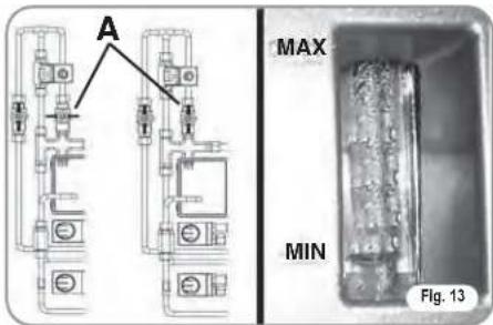
text_image
A MAX MIN Fig. 13- switch the machine on by placing the general switch on "I"; this will activate the level gauge which will automatically maintain the water level inside the boiler.
5.2 PRESSOSTAT/PUMP ADJUSTMENT
NOTE: this operation can be carried out while the machine is turned on.
To adjust the service pressure of the boiler, thus regulating the water temperature, according to the various functions and needs of the coffee desired, proceed as follows:
- remove the worktop grid cover;
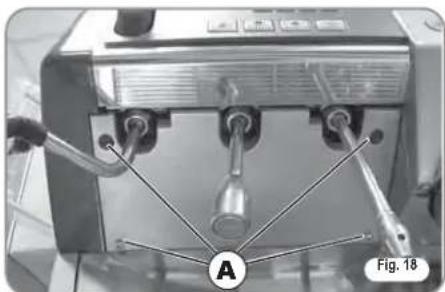
- remove the protective metal sheet by unscrewing the two side screws (A) as shown in the following illustration;
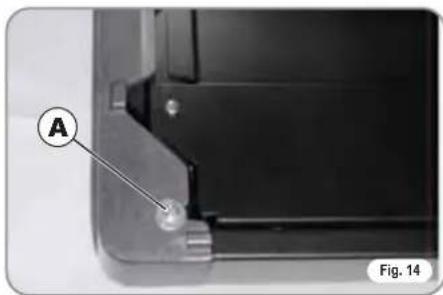
natural_image
Close-up of a mechanical component with labeled point A and Fig. 14 (no text or symbols beyond labels)- turn the pump registration screw, turning it clockwise to INCREASE and counter clock wise to DECREASE the pressure.
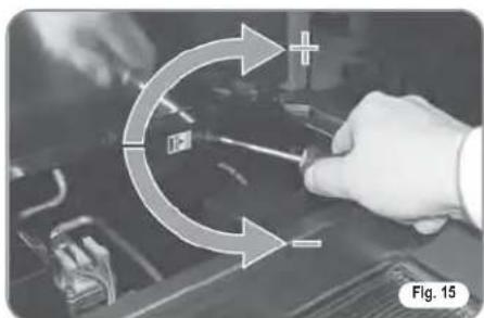
natural_image
Hand holding a tool with directional arrows indicating motion or force (no text or symbols)Advisable pressure: 1 - 1,4 bar (according to the kind of coffee).
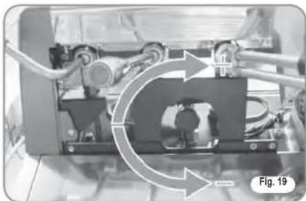
- turn the pump registration screw, turning it clockwise to INCREASE and counter clock wise to DECREASE the pressure.
natural_image
Close-up of a mechanical assembly with hoses and components, no visible text or symbolsAdvisable pressure: 9 bar.
• The set pump pressure is shown on the lower part of the gauge.
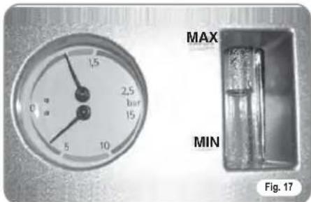
text_image
MAX MIN Fig. 17Once the adjustment operation has been completed, screw the protective metal sheet back into its setting and replace the worktop grid cover.
5.3 HOT WATER ECONOMISER ADJUSTMENT
NOTE: this operation can be carried out while the machine is turned on.
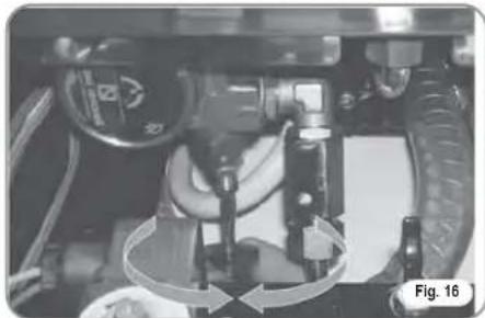
All models Another are equipped with a hot water mixer tap which adjusts the water temperature and optimises the system's performance. To adjust the hot water economiser, turn the registration knob as follows:
- unscrew the panel (A) situated below the steam and hot water levers;
- remove the panel;
- turn the registration knob.
natural_image
Close-up of a mechanical device with three ports and a labeled component (A), no visible text or symbols beyond labelsCLOCKWISE/COUNTER CLOCKWISE to INCREASE/DECREASE the hot water temperature;
natural_image
Mechanical assembly diagram showing rotating components with directional arrows (no text or symbols)- when the operation has been completed, screw the protective panel back on.
5.4 5.4 CLOCK BATTERY REPLACEMENT (only for the Vip Plus version)
The Vip Plus electronic control unit is equipped with a lithium battery to provide the clock with an approximately three-year autonomy period, after which replacing the battery may prove necessary.
In case the machine has remained unutilised for a long time, the clock can be blocked by proceeding as follows:
• with the machine off the display will read:
OFF
- press the ENTER key for 5 seconds; the display will read:
STOP CLOCK
The clock will start up again as soon as the machine is plugged in once more.

WARNING
Replacement of the lithium battery must be carried out EXCLUSIVELY by Qualified Technician.
Nuova Simonelli cannot be held liable for any damage to people or things due to non observance of the safety prescriptions described in this booklet.
5.5 PUSH-BUTTON PANEL REPLACEMENT
For correct functioning of the machine, personalising each button panel card at time of replacement is necessary; proceed as follows on the selectors placed on the card (on the key side).
| GROUP | sw1 | sw1 | sw1 | sw1 | sw1 | sw1 | sw1 | sw1 |
| Group 1 On | Off | Off | Off | On | Off | Off | ||
| Group 2 Off | On | Off | Off | Off | On | Off | ||
| Group 3 Off | Off | On | Off | Off | Off | On | ||
| Group 4 Off | Off | Off | On | Off | Off | Off |
5.6 ELECTRONIC DISPLAYS
Each model can come with the optional electronic displays which can be set by using the dating key. To set, follow the instructions provided in this booklet.
6. USE
Before starting to use the appliance, the operator must be sure to have read and understood the safety prescriptions contained in this booklet.
The Aurelia Vip Plus model is provided with an optional key management system of waiter keys and technician U key, so that different keys correspond to different functions. The waiter keys can access the normal working functions and can be displayed but not modified on the program menu (Ch.7). The technician U key allows you to access all the functions and to modify the parameters of the programming menu.
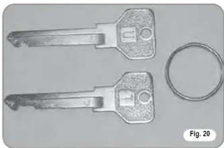
natural_image
Two metallic key-shaped objects with circular holes and a separate ring, labeled Fig. 20 (no text or symbols on the main objects)6.1 TURNING THE MACHINE ON
6.1.1 AURELIA VIP PLUS
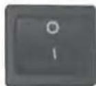
- Plug the machine in and position the main switch on "I".
- The state of the machine will be shown by the signal:

Fig. 21
• The unlit display will read:
OFF
NOTE: The machine is not operative in that the main switch only supplies the electronic card.

WARNING
For electronic card maintenance, turn the machine off by means of the external main switch or disconnect the plug.
MANUAL SWITCHING ON/OFF
Automatic On/Off NOT PROGRAMMED
NOTE: make sure that the general switch is always on the position "I".
The state of the machine will be shown
by the signal:

SWITCH ON: press the RESET key for 2
seconds, the buzzer will beep, the display will light up to indicate the release of the EPROM for about 1 second. The control unit will start up an auto diagnosis cycle to check the functions, all the selection keys will light up.Once the check is completed the display will read:
HEATING
with the day and time. When 110°C has been reached, the heating message will disappear and will be replaced by the words:
MACHINE READY
NOTE: on completion of the check up all the selection keys are activated.

WARNING
In case the auto diagnosis indicates error or malfunction, call an assistance centre; the operator MUST NOT intervene.
POWER OFF: press the RESET key for 2 seconds; the machine will turn off and the display will read:
OFF
Automatic On/Off PROGRAMMED
NOTE: make sure that the general switch is always on the position "I".
The state of the machine will be shown
by the signal:

The machine will SWITCH ON at the first programmed switch-on time (see the section entitled PROGRAMMING at the paragraph PROGRAMMING ON - OFF).
The control unit will perform an auto diagnosis of all functions and all of the selection keys will light up.
Once the diagnosis is complete, the display will read as follows:
HEATING
with the date and time. Once the temperature of 110^ C has been the word “Heating” will disappear to be replaced by:
MACHINE READY
NOTE: once the auto diagnosis has been completed all the keys are activated.

WARNING
In case the auto diagnosis indicates error or malfunction, call the assistance centre; the operator MUST NOT intervene.
The machine will SWITCH OFF at the first time set for stopping the coffee maker (see chapter on PROGRAMMING and paragraph on PROGRAMMING ON - OFF).
NOTE: the machine can be switched on or off manually as indicated in the previous paragraph.
6.1.2 AURELIA V/ESSE
SWITCHING ON: plug the machine in and position the main switch on "I" The state of the machine will be shown by the signal:

Fig. 22

WARNING
In case the auto diagnosis indicates error or malfunction, call the assistance centre; the operator MUST NOT intervene.
SWITCHING OFF: press the main switch into the "O" position to switch the machine and the signal off.
6.1.3 AURELIA VIP-V/ESSE WITH ELECTRONIC DISPLAYS (OPTIONAL)
SWITCHING ON: Plug the machine in and position the "A" switch on "I"; the machine will turn on. By pressing the "B" switch onto position "I" an illuminated display will turn on even when the machine is switched off.
A B
Fig. 23

WARNING
In case the auto diagnosis indicates error or malfunction, call the assistance centre; the operator MUST NOT intervene.
6.2
SELECTION CONFIGURATION
Set the desired function on the available keys placed above the filter-holders (see chapter "DESCRIPTION").
natural_image
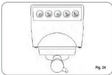
Line drawing of a medical or laboratory device with four circular indicators and a central dome, labeled Fig. 24 (no text or symbols on the device itself)BUTTONS KEY
(Selection configuration)

1 small coffee

2 small coffees

1 long coffee

2 long coffees

Continuous
6.3
MAKING COFFEE
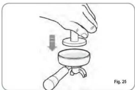
Unhitch the filter-holder and fill it with one or two doses of ground coffee depending on the filter used.
natural_image
Illustration of a hand using a magnifying glass to press a small object, labeled Fig. 25 (no text or symbols on the diagram itself)Press the coffee with the provided coffee presser, dust off any coffee residue from the rim of the filter (this way the rubber gasket will last longer).
Insert the filter in its unit.
Press the desired coffee button:

1 small coffee

2 small coffees

1 long coffee

2 long coffees
By starting up the coffee brewing procedure the unit's pump is activated and the unit's solenoid valve is opened.
By pressing it, the button will turn on and signal the operation
NOTE: when in pause, leave the filter-holder inserted in the unit so that it will keep warm. To guarantee the utmost thermic stability during use, the delivery units are thermo-compensated with complete hot water circulation.
6.4
USING STEAM

CAUTION RISK OF BURNS OR SCALDING
While using the steam nozzle, you must pay attention to not place your hands beneath it or touch just after it has been used.
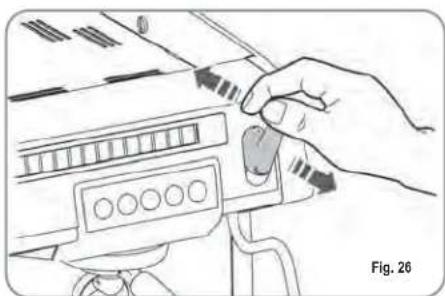
To use steam just pull or push the provided lever (Fig. 26).
By pulling it completely the lever will hold a position of maximum delivery; by pushing it, the lever will automatically give way.
The two steam nozzles are articulated to guarantee their easy use.
natural_image
Hand operating a device with control buttons and a scroll (no visible text or symbols)NOTE: Before using the steam wand, always bleed out any condensation for at least 2 seconds or according to the manufacturer's instructions.
6.5 MAKING CAPPUCCINO
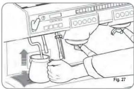
To obtain the typical cappuccino foam, immer-se the nozzle all the way into a container 1/3 full of milk (preferably cone-shaped). Turn on the steam. Before the milk starts to boil, pull the nozzle slightly up and lightly move it vertically across the surface of the milk. When you have completed the procedure, clean the nozzle carefully with a soft cloth.
natural_image
Illustration of a hand using a coffee machine to pour tea (no text or symbols visible)6.6 HOT WATER SELECTION
CAUTION RISK OF BURNS OR SCALDING
While using the hot water nozzle, pay careful attention not to place your hands beneath it or touch it just after it has been used.
This nozzle delivers hot water to make tea or herb teas.
Place a suitable container under the hot water nozzle (see Fig. 1, position 21).
Press the hot water selection button once

Make sure the button lights up.
Water will be delivered from the hot water nozzle for as long as the set time indicates.
NOTE: Hot water can be delivered at the same time as coffee.
6.7 TIMED STEAM NOZZLE
CAUTION RISK OF BURNS OR SCALDING
While steam is being delivered do not touch the nozzle with any part of the body, and have it always facing downwards towards the cup-holder grid.
It provides steam ejection to foam milk or to heat up other liquids.
Place a suitable container (see Fig. 1 position 16) under the automatic steam nozzle.
Press the steam selection button once

Make sure that the button lights up.
Steam will be ejected from the automatic steam nozzle.
Press it again to arrest delivery.
The Plus and V models provide an optional nozzle with a temperature probe which remains on until the beverage being heated reaches the set temperature.
7. PROGRAMMING
7.1 KEY
text_image
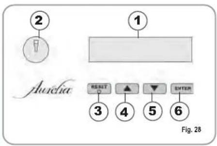
② ① Aurelia RESET ▲ ▼ ENTER ③ ④ ⑤ ⑥ Fig. 281 LCD Display.
2 Technician/waiter key lock.
3 RESET RESET key to turn the machine on and off and to exit menu.
45 CURSOR key: to scroll the menu and to increase and decrease values.
6 ENTER ENTER key: to access the menu.
LIST OF PROGRAMMABLE FUNCTIONS
AUTO.CLEAN.CYCLE
DOSE PROGRAM.
DELIVERY COUNT
ON-OFF PROGRAM.
CUP-WARMER PRO.
DATE/TIME
GRINDING
HISTORICAL ALARM
MAINTENANCE
LANGUAGE
TEMPERATURE
LIGHT ADJUST

Operation to be carried out EXCLUSIVELY by a Qualified Technician. Adjustment by NON qualified technicians can invalidate the guarantee.
7.2
PROGRAMMING AURELIA VIP PLUS
To access the programming units, proceed as follows:
NOTE: the procedure can be carried out with the machine on.
- Insert the key marked U (see chapter "USE") in the provided keyhole.
AUTOMATIC CLEANING CYCLE
(function also available with T visualization key)
- Press the key to access program; the display will read:
AUTO.CLEAN.CYCLE
- Press ENTER and the display will read:
AUTO.CLEAN.CYCLE SELECT
- The central key in each unit will begin to flash on and off. Insert the blind filter (fig 2 A07) into the filter-holder, add half a dose of PULICAFF and attach the filter-holder into the unit where you intend to carry out the automatic cleaning cycle. Carrying out a cleaning cycle in more than one unit at a time is possible.
- Press the key to start the unit automatic cleaning cycle. The display will read:
AUTO.CLEAN.CYCLE IL
where 1L indicates that the cleaning cycle has been activated within the 1st unit. Once the cycle of 15 deliveries of 5 seconds each, with a 10-second pause between each delivery, has been completed the selected unit key will begin to flash on and off again and the display will read.
RINSE
- Eliminate any residues of PULICAFF from the blind filter and press 📋 the rinsing cycle starting up key of the unit or units where the cleaning cycle has been effected. The letter R will remain on the display like the key 📋. Once the rinsing cycle of the selected unit or units has been completed, the display will read.
MACHINE READY
PROGRAMMING DOSES
- Press the ▼ key to access the programming; the display will read:
PROGRAM. DOSES
- Press ENTER and the display will read:
PROGRAM. DOSES SELECT
All the programmable keys will start to flash on and off.
- Press the coffee key you wish to program; the display will read:
VOLUME C.C:
Followed by the dose amount already set by the manufacturers.
- Vary the dose, by pressing the buttons

- By pressing the coffee key you want to program, delivery will be started up (in the meantime all the other keys will turn off).
- Select the dose of delivered coffee and then press the coffee key you want to program again.
- The display will show the new dose amount which can still be changed by means of the keys.
- Going on to another selection or pressing the key The set coffee key will turn off.
HOT WATER
- Press the button and make sure that it lights up.
The display will read:
SECONDS
followed by the value already set by the manufacturers.
Press the keys to vary the
hot water delivery time.
- If a new sampling is desired press the button again.

Delivery starts. When the desired dose has been reached press the button again
- The display will show the new dose value set which can still be changed by pressing the keys.
- Press the key or go on to a further selection to terminate the operation. The button will turn off.
TIMED STEAM
- Press the button and make sure it lights up. In those models provided with a temperature probe (optional) the control unit automatically recognizes the presence of the
probe and the display will read:
STEAN. TEMP. °C
followed by the temperature set previously by the manufacturer.
Press the ▼ ▲ keys to vary the temperature of the beverage you want to heat. When the desired temperature has been reached, the steam delivery will automatically stop.
- In the standard version (without temperature probe), on pressing the the display will read:
STERN SECONDS
followed by the amount already set by the manufacturers.
Press the ▼ ▲ keys to vary the steam delivery time.
- If a new sampling is desired press the button again.

Delivery starts. When the desired dose has been reached press the button again
- The display will show the new value set which can still be changed by pressing the
- Press the ENTER key or go on to a further selection to terminate the operation.
The button will turn off.
TRANSFERRING DOSES
- When the display reads:
PROGRAM DOSES SELECT
transferring the set dose to other units is possible by pressing the ▼ key.
The display will read:
DOSES TRANSFER SELECT GROUPS
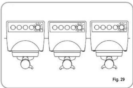
at this point all the delivery buttons belonging to each individual unit will flash as illustrated in Fig. 31.
- By selecting the 📁 continue key once on the first unit (the key will stop flashing but remain lit up), the set values will be transferred from the first unit to the other units.
natural_image
Three identical illustrations of washing machines with sun patterns, no text or symbols present- Press the ENTER key to confirm. At this point the display will read:
PROGRAM DOSES SELECT
- Press the RESET or the key to exit without confirmation.
TANDARD DOSES
- When the display reads:
DOSES TRANSFER SELECT GROUPS
we mean to recall the standard dose values.
- Press the ▼ key. The display will read:
DEFAULT SETTING SELECT GROUPS
Once again the delivery buttons will begin to flash (see. Fig. 29) on and off.
- Select one or more continue keys (the key or keys selected will remain lit up).
The key or keys will recall the selected unit's standard doses.
- Press the ENTER key to confirm.
The display will read:
PROGRAM DOSES SELECT
NOTE: all the selections can be programmed for a maximum of two minutes; after that time a flashing message will appear on the display saying:
ERROR
DELIVERY COUNT
- The display will read:
DELIVERY COUNT
- By pressing the ENTER key the display will read:
SELECTION TOTAL
- All the delivery keys will start to flash on and off. By pressing one of the delivery keys the amount of the deliveries made will be visualised.
• To set the counter back to zero, press the key.
NOTE: The continuous coffee equals one delivery.
- Press ENTER to access waiter counts (if provided).
- Press the ▼ key and the display will read:
GROUP TOTAL
All the units' small coffee keys will begin to flash on and off.
Example:
By selecting one of the first unit's keys (the selected key will remain lit up) the display will read:
GROUP TOTAL GR.1 DELI.
which means the total amount of deliveries for that unit.
• To set the counter back to zero press RESET
• To access the waiter counter press ENTER.
- When the display reads:
GROUP TOTAL
press ▼ and the display will read:
MACHINE TOTAL
This indicates the total amount of deliveries made.
• To set the counter back to zero press. RESET
• To access total counts per waiter press ENTER
- By pressing the ▼ key the display will read:
CLEANING COUNTER
To access the automatic cleaning counter press .ENTER
- The 📄 keys will flash on and off; by pressing the unit key the number of cleaning cycles effected will appear. By pressing the key (reset) for 5 seconds the counter will be set back to zero.
ON/OFF PROGRAM.
• The display reads:
ON-OFF PROGRAM
- By pressing the ENTER key, the display will read:
MONDAY ON 07:30 OFF 23:30
where the ON and OFF values indicate when the machine will turn on and off.
- Press to change the day forward and backward.
-
Press to vary the programmed starting up time (the message ON 07:30 will start to flash on and off).
-
Use the keys to vary the starting up time.
- Press ENTER to confirm and to go on to the programmed switching off time (the message OFF 23.30 will start to flash on and off).
- Use the ▼ keys to vary the switching off time.
- Confirm by pressing ENTER .
- To de-activate the on/off function on weekly day-off, press. RESET
The display will read:
DRY OFF
(to reinstate, press RESET)
After the word SUNDAY, by pressing again, a beep will signal that you have come to the following page.
CUP-WARMER PROGRAMMING
• The display will read:
CUPJARTER PROG.
- By pressing the ENTER key, the display will read (for example):
ONOS OFF60
The words ON05 will begin to flash on and off; use the ▼▲ keys to vary the opened cup-warming time (anywhere between 0 and 60 minutes.
- Press to confirm and to set the cup-warmer at OFF, which includes from 0 to 60 minutes.
NOTE: By programming one of the two ON/OFF values at 0, will automatically exclude the function.
When the cup-warmer has been set, the button will start to slowly flash.
- Press the ENTER key to go on to the next page.
DATE/TIME PROGRAMMING
• The display will read:
DATE/HOUR
- By pressing the ENTER key, the display will read for example:
MONDAY 08:22 08- AAG-03
The times will start to flash on and off.
- Vary the hours and the minutes by using the keys ▼.
- Confirm by pressing the ENTER key.
Once the hours and the minutes have been varied press again and vary the day, the month and the year by using the same procedure as described above.
On completion press ENTER to go on to the next page.
GRINDING CONTROL PROGRAMMING
The Aurelia Plus is equipped with an electronic system to control delivery times according to the coffee grinding fineness.
• The display will read:
GRINDING
- By pressing the ENTER key on the line above, it will read:
DELIVERY TIME
and in the line below, the current setting
DELIVERY TIME SET
DELIVERY TIME NOT SET
- Use the keys to change the setting; use the RESET key to quit the function without confirming, or press the key ENTER to confirm.
• If the delivery time display reads:
DELIVERY TIME SET
- then the sub-page for grinding control values is skipped, to pass directly to the following page:
FAULTS HISTORY
If the delivery time display is on when a deli-
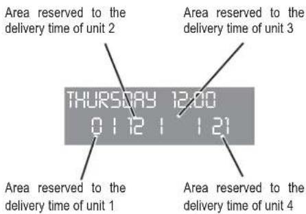
very is started - unless with the Continuous function - the bottom line of the display will show the delivery time (or times if more than one unit is delivering).
Each group has an area of the bottom line: the area on the left is for unit 1; the area alongside it is for unit 2 and so on, until the area on the far right, which is for unit 4.
The different areas are separated by vertical bars; if a group is not delivering, the area is empty.
Here below is an example: unit 1 is delivering (it has just started and 0 seconds have passed); unit 2 has been delivering for 12 seconds and unit 4 is delivering (it has been delivering for 21 seconds).
text_image
Area reserved to the delivery time of unit 2 THURSDAY 12:00 01121121 Area reserved to the delivery time of unit 1 Area reserved to the delivery time of unit 4If the time is confirmed:
DELIVERY TIME NOT SET
the machine passes to the grinding control value settings.
- By pressing the ENTER key the display will read as follows:
1 ESPRESSO 00-40 2 ESPRESSO 00-40
where 00-40 indicates the maximum time (in seconds) allotted for the delivery of a sample amount of coffee, equal to 10cc for a single coffee and 30cc for a double coffee.
The first value will begin to flash on and off; modify by using the ▼▲ keys.
To confirm press the ENTER key.
- Press the ENTER key again to go on to the next value. To modify the previous value, proceed as described above.
NOTE: If the system detects a delivery time (of the sampled amount) inferior to the programmed minimum, the display will read:
COARSE GRINDING
(See chapter called "MACHINE FUNCTION MESSAGES") which means you have to adjust the coffee grinder to reduce the grain.
If the system detects a delivery time (of the sampled amount) superior to the programmed maximum, the display will read:
FINE GRINDING
(See chapter called "MACHINE FUNCTION MESSAGES") which means you have to adjust the coffee grinder to increase the grain. By setting the values at 00-40, the function is excluded.
- On completion press ENTER to go on to the next page
HISTORICAL ALARM VISUALISATION
• The display will read:
FAULTS HISTORY
- By pressing the ENTER key, the display will read:
ERROR 01
- Pressing the ▼ key, allows you to scroll down the ten previous alarms saved in the memory. After the tenth alarm, by pressing the ▼ key again you can go on to the next page.
MAINTENANCE PROGRAMMING
• The display will read:
MAINTENANCE
- By pressing the key, the display will read:
DELIVE. 10000 01 GENNUARY 2005
- Use the values. - keys to set both
- Use the key to confirm.
Once the set delivery limit or the set maintenance date have been reached, the display will visualize the message:
RAINTENANCE
Insert the "U" key (see chapter "USE") and set the display back to zero by pressing the key.
To go on to the next page, press the key.

SELECTING THE DESIRED LANGUAGE
• The display will read:
LANGUAGE
- Press the key to visualise the language already set. Choose the desired language by using the keys.
• To confirm press . ENTER
TEMPERATURE UNITY MEASURE SELECTION
• The display reads:
TEMPERATURE
- By pressing ENTER, the display will read
CELSIUS
0
FAHRENEIT
- Press to modify the measures unit setted.
- Press ENTER to confirm.
KEYBOARD LIGHTING ADJUSTMENT
• The display reads:
LIGHT ADJUSTMENT
- By pressing ENTER, key, the display will read:
KEYS X DISPLAY Y
- With the KEYS light X blinking.. Select the value of desired brightness choosing from a minimum value of 1 to a maximum of 6 by using the keys.
- Confirm by pressing ENTER
- The temperature DISPLAY value 9 blinks and with keys it is possible to set the display lighting 9 from a minimum value of 1 to a maximum of 3.
- Confirm by pressing ENTER
• The display will visualize the message:
LIGHT ADJUSTMENT
7.3 PROGRAMMING AURELIA V
DOSE PROGRAMMING
To access the programming units, proceed as follows:
NOTE: the procedure can be carried out with the machine on.
- To access the dose programming state of each unit press the first unit's continuous delivery (i) key for 5 seconds.
• The delivery keys will begin to flash on and off. - Access into the first unit's programming allows you to set the machine's function parameters.
COFFEE DOSE PROGRAMMING
To program the relative water doses for one of the delivery keys, proceed as follows:
- fill the filter-holder with the correct dose of coffee (the filter-holder can be single or double depending on the key you wish to program).
- Insert the filter-holder into the unit.
- Press one of the delivery buttons (see illustration):

The delivery will start; once the desired amount has been reached, press the continuous 🔒 key.
• The delivery will stop and the chosen dose key will turn off (the other keys will continue to flash).
- Press the continuous key to exit programming or to continue programming other dose keys.
NOTE: This procedure is usable on all the machine units except if carried out one at a time; the other groups can carry on normally.
HOT WATER PROGRAMMING
- Access the programming according to the relative procedure.
- Press the hot water selection key
• Hot water delivery will start. - Establish the desired hot water dose and press the key again .
- Press the continuous 🔒 key to exit the programming or to continue programming other selection keys.
Technician: To enable the pump while hot water is being dispensed, enter the programming mode for the first dispensing group then press the continual button for the second group.
- To change the settings, it is sufficient to press the hot water button: if the button is not lit, the pump will not be enabled while hot water is being dispensed; if the button is lit while hot water is dispensed, the pump will be activated.
- Press the continual button for the second dispensing group to confirm the setting.
TIMED STEAM PROGRAMMING
- Access the programming according to the relative procedure.
- Press the steam selection key
- Steam ejection will start.
- Establish the desired dose of steam and press the key again.
- Press the continuous 📄 key to exit the programming or to continue programming other selection keys.

AUTOMATIC CUP-WARMER PRO- GRAMMING
- Access the programming according to the relative procedure.
- Press the cup-warming selection key
- The delivery keys of the first and second unit will respectively signal the allotted automatic switching on and off times while the continuous keys of the first and second units will flash on and off.
As described in the chart, each delivery key has an associated value, the starting up time of the cup-warmer is given by adding up the values of the first unit's lit-up keys. The same counting method is used for the cup-warmer switching off time with the keys of the second unit.

| Keys | 1° GROUP(time ON) | 2° GROUP(time OFF) |
| 2 minutes | 5 minutes | |
| 4 minutes | 10 minutes | |
| 8 minutes 20 | minutes | |
| 16 minutes 40 | minutes |
- Access the programming of the first group according to the relative procedure.
- Press the second unit continuous key (the key will light up).
- Press the second unit 1 small coffee key.

NOTA: If the 1 small coffee 📋 key is lit up, the pump will start up during the level. If the 1 small coffee 📋 key is not lit up, the pump will not start up during the level.
- Press the second unit continuous key.
In this way the selected pump setting is stored.
• To exit the programming, press the first unit continuous 🔒 key.
NOTE: The settings will be saved even when exiting the first unit programming directly.
ADJUSTING KEYBOARD LIGHTING INTENSITY
- Access the programming of the first group according to the relative procedure.
- Press the second unit continuous delivery key.
• The second unit 2 long coffees delivery key will flash on and off.
- Press the key more than once to vary the light intensity.
NOTE: You can set a maximum of five different degrees of light intensity.
• To store the set light intensity values in the memory, press the second unit continuous delivery key.
- To exit the programming, press the first unit continuous delivery key
NOTE: The settings will be saved even when exiting the first unit programming directly.
STEAM NOZZLE WITH TEMPERATURE PROBE (OPTIONAL)
- Make sure the temperature probe is connected to the control unit.
- The temperature value can be planned by sampling or manually depending by the types of memorization planned in the parameter setting section and value goes from a minimum of 50^ to a maximum of 95^ .
- By pressing the key of the second group is possible to chose if you wont set the steam temperature value manually or by sampling.
- When you enter in this part of the menu, the key of the second group is switched on.
- By pressing the key of the second group, it is possible to change the way in which settings are stored to memory.
- Press the continuous delivery key (3) for the 2nd unit to memorise the temperature value input mode.
Sampling:
• After entering in the program of the first group, put a jag with milk under the steam wand and press the key, the delivery of steam will start.
- By pressing again the key, or if it is reached the maximum temperature, the control board memorizes the temperature reached.
Manually:
• After entering in the program of the first group, press the keys of the first group, keys of the first and second group show the temperature starting from a minimum value of 50^ C.
- At every key has an value:
- Sum together the value associated to the relevant lit key to a minimum value of 50^ to obtain the temperature setting.
- If the key is lit, it is necessary to add the reference value, while it is not required if the key is not lit.
- By pressing again the key the value is planned and the machine came back to the general programming.
This way of setting doesn't use the delivery of steam.
• To escape from the program and save the setting, press the continuos key of the first group.
Technician:
- In this steam temperature setting is possible to plan the offset value, from -15^ to +15^ , to obtain the correct temperature value.
-
By pressing the key of the first group, is showed the offset value setted: the way to show is the same of the way to show the final steam temperature.
-
The keys of the first group show a value from 0 to 15^ C , the key of the second group show the offset sign:
- it is switched on the value is POSITIVE, if the key is switched off is NEGATIVE.
- By releasing the key of the first group, you memorize the value and came back to the steam temperature setting.
STANDARD DOSE PROGRAMMING
- Setting predetermined values for the four doses of the first delivery unit is not possible. To do so, you must:
- Press the first unit continuous delivery key and keep pressing it for at least 8 seconds, until the flashing delivery keys of the first unit turn off.
• The standard doses are illustrated in the following table:
| 40 cc | 60 cc | 50 cc | 85 cc | 9 sec. | 0 sec. |
NOTE: A time of 0 seconds for water and steam give way to their continuous functioning.
DOSE COPYING
This procedure must be carried out for each unit individually by pressing the continuous delivery key of the unit you desire to copy the doses onto and keep pressing it for at least 8 seconds, until the flashing delivery keys turn off
AUTOMATIC CLEANING CYCLE
• To enter in the automatic cleaning cycle, you must switch off the machine and switch on the machine holding pressing the hot water and cup warmer keys during the initial Lamp-test. At the end of the Lamp-test, starts to blinking the and keys and the (one long coffee) keys of each groups.
- By pressing the ⚙key starts the cleaning cycle in the group selected. When the cleaning cycle is finished, is possible to begin the rinsing cycle in the same group, by pressing again the ⚙key.
- If you want make the rinsing cycle in an other time it's enough to switch off the machine: the control board memorizes the cleaning cycles that you must end. With the next turn on, the control board will enter automatically in the cleaning cycle, without pressing the [icon] and [icon] keys.
- By pressing the 📄 and 📋 keys for 2 seconds you escape from the cleaning cycle in case there are not cycles to end, otherwise the 🔊 keys of the group, in that you must finish the rinsing cycle, remain with blinking.
- By holding pressing the 📄 and 📄 keys for other 2 seconds you force the escape from the cleaning cycle by resetting the rinsing cycle.
- If the cleaning and the rinsing cycle is ended, the key of the group switch off; if there are no cycles to finish, the machine return ready.
7.4 PROGRAMMING AURELIA ESSE
DOSE PROGRAMMING
In the Aurelia Esse version only the doses of water and timed steam can be programmed. To access the programming state you must:
- press the cup-warming key seconds. for five
• The selection keys and the 1 long coffee key belonging to the first unit will start to flash on and off while the other delivery keys of the other units will turn off.
HOT WATER

- Once the programming state has been accessed, by pressing the key.
hot water delivery will be activated; once the desired dose has been reached press the key again and the set delivery time
will be stored in the control unit.
TIMED STEAM

- Once the programming state has been accessed, by pressing the key,
hot water delivery will be activated; once the desired dose has been reached press the key again and the set delivery time
will be stored in the control unit.
ADJUSTING LIGHTING INTENSITY KEYBOARD
- Access programming according to the relative procedure.
- Adjust the light intensity of the keys by pressing the first unit's 1 long coffee key more than once.
NOTE: To exit programming press the key.

ACTIVATING LEVELLING PUMP
- Access programming according to the relative procedure.
- Press and keep pressing the 1 long coffee key belonging to the second unit.
• To set the activation of the pump during levelling, once the programming state has been activated, keep the second unit key pressed.
The second unit key will light up and by means of the first unit key, the pump setting will be visualized: if it is lit up the pump will function during levelling; if it is not lit up the pump will not be activated during levelling.
By pressing the first unit key the pump setting during levelling can be modified.
NOTE: to exit the programming press the key.

8. CLEANING AND MAINTENANCE
During maintenance/repairs, the parts used must be able to guarantee compliance with the safety and hygiene requirements envisaged for the device.
Original replacement parts can offer this guarantee. After repairs to/replacement of a part that comes into contact with foods or water, it is necessary to carry out a washing procedure or to follow the steps indicated by the manufacturer.
8.1 SWITCHING OFF THE MACHINE
To switch the machine off press the main switch and set the machine to the O energy position.
Aurelia Version
V/ESSE
Aurelia Version
Vip/V/ESSE
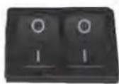
Fig. 30
8.2 CLEANING THE OUTSIDE OF THE MACHINE
The machine must be set to "O" power (switch off and disconnector open) before any cleaning operations are performed.

WARNING
It is not possible to clean the machine using water jets or standing it in water.

WARNING
Do not use solvents, chlorine-based products or abrasives.
Cleaning the work area: remove the worktop, lifting it up from the front and sliding it out. Remove the water collection dish underneath and clean everything with hot water and cleansers.
Cleaning the bottom: To clean all the chromium-plated areas, use a soft, damp cloth.
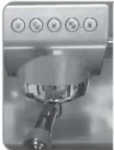
8.3
CLEANING THE STAIN- LESS COFFEE-HOLDERS
The stainless coffee-holders are situated under the delivery units, as shown in figure (31).
natural_image
Close-up of a stainless steel coffee maker's lever with five circular buttons (no visible text or symbols)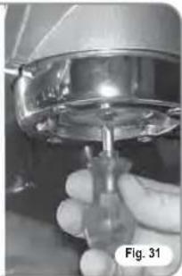
natural_image
Close-up of a hand holding a small mechanical component, possibly a valve or pump, with no visible text or symbols.NOTE: To clean proceed as follows:
- Turn the screw placed in the centre of the coffee-holder.
- Slide the coffee-holder out and check that its holes are not obstructed but clean.
- If obstructed, clean as described (Paragraph "CLEANING FILTERS AND FILTER-HOLDERS")
We recommend cleaning the coffee-holder once a week.
8.4
CLEANING THE UNIT WITH THE AID OF THE BLIND FILTER
The machine is pre-set for cleaning the delivery unit with a specific washing powder.
The machine will initiate washing cycle which consists in the circulation of hot water followed by regular breaks.
We recommend carrying out a washing cycle at least once a day with special cleansers.

CAUTION RISK OF INTOXICATION
Once the filter-holder has been removed, repeat delivery operations a few times to eliminate any cleanser residues.
To carry out the washing procedure, proceed as follows:
1) Substitute the filter with the delivery unit blind filter.
2) Fill it with two spoonfuls of special cleanser powder and insert it into the unit filter-holder.
3) Press one of the coffee keys and halt it after 10 seconds.
4) Repeat the procedure several times.
5) Remove the filter-holder and carry our a few deliveries.
8.5
CLEANING FILTERS AND FILTER-HOLDERS
Place two spoonfuls of special cleanser in half a litre of hot water and immerse filter and filter-holder (without its handle) in it leaving them to soak for at least half an hour. Then rinse abundantly with running water.
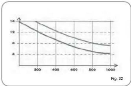
8.6 RESIN AND SOFTENER REGENERATION
To avoid scaling deposits in the boiler and in the heating exchangers, the softener must always be kept efficient. Therefore, the ionic resins must be regularly regenerated.
Regeneration times are established according to the quantity of coffee delivered daily and the hardness of the water utilised.
As an indication, regeneration times can be calculated on the basis diagram illustrated in Fig. 32.
line
| x | y1 | y2 | | ---- | ---- | ---- | | 0 | 14 | 14 | | 200 | 12 | 13 | | 400 | 10 | 11 | | 600 | 8 | 9 | | 800 | 6 | 7 | | 1000 | 4 | 5 |Regeneration procedures are as follows:
1) Turn the machine off and place a container large enough to contain at least 5 litres under tube E (Fig. 33).
Turn levers C and D from left to right; take the cap off by unscrewing knob and fill with 1 Kg normal kitchen salt (Fig. 34).
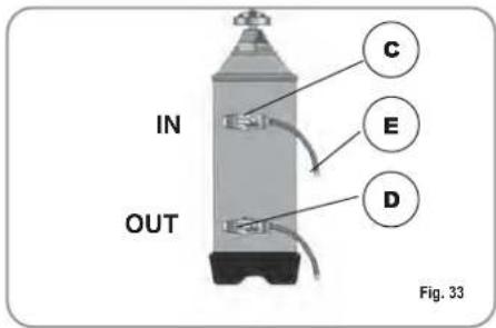
text_image
IN OUT C E D Fig. 33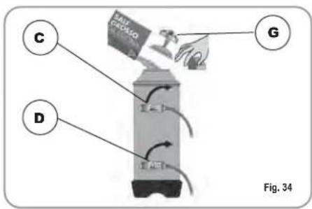
text_image
C D G Fig. 342) Put the cap back on and reposition lever C moving it towards the left (Fig. 35) and allowing tube F to discharge the salty water until it has been eliminated and the water becomes fresh again (about half and hour).
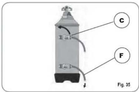
text_image
C F Fig. 353) Reposition lever D towards the left (Fig. 36).
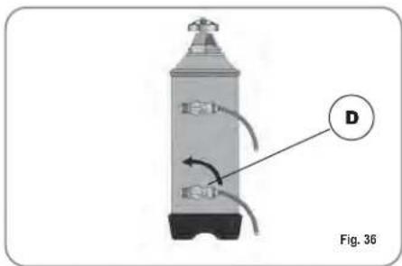
text_image
D Fig. 369. AURELIA PLUS MACHINE FUNCTION MESSAGES
| DISPLAY AND KEY INDICATIONS | CAUSE | EFFECT | SOLUTION | NOTES |
| DIAGNOSIS OF ERROR | At the time of the diagnosis the system presents faults within the control unit EPROM. | The machine will not heat and all its functions will be blocked. | ||
DELIVERY ERROR | On reaching delivery time limit (120 seconds) the doser doesn't send out its set commands. | The display indicator and the 'continuous' key belonging to the relative unit will flash on and off. | Press theRESETkey or one of the keys | |
DOSER ERROR | If the doser doesn't send out its set commands within the first three seconds from delivery onset. | If the delivery isn't manually halted, the maximum time limit (120 sec) will be blocked. | Press theRESETkey or one of the keys | |
 | If after 90 sec of machine functioning the water level is not re-established. | The display indicator will flash on and off. The pump is de-activated. The resistor and all the functions are halted. | Turn the machine off and then turn it on again. All its functions will be re-activated. | |
 | When the machine's temperature is higher than 130°C. | The display indicator will flash on and off and the resistor is de-activated. | The system will be re-established as soon as the temperature goes below 130°C. | The boiler is provided with a manual refitting safety thermostat; if the resistor is not re-established, call a qualified technician. |
| Incorrect electrical input caused by a malfunction in one of the machine charges. | The display reading will flash. The pump will switch off. The heating element and all other functions will be disabled. | Switch off the machine and send for a specialist technical engineer. | ||
| FINE GRINDING | The machine registers values different from the set values. | A much longer delivery time. | Modify grinding degree and press the keyor one of the keys | By leaving the machine in the programming state, within 10 minutes from the last selection, the system will return to the previous configuration and the display will indicate its reestablishment of normal functioning. |
| COARSE GRINDING | The machine registers values different from the set values. | A much shorter delivery time. | Press thekey or one of the keys |
10. Aurelia V MACHINE FUNCTION MESSAGES
| DISPLAY AND KEY INDICATIONS | CAUSE | EFFECT | SOLUTION | NOTES |
 | If the doser doesn't send out its commands within three sec from the onset of delivery. | If the delivery is not hal-ted manually, the time limit (120 sec.) will be blocked. | Interrupt the delivery. | |
 | If within 90 sec. from onset, with pump inser-ted during the levelling, at 180 sec., if the level has not been re-established. | The pump, the resistor and all the functions will be halted. | Turn the machine off for at least 5 sec. and then switch it on again. |
11. Aurelia S MACHINE FUNCTION MESSAGES
| DISPLAY AND KEY INDICATIONS | CAUSE | EFFECT | SOLUTION | NOTES |
 | If within 90 sec. from onset, with pump inserted during the levelling, at 180 sec., if the level has not been re-established. | The pump, the resistor and all the functions will be halted. | Turn the machine off for at least 5 sec. and then switch it on again. |
IMPIANTO ELETTRICO / ELECTRIC SYSTEM
Aurelia S
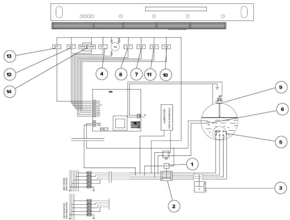
text_image
Electrical wiring diagram of an air conditioning system with numbered components and labeled connectionsFig. 37
LEGENDA / KEY
text_image
Electrical wiring diagram of an air conditioning system with numbered components and labeled connectionsFig. 38
LEGENDA / KEY
text_image
Electrical wiring diagram of an air conditioning system with numbered components and labeled connectionsLEGENDA / KEY
text_image
Electrical wiring diagram of a power supply or control module with numbered components and labeled connectionsFig. 40
LEGENDA / KEY
text_image
Technical schematic diagram of a fluid or gas processing system with numbered components and labeled partsFig. 41
LEGENDA / KEY
espresso coffee machines
Nuova Distribution Centre
LLC 6940Salashan PKWY BLDG A 98248
Ferdale, WA
Tel. +1.360.3662226
Fax +1.3603664015
videoconf.+1.360.3188595
espresso coffee machines
Via M. d'Antegiano, 6
62020 Belforte del Chienti
Macerata Italy
Tel. +39.0733.9501
Fax +39.0733-950242
espresso coffee machines
natural_image
Exterior view of a modern coffee machine with three side dishes and control knobs (no visible text or symbols)Aurelia®
MADE IN ITALY
MANUEL D'INSTRUCTIONS GEBRAUCHANWEISUNGEN
EC DECLARATION OF CONFORMITY


nuova simonelli
espresso coffee machines
Via M. D'Antegiano, 6 - 62031 Belforte del Chienti (MC)
declare under our responsibility that the product:
MACCHINE PER CAFFE' ESPRESSO
ESPRESSO COFFEE MACHINES
MODELS: Aurelia - versions Vip Plus, V, Esse.
to which this declaration relates, following the provisions of the Directives:
EN 60335-2-75:2004 + A1:2005 + A11:2006
in combination with
EN 60335-1:2002 + A1:2004 + A11:2004 + A12:2006 + A2:2006
EN 50366:2003 + A1:2006
following the provisions of the Directives
2006 / 95 / CE Low Voltage
2004 / 108 / CE (EMC)
data: Novembre 2008
November 2008
natural_image
Modern espresso machine with three side dishes and control knobs (no visible text or labels)
text_image
Aurelia® MADE IN ITALYCARACTERISTIQUES TECHNIQUES

text_image
Technical diagram of a coffee machine with labeled components A, B, and G, showing internal seating and control panel layout.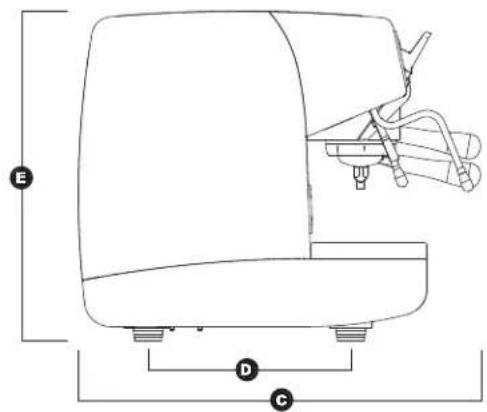
text_image
E D C| 2 Groupes 3 Groupes 4 Groupes | ||||||
| POIDS NET | 74 kg | 136 lb | 88kg | 194 lb | 104 kg | 229 lb |
| POIDS BRUT | 80kg | 176 lb | 98 kg | 216 lb | 120 kg | 264 lb |
| PUISS. THERMIQUE | 4500 W 4500 W 5000 W 5000 W 5000 W | |||||
| DIMENSIONS 780 mm | A | 14 " 1010 m | A 9 | A 516 " 1240 m | A 48 | A 516 " |
| B 635 mm | B 25" | B 865 mm | B 34" | B 1095 mm | B 43116 " | |
| C 540 mm 21 | C 18 " | C 540 mm | C 2118 " | C 540 mm | C 2118 " | |
| D 315 mm | D 12316 " 315 m | D 2 | D 316 " | D 315 mm 12 | D 316 " | |
| E 510 mm | E 20" | E 510 mm | E 20" | E 510 mm | E 20" | |
| F 135 mm | F 518 " | F 135 mm | F 518 " 135 mm | F 5 | F 18 " | |
| G 180 mm | G 7116 " | G 180 mm 7 | G 116 " 180 mm | G 7 | G 116 " | |

text_image
Aurelia® MADE IN ITALYINDICE
CARACTERISTIQUES TECHNIQUES ....2
- DESCRIPTION ....5
1.1 LISTE ACCESSOIRES 6
-
PRESCRIPTIONS DE SECURITE .....7
-
TRANSPORT ET DEPLACEMENT .....10
3.1 IDENTIFICATION MACHINE ....10
3.2 TRANSPORT 10
3.3 DEPLACEMENT 10
-
INSTALLATION ET OPERATIONS PRELIMINAIRES ....10
-
REGLAGES DU TECHNICIEN QUALIFIE 12
5.1 REMPLISSAGE MANUEL DE LA CHAUDIERE .....12
5.2 REGLAGE PRESSOSTAT POMPE .....12
5.3 REGLAGE ECONOMISEUR EAU CHAUDE .....13
5.4 REMPLACEMENT BATTERIE MONTRE (UNIQUEMENT SUR VERSION VIP PLUS) .....13
5.5 REMPLACEMENT DES TABLEAUX A POUSSOIRS .13
5.6 JOURNAL ELECTRONIQUE 13
- UTILISATION 14
6.1 MISE EN MARCHE DE LA MACHINE .....14
6.1.1 AURELIA VIP PLUS 14
6.1.2 AURELIA V/ESSE 15
6.1.3 AURELIA VIP-V/ESSE AVEC JOURNAL ELECTRONIQUE (OPTION) .....15
6.2 CONFIGURATION SELECTION .....16
6.3 PREPARATION DU CAFE 16
6.4 UTILISATION DE LA VAPEUR 16
6.5 PREPARATION DU CAPPUCCINO 17
6.6 SELECTION EAU CHAUDE 17
6.7 LANCE VAPEUR TEMPORISEE 17
- PROGRAMMATION 18
7.1 LEGENDE 18
7.2 PROGRAMMATION AURELIA VIP PLUS .....18
7.3 PROGRAMMATION AURELIA V 24
7.4 PROGRAMMATION AURELIA ESSE .....27
- NETTOYAGE ET ENTRETIEN .....28
8.1 ARRET DE LA MACHINE .....28
8.2 NETTOYAGE DE LA CARROSSERIE .....28
8.3 NETTOYAGE DES DOUCHES INOX .....28
8.4 NETTOYAGE DU GROUPE A L'AIDE DU FILTRE BORGNE ....28
8.5 NETTOYAGE DES FILTRES ET DES SUPPORTS A FILTRES ....28
8.6 REVIVIFICATION DES RESINES DE L'ADOUCISSEUR ....29
-
MESSAGES FONCTIONS MACHINE AURELIA PLUS ....30
-
MESSAGES FONCTIONS MACHINE AURELIA V....32
-
MESSAGES FONCTIONS MACHINE AURELIA S....33
INSTALLATION ELECTRIQUE AURELIA S .105
INSTALLATION ELECTRIQUE AURELIA PLUS Rel 3.xx ....106
INSTALLATION ELECTRIQUE AURELIA PLUS Rel 1.xx ....107
INSTALLATION ELECTRIQUE AURELIA V .108
INSTALLATION HYDRAULIQUE .....109

text_image
Aurelia® MADE IN ITALY1. DESCRIPTION Vip Plus V - Esse
text_image
1 2 3 4 5 6 7 8 9 10 20 11 1316 1214 19 18 17 15 Fig. 1LEGENDA
natural_image
Simple line drawing of a landscape with mountains, trees, and a cross symbol (no text or labels)
natural_image
Simple white electrical symbol on dark background, no text or numbers presentFig. 4

natural_image
Illustration of a hand using a coffee machine to adjust the tray (no text or symbols visible)
natural_image
Illustration of hands operating a washing machine with a black X symbol (no text or symbols present)
ATTENTION RISQUE DE BRULURES

3. TRANSPORT ET DEPLACEMENT
3.1 IDENTIFICATION DE LA MACHINE
RISQUE D'IMPACT OU D'ECRASEMENT
RISQUE D'IMPACT OU D'ECRASEMENT
natural_image
Illustration of a hand using a tool to clean or install a mechanical component, with no visible text or symbols.natural_image
Close-up of a mechanical component with labeled point A and Fig. 14 (no text or symbols beyond label)natural_image
Hand holding a tool with directional arrows indicating motion or flow (no text or symbols)natural_image
Close-up of mechanical components with no visible text or symbols, showing a circular motion indicator (no readable text or symbols)natural_image
Close-up of a mechanical device with labeled parts and tool tips, no readable text or symbols present.natural_image
Mechanical assembly diagram showing rotating components with no visible text or symbols5.6 JOURNAL ELECTRONIQUE
natural_image
Two metallic key-shaped components and a circular ring, labeled Fig. 20 (no text or symbols on the main objects)6.1 MISE EN MARCHE DE LA MACHINE
6.1.1 AURELIA VIP PLUS
MISE EN MARCHE / ARRET MANUEL
On - Off Automatique NON PROGRAMME
6.1.3 AURELIA VIP-V/ESSE AVEC JOURNAL ELECTRONIQUE (OPTION)
natural_image
Line drawing of a medical or laboratory device with five circular indicators and a central bowl, labeled Fig. 24 (no text or symbols on the device itself)LEGENDE TOUCHES
natural_image
Illustration of a hand using a magnifying glass to press a small object, labeled Fig. 25 (no text or symbols on the diagram itself)natural_image
Hand operating a device with control buttons and a numeric display (no text or symbols visible)natural_image
Line drawing of a hand using a espresso machine to press coffee into a cup (no text or symbols)6.6 SELECTION EAU CHAUDE
ATTENTION RISQUE DE BRULURES
natural_image
Three identical line drawings of washing machines with circular tops and a small human figure, labeled Fig. 29 (no text or symbols on devices)text_image
40 cc 60 cc 50 cc 85 cc 9 sec. 0 sec.natural_image
Close-up of a stainless steel coffee maker with five circular control buttons (no visible text or symbols)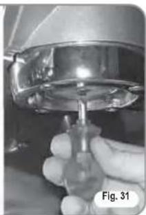
natural_image
Close-up of a hand holding a small transparent object, possibly a tool or component, with no visible text or symbols.natural_image
Modern espresso machine with three side dishes and control knobs (no visible text or labels)
text_image
Aurelia® MADE IN ITALYtext_image
Technical diagram of a coffee machine with labeled components and directional arrows indicating flow or movement.
text_image
E D C| 2 Gruppen 3 Gruppen 4 Gruppen | ||||||
| NETTOGEWICHT | 74 kg | 136 lb | 88kg | 194 lb | 104 kg | 229 lb |
| BRUTTOGEWICHT | 80kg | 176 lb | 98 kg | 216 lb | 120 kg | 264 lb |
| HEIZLEISTUNG | 4500 W | 4500 W | 5000 W | 5000 W | 5000 W | 5000 W |
| ABMESSUNGEN 780 m | A 30 | A 14 " 1010 m | A 9 | A 516 " 1240 m | A 48 | A 516 " |
| B 635 mm | B 25" | B 865 mm | B 34" | B 1095 mm | B 43116 " | |
| C 540 mm 21 | C 18 " 540 m | C 1 | C 18 " | C 540 mm 21 | C 18 " | |
| D 315 mm | D 12316 " 315 m | D 2 | D 316 " | D 315 mm 12 | D 316 " | |
| E 510 mm | E 20" | E 510 mm | E 20" | E 510 mm | E 20" | |
| F 135 mm | F 518 " | F 135 mm | F 518 " 135 mm | F 5 | F 18 " | |
| G 180 mm | G 7116 " | G 180 mm 7 | G 116 " 180 mm | G 7 | G 116 " | |

text_image
Aurelia® MADE IN ITALYINHALTSVERZEICHNIS
natural_image
Simple line drawing of a mountainous landscape with a cross symbol overlay (no text or symbols present)
natural_image
Illustration of hands operating a portable device with control panel and buttons (no text or symbols visible)
natural_image
Illustration of hands using a washing machine to adjust or clean a product (no text or symbols visible)
text_image
Technical diagram showing a mechanical assembly with labeled components and a hand holding a tool, accompanied by a schematic view.text_image
Technical diagram of a gas processing or distribution system with labeled components including equipment, tanks, and flow paths.LEGENDE
natural_image
Close-up of a mechanical assembly with rotating components and a circular motion arrow (no visible text or symbols)natural_image
Close-up of a mechanical device with multiple ports and wires, labeled A, showing no readable text or symbols.natural_image
Mechanical assembly diagram showing pipe connections and a circular motion arrow (no text or symbols)natural_image
Two metallic key holders and a circular ring on a plain surface (no text or symbols visible)natural_image
Diagram of a device with four circular indicators and a curved base, labeled Abb. 24 (no text or symbols on the diagram itself)TASTENERKLÄRUNG
natural_image
Illustration of a hand using a magnifying glass to press a small object, with no text or symbols present.natural_image
Hand inserting a button into a device panel (no text or symbols visible)natural_image
Illustration of a coffee maker using a pour-over machine with hands operating it (no text or symbols visible)natural_image
Three identical cartoon-style illustrations of a sunlight device with circular tops, connected by a line to a small figure (no text or symbols)natural_image
Close-up of a espresso machine lever with control buttons (no visible text or symbols)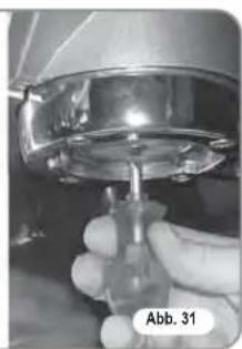
natural_image
Close-up of a hand holding a metallic mechanical component, labeled 'Abb. 31' (no other text or symbols visible)natural_image
Modern espresso machine with three side dishes and control buttons (no visible text or symbols)
text_image
Aurelia® MADE IN ITALYCARACTERÍSTICAS TÉCNICAS

text_image
Technical diagram of a coffee machine with labeled components A, B, and F indicating parts of the front panel.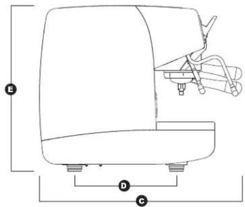
text_image
E D C| 2 Groupes 3 Groupes 4 Groupes | ||||||
| PESO NETO | 74 kg | 136 lb | 88kg | 194 lb | 104 kg | 229 lb |
| PESO BRUTO | 80kg | 176 lb | 98 kg | 216 lb | 120 kg | 264 lb |
| POT. TÉRMICA | 4500 W | 4500 W | 5000 W | 5000 W | 5000 W | 5000 W |
| MEDIDAS 780 mm 30 | A | 14" 1010 mm | A9 | 516" | A 1240 mm 48 | A 516" |
| B 635 mm | B 25" | B 865 mm | B 34" | B 1095 mm | B 43116" | |
| C 540 mm | C 2118" | C 540 mm | C 2118" 540 mm | C 21 | C 18" | |
| D 315 mm | D 12316" 315 mm | D | D 316" | D 315 mm 12 | D 316" | |
| E 510 mm | E 20" | E 510 mm | E 20" | E 510 mm | E 20" | |
| F 135 mm 5 | F 18" 135 mm | F 5 | F 18" | F 135 mm 5 | F 18" | |
| G 180 mm | G 7116" | G 180 mm 7 | G 116" | G 180 mm 7 | G 116" | |

text_image
Aurelia® MADE IN ITALYINDICE
CARACTERISTICAS TECNICAS .....72
- DESCRIPCIÓN .....75
1.1 LISTA DE ACCESORIOS....76
natural_image
Simple line drawing of a mountainous landscape with a cross symbol overlay (no text or symbols present)
natural_image
Simple electrical circuit symbol (no text or labels)Fig. 4

natural_image
Illustration of a hand using a coffee machine to adjust or install a tray (no text or symbols visible)
natural_image
Illustration of a hand using a tool to adjust or install a machine component, with no visible text or symbols.
natural_image
Diagram showing a hand cleaning a kitchen sink with a cylindrical device and a close-up of the component (no text or symbols present)text_image
Technical diagram of a gas or fluid system setup with labeled components and flow pathsLEYENDA
1 Endulzante
2 Filtro de red
3 Descarga ∅ 50 mm
natural_image
Close-up of a mechanical component with labeled point A and Fig. 14 (no readable text or symbols beyond label)natural_image
Hand holding a tool with directional arrows indicating motion or force (no text or symbols)natural_image
Close-up of mechanical components with no visible text or symbolsnatural_image
Close-up of a mechanical device with multiple ports and a labeled component (A), no readable text or symbols present.natural_image
Mechanical assembly diagram showing rotating components with directional arrows (no text or symbols)natural_image
Two metallic key-shaped tools with circular holes and a separate ring, labeled Fig. 20 (no text or symbols on the keys or ring)6.1 ENDIDO DE LA MÁQUINA
6.1.1 AURELIA VIP PLUS
natural_image
Line drawing of a medical or laboratory device with four circular indicators and a central dome (no text or symbols)LEYENDA BOTONES
natural_image
Illustration of a hand using a magnifying glass to press a small object, labeled Fig. 25 (no text or symbols on the diagram itself)natural_image
Hand operating a device with a knob and control panel (no visible text or symbols)natural_image
Line drawing of a person using a coffee machine to press coffee beans (no text or symbols)natural_image
Three identical illustrations of a washing machine with sun icons, shown from top to bottom (no text or symbols on the machines themselves)natural_image
Close-up of a stainless steel coffee maker with control buttons (no visible text or symbols)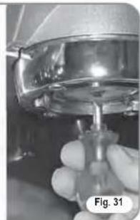
natural_image
Close-up of a hand holding a small mechanical component, possibly a valve or tool, with no visible text or symbols.text_image
Electrical wiring diagram of an air conditioning system with labeled components and connectionsFig. 37
LEGENDA/KEY
text_image
Electrical wiring diagram of an air conditioning system with numbered components and labeled connectionsFig. 38
LEGENDA/KEY
text_image
Electrical wiring diagram of an air conditioning system with labeled components and connectionsLEGENDA/KEY
text_image
Electrical wiring diagram of a refrigerant system with numbered components and labeled connectionsFig. 40
LEGENDA/KEY
espresso coffee machines
Nuova Distribution Centre
LLC 6940Salashan PKWY BLDG A 98248
Ferdale, WA
Tel. +1.360.3662226
Fax +1.3603664015
videoconf.+1.360.3188595
espresso coffee machines
Via M. d'Antegiano, 6
62020 Belforte del Chienti
Macerata Italy
Tel. +39.0733.9501
Fax +39.0733-950242