DigiMicro Profi - To scan dnt - Free user manual and instructions
Find the device manual for free DigiMicro Profi dnt in PDF.

User questions about DigiMicro Profi dnt
0 question about this device. Answer the ones you know or ask your own.
Ask a new question about this device
Download the instructions for your To scan in PDF format for free! Find your manual DigiMicro Profi - dnt and take your electronic device back in hand. On this page are published all the documents necessary for the use of your device. DigiMicro Profi by dnt.
USER MANUAL DigiMicro Profi dnt
natural_image
Digital microscope device with attached cable and USB connector (no visible text or symbols)Inhalt
Softwareinstallation....10
Software....10
Bildbearbeitung 12
natural_image
Technical line drawing of a microscope with an inset showing the base and top views (no text or symbols)natural_image
Technical line drawing of a microscope and its baseplate assembly (no text or symbols)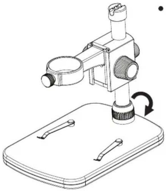
natural_image
Line drawing of a microscope mounted on a base with a rotating arrow indicating motion (no text or symbols)natural_image
Technical line drawings of three types of laboratory microscopes mounted on a base plate (no text or labels)natural_image
Diagram of a mechanical or electrical component with directional arrows indicating rotation and movement (no text or symbols)natural_image
Technical line drawing of a mechanical device with directional arrows indicating motion or movement (no text or symbols)natural_image
Technical line drawing of a mechanical device with a black arrow indicating a specific component (no text or symbols present)"No Device detected, please connect your Microscope directly to your USB Port."

Security instructions ....19
Appliance description
System requirements ....20
Delivery content 20
Appliance description ......21
Getting started 22
Software....26
Image editing 28
Specifications 30
Declaration of conformity 32
Disposal of electronic equipment ....32
Service informationen ....33
Warranty regulations 63
The company placing the product on the market
D-63128 Dietzenbach, Germany
Tel. +49 (0)6074 3714-0
Fax +49 (0)6074 3714-37
Service-Hotline +49 (0)6074 3714-31
Internet http://www.dnt.de
Email dnt@dnt.de
subject to change without prior notice

Please read this information carefully before you use the appliance.
General instructions
- Don't place the unit on unstable location, if it falls down, people may be injured.
- The unit is not a toy, please beware of small children.
- If you connect the unit to other electronic devices, please study also the security instruction of this device.
- If you have any question regarding the unit, how it works, the safety or the correct connection please contact our technical support or ask any specialist.
- The seller will not be liable for any damages caused by misuse of the product and any claim from third parties.
Environmental conditions
- Don't drop or shake the unit, it might be damaged.
- Avoid too high pressure to the LC-display, it might be damaged.
- Don't leave the unit where the temperature is higher than 60^ , e.g. in cars with closed windows in the summertime, near heaters or any other type of heat source.
- Don't use the unit in rooms with high humidity e.g. bathrooms. Parts of the apparatus, tube and mini camera, are water proofed See technical specifications for details
- Don't use the unit at dusty places.
Technical problems
- In case any foreign material or liquid gets into the product, please immediately remove the power cord. Before you use it again, ask your authorised dealer to check the product carefully.
- Please do not hesitate to contact our service center.
Packaging material
- Please don't keep any packaging material within reach of small children. It can become a dangerous toy.
Maintenance
- We strongly suggest using a clean, dry, non-alcohol cotton swab to clean the glass surface periodically to produce a clear image during operation.
Systemrequirements
- OS: MS Windows XP SP2/Vista/ Windows7/Windows8
- min. Prozessor Pentium4 1800 or compatible AMD Processor
- RAM 512 MB
• 24 Bit Video card, 64M - USB 2.0 port
- CD-ROM drive
Delivery content
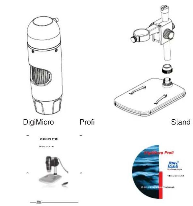
user manual CD
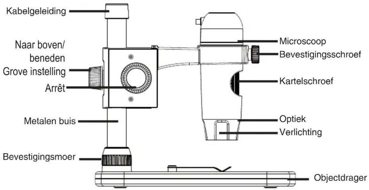
Appliance description left side

text_image
cable guide up/down rough adjustment lock/release metal pole mounting nut mikroscope mounting screw focus adjustment optic illumination carriage stageEnglish
right side
text_image
microscope slide up/down rough focusUSB cable

text_image
snapshot button(Windows only) LED dimmer USB connectorGetting started
Getting started
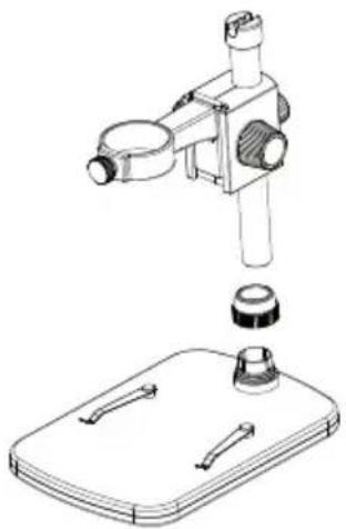
Stand mounting.
- Slide the mounting nut on the metal pole.

natural_image
Technical line drawing of a microscope with an inset showing the base and top view (no text or symbols)- Put the metall pole into the female part of the stage.

natural_image
Technical line drawing of a mechanical device with a base plate and a downward arrow indicating motion (no text or symbols)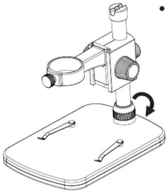
natural_image
Line drawing of a microscope mounted on a base with a rotating arrow indicating rotation (no text or symbols)- Fix the Pole on the stage.

natural_image
Technical line drawings of a microscope with three views (top, front, side) showing different mechanical components and mounting base (no text or labels)- Put the microscope into the ring of the stand.
Getting started
Getting started
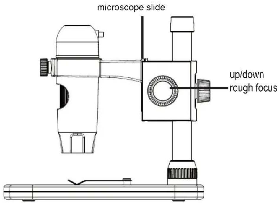
The microscope is attached to a metal pole and adjusted with different wheels.
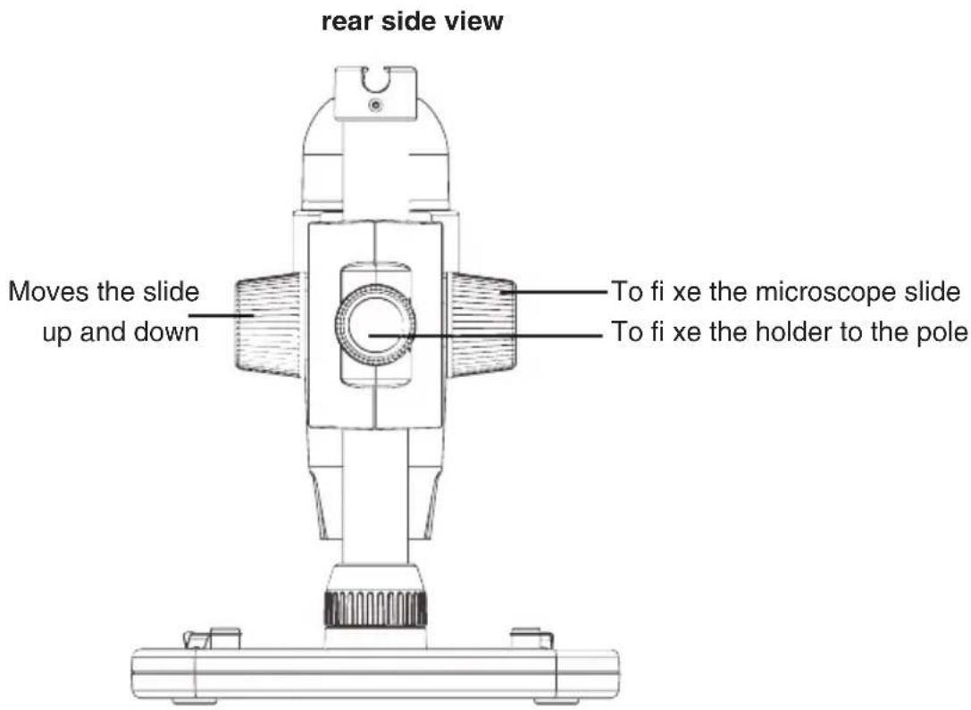
text_image
rear side view Moves the slide up and down To fi xe the microscope slide To fi xe the holder to the pole
natural_image
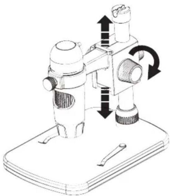
Diagram of a mechanical or electrical component with directional arrows indicating rotation and movement (no text or symbols)- Rotate the wheel on the rear side for a rough adjustment. Loosen the wheel and mount the holder to an appropriate height.
natural_image
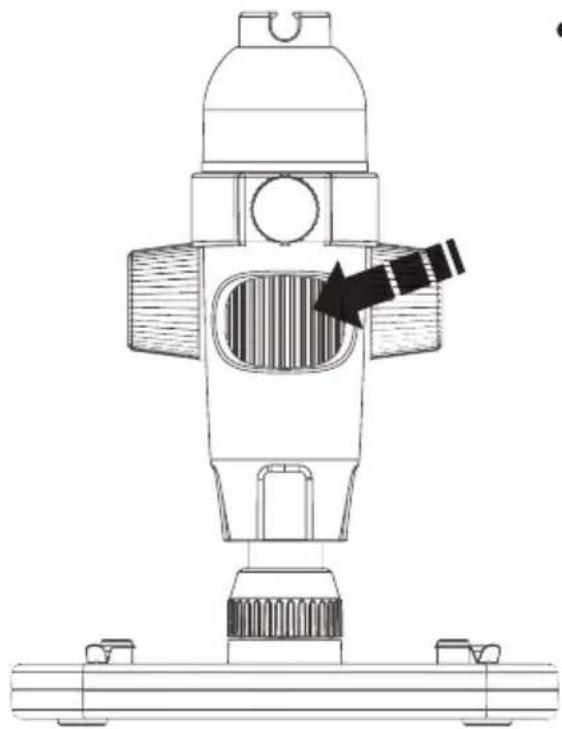
Technical line drawing of a mechanical device with directional arrows indicating motion or force (no text or symbols)- Move the slide to an appropriate height. Rotate the wheel to get a rough focus.
natural_image
Technical line drawing of a mechanical device with a central component and base mount (no text or symbols)- Rotate the wheel to get a fine focus.
Software installation
Install the software
- Insert the driver CD into CD-ROM Drive and this will automatically display the following interface.
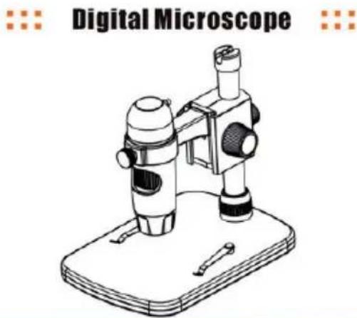
natural_image
Illustration of a digital microscope device on a base (no text or symbols on the device itself)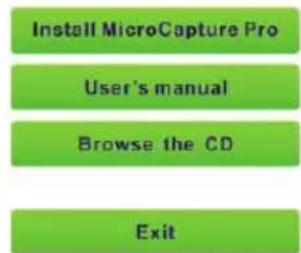
text_image
Install MicroCapture Pro User's manual Browse the CD Exit
chemical
Molecular structure diagram showing orange, blue, and black spheres representing atoms in a chain- Install MicroCapture Pro. Click Install MicroCapture Pro and the installation wizard will guide you through the whole process.
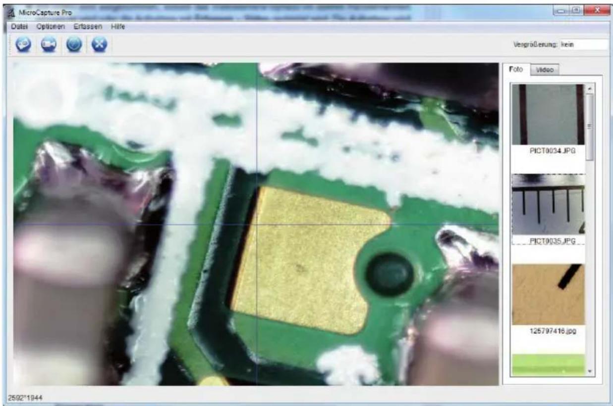
Full user's manual can be viewed by clicking User's Manual. - Connect your Microscope to your PC USB port, start the software by clicking the Microcapture Pro icon generated on the desktop after installation and you will see the following screen pop up.
- When the Microscope is disconnected from your PC USB port, the following message will pop up: No Device detected, please connect your Microscope directly to your PC USB port.
Software microcapture Pro
- The software ha a multilanguage user interface. To change the language select Options > Language > English.
- The captured image is displayed on the right side as a thumbnail.
- If the mouse moves over a thumbnail, the image is shown in the preview window.
- The right mouse button shows a submenu where you can open, save, copy and delete the photo. Open will open the photo in the preview window. Save or Save as will open a dialog window to browse a folder of your choice. Copy will copy the photo to the clipboard. Delete to delete the current photo. Delete all to delete all photos from the list.

The transmission rate of the USB interface is limited. Therefore, the resolution in the preview is limited to 1280x960, but are photos are stored in the preview size.
- To take a phot press snapshot button or the camera icon above the preview window. The photos are stored the Photos Directory.
- The captured image is displayed on the right side as a thumbnail.
- To capture a video click on the video camera button above the preview window or select Capture > Video in the menu. Videos are stored in the Video Directory. To stop the capturing click on the flashing video camera button. The video is stored in the AVI format.
Main menu
File
Photos Directory: Folder to store the photos.
Video Directory: Folder to store the photos.
Exit: Exit the program.
Options
Preview Size You can change the preview size. The size of the photo taken is equivalent to the preview size selected in the Options menu/Preview Size.
Date/Time On/Off displays the date and time in the photo or video.
Language: Setup the language of the user interface
Fullscreen mode: You can enter & quit full screen mode by:
- Double-clicking the preview area.
- Clicking the full screen icon.
Crossing On/Off displays a cross in the preview windo.
Capture
Photo: Captures a single photo
Video: Starts & stops capturing a video.
Software
Image editing
text_image
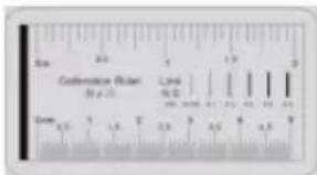
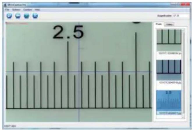
Centedron Ruler (0.5 x 2) Derm 1.5 2.5 3.5 4.5 5.5Focus microscope on the attached calibration ruler and then adjust the mangnifi cation till the picture is clear. Take a picture for the selected area when the dial is parallel to the crossing as below.
bar
| Value | |-------| | 2.5 |Double-click on the picture to enter into measurement interface as below.
Click Calibration icon, and then move mouse to the picture. Click on the beginning and ending points across a known value. Now a dialog will popup as below and you need to enter the exact value of the measurement sample into 'Actual dimension'.

text_image
Adjust magnitude Default Adjusted sensitivity Adjusted magnitude: 37.0 Use adjusted map, or measure map.Then the software will automatically calibrate the magnifi cation rate. Click 'OK' and the adjusted magnifi cation rate will show in the upper right corner.
Menu bar

natural_image
Row of blue circular icons with icons representing file, folder, image, and refresh symbols (no text or labels)store image
copy image to clipboard
copy image
last image, next image
undo, redo

text_image
Line Arrow Freehand Rectangle Line PropertiesDrawing

- Click icon to choose any kinds of drawing under the pull-down manual as below.
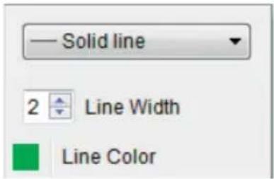
text_image
Solid line 2 Line Width Line Color- properties of the line

text_image
T Choose Font Text Color
- Click icon and set the font for the text in the popup dialogue

text_image
Any Angle Line Continuous Line Radius Circle Diameter Circle Three Points Angle Line Properties Text Properties Set Units- Double-click on the picture to enter into measurement interface. Under the 'Measurement' icon, you can choose any desired options to measure.
- Any Angle Line Measurement. Simply click from one point and drag to the next point, and then release the click.
- Continuous Line Measurement. The Continuous Line measurement allows you to measure any continuous desired length. Simply click and drag from one point to other desired points, and then release the click.
- Radius Circle Measurement. Simply click and extend out to the desired radius, the radius, circumference and area of the circle will show up accordingly.
- Diameter Circle Measurement. Simply click and extend out to the desired diameter, the diameter, circumference and area of the circle will show up accordingly.
- Three Points Angle Measurement. Simply defi ne any three points angle and click, the angle value will then display.
Specifications
Specifications
Image sensor 5 Mega Pixels
Video resolution 2592x1944, 2048x1536, 1600x1200), 1280x960 Pixel
Still capture resolution 2592x1944, 2048x1536, 1600x1200), 1280x960 Pixel
Colour 24-Bit-RGB
Focus Range manual focus from 10mm to 300mm
Magnification Ratio ca. 20x, 200x and 300x
Imgae format JPG
Video format AVI
White balance automatic
Light source 8 LED, white
PC Interface USB 2.0
OS Windows XP SP2/Vista, Windows 7, Windows8, MAC OS 10.6 or higher
DC Power 5 V (USB port)
Microscope 110x35mm
Stand 175x140x110mm
Declaration of Conformity
Hereby, dnt GmbH, declares that this DigiMicro Profi is in compliance with the essential requirements and other relevant provisions of Directive 1999/5/EC.
The declaration of conformity is available for download www.dnt.de/konformitaet
Disposal of electrical and electronic equipment

This symbol on the product or in the instructions means that your electrical and electronic equipment should be disposed at the end of its life separately from your household waste. There are separate collection systems for recycling in the EU. For more information, please contact the local authority or your retailer where you purchased the product.
Service information
In case of complaints your device shows a defect, please consult your dealer or contact the service department of dnt to agree a servicing.
Service time: Monday until Thursday from 8.00-17.00h
Friday from 8.00-16.00h
Hotline/Service: 06074 3714 31
E-Mail: support@dnt.de
Please do not send your device to our address without request by our service team. The expense and the risk of the loss are for debits of the sender. We reserve to refuse the unrequested shipment or return corresponding goods to the sender at buyer's risk and expense.
Contenu
text_image
DigiMicro Profi John's Pathway
text_image
Digital Micro Profi dnt® Digital Micro Products © digital product Trademarknatural_image
Technical line drawing of a mechanical device with a base and top component, showing internal components and an upward arrow (no text or symbols)natural_image
Technical line drawing of a mechanical device with a base plate and a downward arrow indicating motion (no text or symbols)
natural_image
Line drawing of a microscope mounted on a tray with a rotating base (no text or symbols)natural_image
Technical line drawing of a microscope with three views (top, front, side) showing different mechanical components and mounting base (no text or labels)natural_image
Diagram of a mechanical or electrical component with directional arrows indicating rotation and movement (no text or symbols)natural_image
Technical line drawing of a mechanical device with directional arrows indicating motion or movement (no text or symbols)natural_image
Technical line drawing of a mechanical device with a black arrow indicating a specific component (no text or symbols present)natural_image
Three blue circular icons with white document, folder, and monitor symbols (no text or labels)Enregistrer l'image
Annuler (undo), refaire (redo)

Pied de support 175x140x110mm
natural_image
Line drawing of a cylindrical device with a lid and internal grating (no text or symbols)DigiMicro
Profi
natural_image
Technical line drawing of a mechanical device with three components, no text or symbols presentStandvoet

text_image
DigilMicro Profi Dikraqakinytext_image
Hydshiro Profi DNT® https://www.rpt.org © or a long-lived TrademarkApparaataanzicht
van links
natural_image
Technical illustration of a mechanical device with a base and top component, showing assembly steps (no text or symbols)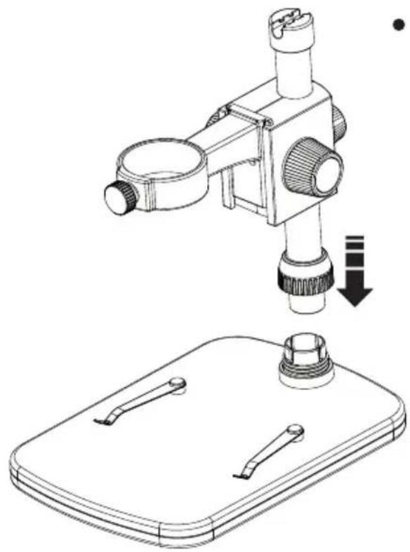
natural_image
Technical line drawing of a microscope and its base plate assembly (no text or symbols)natural_image
Line drawing of a microscope mounted on a base with a rotating arrow indicating rotation (no text or symbols)natural_image
Technical line drawing of a microscope with three views (top, front, side) showing different mechanical components and mounting base (no text or labels)natural_image
Diagram of a mechanical or electrical component with directional arrows indicating rotation and movement (no text or symbols)natural_image
Technical line drawing of a mechanical device with directional arrows indicating motion or force (no text or symbols)natural_image
Technical line drawing of a mechanical device with a highlighted internal component and base mount (no text or symbols)"No Device detected, please connect your Microscope directly to your USB Port."

text_image
Unsampling error: 37.21 Description: Model distance Composite simulation: 37.21 ■ Version composite simulation and simulation testing OKnatural_image
Three blue circular icons: a floppy disk, a document, and a computer monitor (no text or symbols)Beeld opslaan
Warranty regulations
- In general the European warranty regulations are valid. Warranty starts with receipt of unit. In a warranty case, please submit the unit together with invoice, unit pass and error description. Without these documentary evidence we are not obliged to a warranty performance.
- During warranty period we repair all constructional or material defects which are caused by a manufacturing fault. It is in the decision of the manufacturer to change or replace defective parts/units. Further claims are excluded. Changed parts will automatically go over into our property. We will not be held responsible for future damages.
- Manipulation on the unit through non-authorized companies/persons automatically leads to an end of warranty period.
- Excluded of warranty claims are damages due to improper treatment, not following the manual, oxidation of batteries, permanent usage.
- The initial warranty period is not extended because of repair or replacement of parts.
- These warranty regulations are valid in the Federal Republik of Germany.