Alpha 25ES - Speaker INFINITY - Free user manual and instructions
Find the device manual for free Alpha 25ES INFINITY in PDF.

User questions about Alpha 25ES INFINITY
0 question about this device. Answer the ones you know or ask your own.
Ask a new question about this device
Download the instructions for your Speaker in PDF format for free! Find your manual Alpha 25ES - INFINITY and take your electronic device back in hand. On this page are published all the documents necessary for the use of your device. Alpha 25ES by INFINITY.
USER MANUAL Alpha 25ES INFINITY
natural_image
Black box-shaped electronic speaker with two circular speakers and a central hub (no visible text or symbols)Infinity Alpha™ Series
The Infinity Alpha Series of loudspeakers continues Infinity's long-standing commitment to accurate sound reproduction. Our patented Ceramic Metal Matrix Diaphragm™ (C.M.M.D.™) drivers, precision dividing networks and rigid, heavily braced enclosures combine to deliver uncompromised performance in any stereo or multichannel home theater system. The Infinity Alpha 25ES is the perfect loudspeaker to complete any home theater system.
Unpacking the Speaker
If you suspect damage from transit, report it immediately to your dealer. Keep the shipping carton and packing materials for future use.
Choosing Proper Placement and Setup
The Infinity Alpha 25Es surround speaker can be used in side or rear channel applications. Please refer to the placement and setup method for your application. The first step is to determine the application for which your Infinity Alpha 25Es surround speaker will be used.
If you are using the Infinity Alpha 25Es for surround channels in a 5-channel home theater system or for side channels in a 6- or 7-channel home theater system (Application 1), please follow the directions below.
If you are using the Infinity Alpha 25ES as a rear speaker in a 6- or 7-channel home theater system (Application 2), please follow the directions on page 3.
Placement (Application 1)
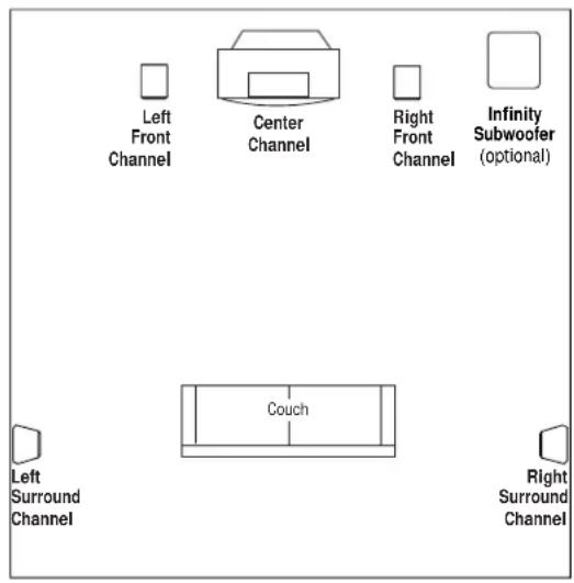
When using the Infinity Alpha 25es for surround channels in a 5-channel home theater system or for side channels in a 6- or 7-channel home theater system, refer to Figures 1 and 2. The speakers should be placed perpendicular to or slightly behind the primary listening location, as shown.
FIGURE 1 – T his overhead view shows a typical home theater plan.
text_image
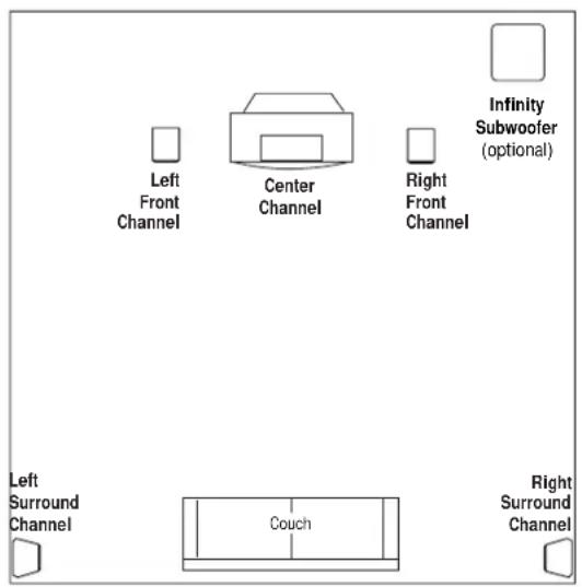
Left Front Channel Center Channel Right Front Channel Infinity Subwoofer (optional) Couch Left Surround Channel Right Surround ChannelFIGURE 2
text_image
Left Front Channel Center Channel Right Front Channel Infinity Subwoofer (optional) Left Surround Channel Couch Right Surround ChannelSetting the Surround Configuration Selector
It is generally recommended that the selectable surround mode configuration be set to Bipole. This will provide a large ambient surround sound field while allowing for precise localization of sound effects that the filmmaker has placed in the surround tracks.
If the side walls on which the speaker will be mounted are more than about 14' from the listening position, setting the Surround Mode Configuration Switch to Monopole may offer improved performance. It is also recommended that the Monopole position be selected if the speakers will be mounted close to a corner, as shown in Figure 2.
If you are using a receiver/processor with a THX ^ surround mode and have selected the THX surround mode, it may be beneficial to use the Dipole setting. This is a matter of personal preference and may change depending on the individual film soundtrack. It is also recommended that the Dipole setting be used with older recordings that are only recorded with a Dolby* Pro Logic* (not the newer Dolby Digital) soundtrack.
IMPORTANT NOTE: The set of drivers that the arrow in Figure 3 points to should be installed toward the front of the room. It does not matter whether or not the tweeter is positioned above or below the woofer.
This will ensure proper operation and performance should the Monopole or Dipole position on the surround mode configuration switch be selected.
FIGURE 3 – Surround mode configuration switch.

text_image
BIPOLEDIPOLE MONOPOLEPlacement (Application 2)
When using the Infinity Alpha 25es as a rear speaker in a 6- or 7-channel home theater system, refer to Figures 4 and 5. The speaker(s) should be mounted on the rear wall facing the listening area, between the side channel speakers. If you are using one rear speaker, it should be mounted as close as possible to the center of the listening area. When using two rear speakers, they should be spaced evenly within the width of the listening area.
Setting the Surround Configuration Selector
When used as a rear channel speaker in a 6- or 7-channel system, it is recommended that the Surround Mode Configuration Switch be set to Bipole, as shown in Figure 6.
FIGURE 4 – T his overhead view shows a typical home theater plan with a single rear-center surround channel.

text_image
Left Front Channel Center Channel Right Front Channel Infinity Subwoofer (optional) Couch Left Side Channel Right Side Channel Rear Center ChannelFIGURE 5 – T his overhead view shows a typical home theater plan when using two rear-channel speakers.

text_image
Left Front Channel Center Channel Right Front Channel Infinity Subwoofer (optional) Couch Left Side Channel Right Side Channel Left Rear Channel Right Rear ChannelFIGURE 6 – Surround mode configuration switch.

text_image
BIPOLEDIPOLE MONOPOLEWALL-MOUNTING
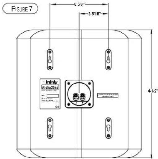
The Infinity Alpha 25es speaker is designed to mount directly to a wall. Each speaker has (4) keyholes in the rear to allow either left- or right-side placement. Each speaker will require (2) 1-1/2," #8 wood screws fastened to a wall stud. If a wall stud is unavailable, install an anchor appropriate for a 1-1/2," #8 screw. Use the supplied template to accurately position the screws on the wall and refer to the diagrams for more assistance.
NOTE: The customer is responsible for the correct selection and use of mounting hardware (available through hardware stores) that will ensure the proper and safe wall-mounting of the speakers.
Step 1. Position the supplied wall-mount template on the wall in the desired speaker location. Make two markings per speaker.
text_image
FIGURE 7 6-5/8" 3-5/16" Infinity Alpha25es 14-1/2"Step 2. Fasten (2) 1-1/2, " #8 wood screws to the wall using the markings placed in Step 1 as your guide. Leave a 3/16" space between the wall and screwhead. If a wall stud is not available, use an appropriate anchor.
Step 3. Attach speaker wire, as shown on page 5.
Step 4. Place the speaker on the wall by aligning the upper two keyholes on the back of the speaker to the screwheads on the wall. Once positioned properly, the speaker should slide down slightly and become secure.
IMPORTANT NOTE: The set of drivers that the arrow in Figure 3 points to should be installed toward the front of the room. It does not matter whether or not the tweeter is positioned above or below the woofer.
This will ensure proper operation and performance should the Monopole or Dipole position on the surround mode configuration switch be selected.
WIRING THE SYSTEM
IMPORTANT: Make sure all equipment is turned off before making any connections.
For speaker connections, use a minimum #16-gauge speaker wire with polarity coding. The side of the wire with a ridge or other coding is usually considered positive polarity (i.e., +). Heavier-gauge wire should be used when more than 50 feet of speaker wire is required. The wire channels on the rear of the Infinity Alpha 25Es will accommodate most types of 14- to 18-gauge wire.
NOTE: If desired, consult your local Infinity dealer about speaker wire and connection options.
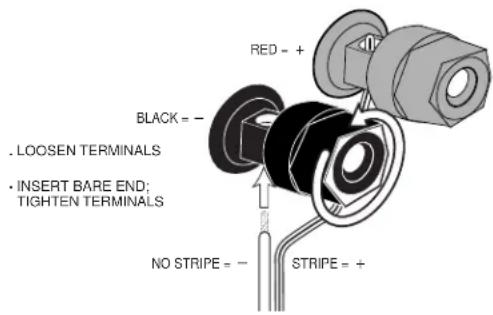
The speakers have coded terminals that accept a variety of wire connectors. The most common connection is shown in Figure 8.
To ensure proper polarity, connect each + terminal on the back of the amplifier or receiver to the respective + (red) terminal on each speaker, as shown in Figure 9. Connect the—(black) terminals in a similar way. See the owner's guides that were included with your amplifier or receiver to confirm connection procedures.
IMPORTANT: Do not reverse polarities (i.e., + to - or - to +) when making connections. Doing so will cause poor imaging and diminished bass response.
text_image
RED = + BLACK = - . LOOSEN TERMINALS . INSERT BARE END: TIGHTEN TERMINALS NO STRIPE = - STRIPE = +FIGURE 8 – This example shows how to connect bare wires to the terminals. Banana plugs may also be inserted directly into the rear of the connector.
NOTE: Banana plugs will protrude past the speaker enclosure, requiring a small cutout in the wall behind the speaker. Speaker wire may be run through this hole as well.

text_image
(one channel shown) Receiver or Amplifier (rear view) + - BLACK RED - + Speaker (rear view)FIGURE 9 – Wiring diagram shows polarity connections for one channel.
FINAL ADJUSTMENTS
Check the speakers for playback first by setting the system volume control to a minimum level, and then by applying power to your audio system. Play a favorite music or video segment and increase the system volume control to a comfortable level.
NOTE: You should hear balanced audio reproduction across the entire frequency spectrum. If not, check all wiring connections or consult the authorized Infinity dealer from whom you purchased the system for more help.
When the Infinity Alpha 25Es speakers are used as part of a Dolby Digital or DTS® multichannel home theater system with a powered subwoofer, it is recommended that you set your receiver/processor speaker mode to “small” or “high-pass” for all channels connected to an Infinity Alpha 25Es. In addition, some receivers/processors allow you to adjust the high-pass frequency for the “small” or “high-pass” setting. If your receiver/processor has this capability, it is recommended that you set the high-pass frequency to the lowest setting above 70Hz. Consult your receiver/processor manual for more information about these adjustments.
The placement and setup instructions in this manual are written in general terms to cover most typical installations. We realize that each room is different and that your specific installation may require some modification to these guidelines. You can be sure that if you need to install the speakers outside the guidelines in the manual, they will still deliver excellent sound with any music or film soundtrack.
Feel free to experiment with the Surround Mode Selector Switch to determine the best settings in your room with your system.
The Infinity Alpha 25Es does not require any routine maintenance. When needed, use a soft cloth, dampened with water only, to remove any fingerprints or dust. Clean the grille by gently vacuuming.
NOTE: Do not use any cleaning products or polishes on the cabinet or grille.
SPECIFICATIONS
Infinity Alpha 25ES
Frequency Range ( ± 3dB)
60Hz - 22kHz
Recommended 10 – 125 watts
Amplifier Power Range
Sensitivity
87dB
(2.83V @ 1 meter)
Nominal Impedance
8 ohms
Crossover Frequency 2,500Hz; 24dB/octave
Low-Frequency Drivers Dual 5-1/4" (133mm)
High-Frequency Driver(s) Dual 1" (25mm) C.M.M.D.
Dimensions H 14-1/2" (368mm)
W 14-1/8" (359mm)
D 7" (178mm)
Weight
18 lb (8.2kg)
Grille
Black cloth
(white cloth on white model)
Infinity continually strives to update and improve existing products, as well as create new ones. The specifications and construction details in this and related Infinity publications are therefore subject to change without notice.
Declaration of Conformity

We, Harman Consumer International
2, route de Tours
72500 Chateau-du-Loir
France
declare in own responsibility, that the product described in this owner's manual is in compliance with technical standards:
EN 50081-1:1992
EN 50082-1:1992

Robin Marshall
Harman Consumer International
Chateau-du-Loir, France. 9/02

Infinity
H A Harman International Company
© 2002 Harman International Industries, Incorporated.
250 Crossways Park Drive, Woodbury, NY 11797 USA 800.553.3332 (USA Only)
www.infinitysystems.com
Infinity is a registered trademark, and Ceramic Metal Matrix Diaphragm (C.M.M.D.) is a trademark, of Harman International Industries, Incorporated.
*Trademarks of Dolby Laboratories.DTS is a registered trademark of Digital Theater Systems,Inc.
Ceramic Metal Matrix Diaphragm (C.M.M.D.) patent nos. 6,327,372 and 6,404,897.
Printed in USA 9/02 Part No.335833-001