9.35 - Radiator DELONGHI - Free user manual and instructions
Find the device manual for free 9.35 DELONGHI in PDF.
Download the instructions for your Radiator in PDF format for free! Find your manual 9.35 - DELONGHI and take your electronic device back in hand. On this page are published all the documents necessary for the use of your device. 9.35 by DELONGHI.
USER MANUAL 9.35 DELONGHI
A) If your appliance comes fitted with a plug, it will incorporate a 13 Amp fuse. If it does not fit your socket, the plug should be cut off from the mains lead, and an appropriate plug fitted, as below.
WARNING: Very carefully dispose of the cut off plug after removing the fuse: do not insert in a 13 Amp socket elsewhere in the house as this could cause a shock hazard.
With alternative plugs not incorporating a fuse, the circuit must be protected by a 15 Amp fuse.
WARNING - THIS APPLIANCE MUST BE EARTHED IMPORTANT
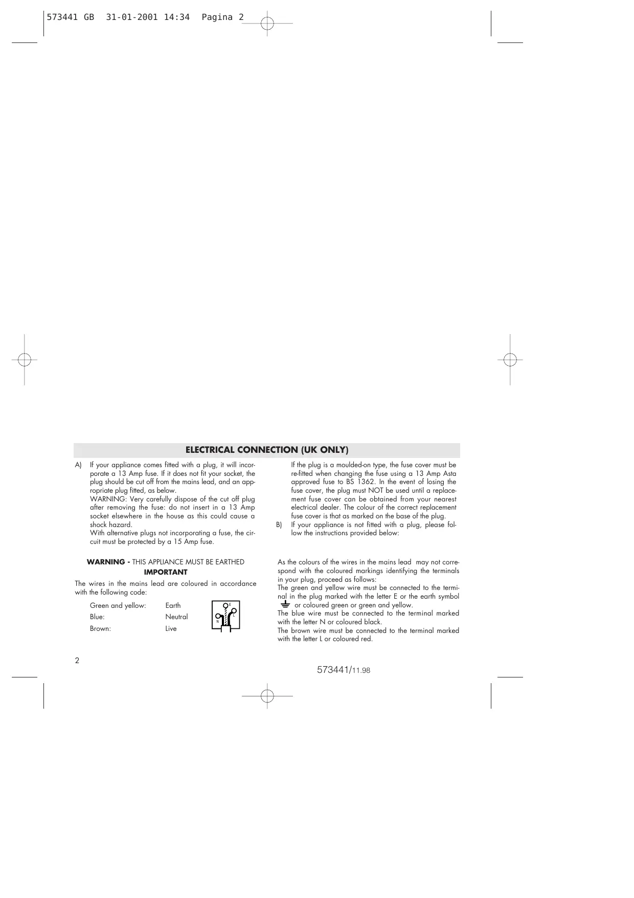
The wires in the mains lead are coloured in accordance with the following code:
Green and yellow:
Blue:
Brown:
Earth
Neutral
Live

If the plug is a moulded-on type, the fuse cover must be re-fitted when changing the fuse using a 13 Amp Asta approved fuse to BS 1362. In the event of losing the fuse cover, the plug must NOT be used until a replacement fuse cover can be obtained from your nearest electrical dealer. The colour of the correct replacement fuse cover is that as marked on the base of the plug.
B) If your appliance is not fitted with a plug, please follow the instructions provided below:
As the colours of the wires in the mains lead may not correspond with the coloured markings identifying the terminals in your plug, proceed as follows:
The green and yellow wire must be connected to the terminal in the plug marked with the letter E or the earth symbol 一2 or coloured green or green and yellow.
The blue wire must be connected to the terminal marked with the letter N or coloured black.
The brown wire must be connected to the terminal marked with the letter L or coloured red.
CATALYTIC HEATER
Technical Data
| Type | Category | Maximum Input | Medium Input | Low Input | Gas pressure |
| see rating label | KW g/h | KW g/h | KW g/h | ||
| 3.0 218 | 2.35 170 | 1.85 134 | 28÷30 mbar | ||
This appliance is designed to operate with Butane, propane or mix LPG at nominal pressure: 28 ÷ 30 mbar. For a correct gas combustion the required air quantity is 6m^3/h .
WARNING
- ALWAYS use heater in accordance with instructions. Read the instructions book carefully and keep it in a safe place.
- This appliance requires a rubber tube and a pressure regulator in accordance with the law in force. If not supplied check with your gas supplier.
- Use ONLY in a well ventilated area.
- This appliance MUST NOT be used in basements, high rise flats, bathrooms or bedrooms and in rooms having volume less than 18,5m^3 (37 m³ in living rooms).
- This appliance emits the combustion residues in the room in which is used.
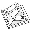
- DO NOT place clothes or other materials on the heater, as apart from the danger of fire their presence could affect the efficient working of the appliance (fig. 1).
-
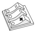
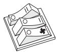
DO NOT move heater from room to room when it is lit (fig. 2).
-
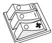
DO NOT position heater alongside a wall or near curtains or arm-chairs etc. (fig. 3 - 4).
- ALWAYS face heater towards centre of room. Special care should be taken if the heater is on a surface where it can move or twist on its wheels or castors if knocked by a child or dog, etc.
- Minimum Clearance : 200 mm from sides,1500 mm from front.
- Be sure installation is complying to local standard.
- Set the appliance to run on maximum for at least 15 minutes the first time it is used, in order to get rid of the "new" smell and a small amount of smoke coming from protective substances applied to the components. Air the room while this procedure takes place.
Safety device
The heater you have purchased is fitted with safety devices which come on in the event of malfunctioning while the appliance is in use. If the pilot light (placed opposite the burner) accidentally goes out, or if the room is not sufficiently ventilated, the safety device will block the gas flow, causing the heater to go off.
Gas leakages
If a leak is suspected, turn off gas at the gas bottle, open the window and air the room. DO NOT disconnect the pressure regulator. Extinguish all naked lights. Slowly turn the gas on and brush the connections with soapy water or liquid detergent - a gas leak will form bub
bles. If a leak is found, turn the gas off and inform your Dealer. DO NOT use the heater again until it has been inspected by your Dealer.
NEVER USE MATCHES TO FIND LEAKS.
GENERAL SAFETY INSTRUCTIONS
Gas bottle
Gas Bottle with 15kg of maximum capacity can be installed.
Changing of gas bottle must not be carried out in the presence of a naked flame.
Use the gas bottle always in upright position. If a screw on regulator is used ensure that the regulator washer is present and in good condition -replace if in any doubt.
To place the bottle in position, remove the rear panel which faces the inside during transport, by unfastening the screws; than put the bottle in position and replace the panel.
Do not turn the bottle upside down to use completely its content.
Pressure regulators, rubber tubes and clips
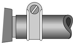
fig. 5
| Control knob setting | Room Size | Room Aperture |
| 1) Position ♂big flame (maximum rate) | 30 m3 | 75 cm2 |
| 2) Position ♂medium flame (medium rate) | 23.5 m3 | |
| 3) Position ♂small flame (low rate) | 18.5 m3 |
CHECK that tubing is completely over the nozzles at each end of the tubing and that it is held firmly in place by tube clips (See fig.5). Examine flexible tubing regularly and get your Dealer to fit new tubing 400mm long complying to local standard, if perished, worn
or damaged. In any case replace the tube every 5 years.
When connecting the pressure regulator to the gas bottle avoid undue twisting of the flexible tubing.
A 28 ÷ 30 mbar (11.2 in w.g.) pressure regulator for Butane or Propane complying to local standard must be connected to the appliance with the above tubing, using suitable tube clips.
Ventilation
USE ONLY IN A WELL VENTILATED ROOM
Adequate ventilation must be provided in rooms in which the heater is used. This ensures removal of the products of combustion and allows the entry of replacement air.
The following table shows the smallest size of room suitable for each heat setting and the dimensions of the aperture which must be provided equally divided between high and low level, according with the maximum, medium or minimum power.
Safety guard
The guard is to prevent risk of fire and no part of it should be permanently removed.
It does not give full protection for young children or the infirm.
OPERATING INSTRUCTIONS
Lighting the heater
- Turn on the gas at the gas bottle tap.
- FROM « ● » POSITION, fully depress the control knob for 15 seconds and turn to (Big Flame) position. (If pilot flame does not ignite return to starting position and repeat). Continue to fully depress the knob for a further 20 seconds to allow the thermocouple probe to heat up. Leave control knob in position (big flame) for 10 minutes then turn the knob to select the desired setting as follows:
(Big Flame) Maximum Input,
(Small Flame) Low Input
(Medium Flame) Medium Input,
Auxiliary ignition
Should piezoelectric starter fail to work, repeat operation on control knob and use a match to light pilot flame.
Tunring off the heater
Turn off the gas bottle tap.
The Heater will be totally "OFF" only if the tap at the gas bottle is turned off.
OFF
Ventilation +900W heating
(It can be used together with the 3000 W gas burners - for the very fast heating of the room).
Ventilation only
(It can be used together with the gas burners for an adequate heat distribution).
Ventilation +1800W heating
(It can be used together with the gas burners - 3100 W - for the fast heating of the room).
Important
When the operating knob is left at the end of the starting time (see rating plate and instruction manual), this must move up about 5mm and return to its starting height. If this does not happen, shut the gas valve and contact your aftersales service centre. Do noy let the item work with the operating knob pressed downwards by force.
VENTILATED CATALYTIC HEATER
Electrical connection
- Before using the appliance check that your supply voltage is the same as that shown on the rating label of the unit.
- Connect your heater to earth provided socket only, having a capacity of at least 10/16 A.
- THIS APPLIANCE COMPLIES WITH THE EEC DIRECTIVE 89/336, relating to electromagnetic compatibility.
OPERATION AND USE
Fully insert plug into socket-outlet and switch on the fan heater following the instructions below.
Before switching on the gas burner, read carefully the relevant operating instructions.
IMPORTANT
DO NOT cover the appliance when in operation, this could cause a dangerous rise of the temperature of the fan heater with consequent risk of fire.
Important notes
-
Your heater must always be earthed: warranty does not cover damages caused by non-observation of this warning.
-
Do not use your heater close to wash-basin, bath-tub, shower, swimming pool.
- Do not lay the cable on the hot unit.
- Use the appliance only standing on the floor.
- The heater must always operate in upright position.
- Do not cover either the hot air output or input grid on the top of the unit during service.
- Replacement of the power cable must be carried out by qualified personnel. Always use original spare parts supplied by the manufacturer.
- The heater must not be located immediately below a fixed socket outlet.
- Never direct the fan hater's air flow towards furniture, curtains, spray cans and inflammable material.
- Do not install the appliance in a room which might contain gas, oil or sulphur, or near sources of heat.
- The appliance should not be used in high mountains.
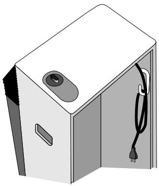
Fig. 6