VC-Dot 9 - Lighting MARTIN - Free user manual and instructions
Find the device manual for free VC-Dot 9 MARTIN in PDF.

User questions about VC-Dot 9 MARTIN
0 question about this device. Answer the ones you know or ask your own.
Ask a new question about this device
Download the instructions for your Lighting in PDF format for free! Find your manual VC-Dot 9 - MARTIN and take your electronic device back in hand. On this page are published all the documents necessary for the use of your device. VC-Dot 9 by MARTIN.
USER MANUAL VC-Dot 9 MARTIN
natural_image
Close-up of three black cable connectors with square connectors, no text or symbols visibleVC-Dots™ User Manual
Dimensions

Contents
Safety Information....4
Introduction 6
Elements in the VC-Dots™ system 6
System planning and installation....7
Important safety limits 7
Connection to a Martin P3 PowerPort 1500™ (P3 video system only) .....7
Connection to a 48 VDC PSU (DMX-controlled system only) 8
Hybrid cable link....8
Connection to a Martin VC-Feeder™ 8
Modifying Dot pitch and splicing VC-Dot strings 10
P3 system planning, installation and setup 11
P3 video system layout....11
General guidelines 12
P3 video system physical installation....12
P3 video system setup 12
DMX system planning, installation and setup 13
DMX system layout....13
General guidelines 14
DMX system physical installation....14
DMX system setup 14
Using the VC-DotsTM system....17
System status, testing and resetting 17
Testing and resetting.... 17
Service and maintenance....18
Cleaning. 18
Installing new software 18
Troubleshooting 19
Specifications 20
Safety Information

WARNING!
Read the safety precautions in this section before installing, powering, operating or servicing this product.
The following symbols are used to identify important safety information on the product and in this document:

Warning!
Safety hazard.
Risk of severe
injury or
death.

Warning!
Hazardous
voltage. Risk
of severe or
lethal electric
shock.
Warning!
Fire hazard.

Warning!
Refer to
manual before
installing,
powering or
servicing.

Warning! Read this user manual before installing and operating the VC-Dots™ system and keep this manual for future reference.

Warning! The VC-Dots™ system is designed to integrate with other Martin™ devices in a video display installation. Follow the safety precautions in this user manual and in the manuals of all the devices you connect to it. Observe all warnings in manuals and printed on devices. Install, connect and operate devices only as described in this manual and each device's manual, and only in accordance with local laws and regulations. All Martin™ manuals are supplied with devices and also available for download from www.martin.com.
Warning! The Martin™ VC-Dots™ system is not for household use. It presents risks of severe injury or death due to fire and burn hazards, electric shock and falls. It must be installed by qualified technicians only.
Warning! The VC-Dots™ system does not have user-serviceable parts. Refer any operation not described in this manual to Martin™ or its authorized service agents.
If you have any questions about how to operate the VC-Dots™ system safely, please contact your Martin™ supplier or call the Martin™ 24-hour service hotline on +45 8740 0000, or in the USA on 1-888-tech-180.
Protection from electric shock
- Check and respect the directions given in this user manual and the user manuals of all the devices that you intend to connect in the VC-Dots™ system, particularly the instructions, warnings and limits that apply to:
- system layout,
- specified cables,
- maximum cable lengths,
- maximum number of devices that can be connected, and
-
connections to other devices.
-
Note in particular that if you increase the pitch of a VC-Dots™ string by inserting Martin™ VC-Dots™ ribbon cable between Dots, you may have to remove Dots from the string in order to stay within safe limits.
-
Connect the VC-Dots™ system only to the Martin™ devices specified and installed as directed in this user manual.
-
Use only the cables and connectors specified by Martin™ to interconnect devices. If the specified cables are not long enough for an intended cable run, consult Martin™ for assistance in finding or creating a safe alternative cable
- Provide a means of locking out AC mains power that allows power to the installation to be shut down and made impossible to reapply, even accidentally, during work on the installation.
- Shut down power to the installation during service and when it is not in use.
- Before applying power to the installation, check that all power distribution equipment and cables are in perfect condition and rated for the current requirements of all connected devices.
- Isolate the installation from power immediately if a product, power cable or connector is in any way damaged, defective or wet, or if it shows signs of overheating.
Protection from burns and fire
- Provide free airflow and a minimum clearance of 10 mm (0.4 in.) around the front of VC-Dots.
- Do not operate the VC-Dots™ system if the ambient temperature (Ta) exceeds 55° C (131° F).
- Do not bend the VC-Dots™ system ribbon cable into a curve with a radius less than 26 mm (1 in.).
- Do not modify the VC-Dots™ system in any way not described in this manual or install other than genuine Martin™ parts. Use only accessories approved by Martin™.

Protection from injury
- When installing the VC-Dots™ system above ground level, ensure that the installation hardware and supporting structure can hold at least 10 times the weight of all the devices they support.
- In an overhead installation or where the VC-Dots™ system may cause injury if it falls:
- block access below the work area and work from a stable platform whenever installing, servicing or moving the VC-Dots™ system, and
- as soon as work is completed, check that all hardware and components are securely in place and fastened to supporting structures.
Introduction
Thank you for selecting the Martin VC-Dots™ system. VC-Dots™ pre-cabled chains of compact LED-based display modules are designed to integrate as pixels in a Martin P3™ video display system or display DMX-controlled lighting effects. Using Martin VC-Feeder™ devices to relay power and data to VC-Dots™, the system automatically recognizes either a Martin P3™ or a DMX data signal.
Used with or without a front diffuser, VC-Dots with their integrated hybrid power and data cabling system can be installed in almost any configuration with 3-dimensional freedom, easy setup and minimal cabling.
The VC-Dots ^TM system ^TM features include:
- Choice of 1-, 4- or 9-LED version Dots (different versions can be mixed in one installation)
• High-quality 16-bit per color image processing technology - Pixel-level brightness and color calibration for optimal image quality
- P3 and DMX/RDM control, with automatic protocol detection
- Intuitive pixel mapping and addressing using Martin P3 ^TM system controller
- Single hybrid power and data cable
- RGB, WW (warm white), MW (medium white) and CW (cool white) versions
- External power and data processor (Martin P3 PowerPort 1500™) and simple cabling system
Martin™ user documentation is supplied with products and available for download from the Martin™ website at http://www.martin.com, where you can also find the latest specifications, firmware updates and support information for all Martin™ products.
Martin™ welcomes input from users. Comments or suggestions regarding this manual can be e-mailed to service@martin.dk or posted to: Technical Documentation, Martin Professional A/S, Olof Palmes Allé 18, DK-8200 Aarhus N, Denmark.
Elements in the VC-Dots™ system
For overviews of the VC-Dots™ system used for Martin P3™ video display and DMX-controlled lighting display, see Figure 2 on page 11 and Figure 3 on page 13. The system consists of:
- Strings of Martin VC-Dot™ LED modules on ribbon cable that carries both data and 15 VDC power. LED modules are available in versions with one, four or nine LEDs and in RGB three-color as well as WW (warm white), MW (medium white) and CW (cool white) single-color versions. LED modules are simply called Dots in this manual.
Strings can be cut and can be extended using the extra ribbon cable and IP65 splice connectors available from Martin™.
- Martin VC-Feeder™ devices that accept Martin P3™ and DMX data as well as 48 VDC power and send data and 15 VDC power to VC-Dot strings.
In Martin P3 ^TM video display systems:
- Martin P3 PowerPort 1500™ devices that accept Martin P3™ video data and AC mains power and send data and 48 VDC power to VC-Feeders in video display systems.
- Martin P3 ^TM system controllers that accept a video source and send Martin P3 ^TM video data to LED-based display systems.
And in DMX-controlled display systems:
- RDM-compliant DMX controllers (Martin™ can supply various suitable hardware consoles or Windows PC software applications).
• 48 VDC external Power Supply Units.
- In larger installations, Martin RDM 5.5™ Splitters, optically isolated amplifier-splitters that allow a DMX / RDM data link to be split into branches.
Martin ^™ also supplies all the necessary cables and connectors for the VC-Dots ^™ system.
System planning and installation

Warning! Read "Safety Information" starting on page 4 and observe all the safety precautions given in this manual and in the manuals of the other devices in the system before planning or installing the system. If you are in any doubt about system safety, or you plan to install VC-Dots™ in a configuration that is not covered in this section, contact your Martin™ supplier for assistance.

Warning! Connect the VC-Dots™ system using only the devices and the cables specified in this manual. Do not exceed the maximum numbers of devices that can be connected and the maximum cable lengths specified in this manual and in the manuals of the other devices in the system. Note that if you increase Dot pitch by inserting extra ribbon cable from Martin™ on a VC-Dot string, you may have to remove Dots from the string in order to stay within safe limits.
Warning! Do not bend the VC-Dots ribbon cable into a curve of less than 26 mm (1 in.) radius.
Besides answering any questions that you might have about safety, your Martin™ supplier will be glad to advise If you would like assistance creating a VC-Dots installation.
For ordering information for devices, cables and other accessories, see the specifications at the end of this manual.
For a schematic overview of a Martin P3 ^™ video display installation, see Figure 2 on page 11.
For a schematic overview of a DMX-controlled installation, see Figure 3 on page 13.
Important safety limits

Warning! To avoid the risk of fire or electrical faults, a VC Dots installation must respect safety limits that ensure that cables and devices are not overloaded. Because the system is so flexible, you must plan a system layout that stays within these limits before installing the system. Read the following section carefully and do not exceed the limits given. If two different maximum limits apply to a configuration, you must always respect the lower limit.
Connection to a Martin P3 PowerPort 1500™ (P3 video system only)
The maximum number of VC-Dots that you can safely connect to a Martin P3 PowerPort 1500 ^™ in a P3 video display installation varies depending on the type of VC-Dot. Do not exceed the maximum limits given in Table 1:
VC-Dot 1
| Maximum number of Dots in total connected to all the outputs of a P3 PowerPort 1500 1200 | |
| Maximum number of Dots connected to any one output of a P3 PowerPort 1500 300 |
VC-Dot 4
| Maximum number of Dots in total connected to all the outputs of a P3 PowerPort 1500 768 | |
| Maximum number of Dots connected to any one output of a P3 PowerPort 1500 192 |
VC-Dot 9
| Maximum number of Dots in total connected to all the outputs of a P3 PowerPort 1500 432 | |
| Maximum number of Dots connected to any one output of a P3 PowerPort 1500 108 |
Table 1. Maximum number of VC-Dots connected to Martin P3 PowerPort 1500 ^TM
Connection to a 48 VDC PSU (DMX-controlled system only)
One or more 48 VDC external PSUs (power supply units) are required to supply DC power to VC-Feeders and then to VC-Dots in a DMX-controlled VC-Dots installation. The maximum number of VC-Dots that you can safely connect to an external PSU in a DMX-controlled system installation varies depending on the power rating of the PSU and the type of VC-Dot.
Check the maximum power rating of each PSU. The total power consumption of the VC-Dots that you supply with power via a PSU must not exceed the PSU's maximum power rating. To determine the total power consumption of a chain of VC-Dots, add together the power consumption of all the individual Dots using the figures given below (the figures make allowance for cable resistance, etc.):
- Allow 1.2 W per VC-Dot 1
- Allow 1.9 W per VC-Dot 4
- Allow 3.4 W per VC-Dot 9
Each time the total power consumption of the VC-Dots that you connect to a PSU reaches the PSU's maximum power rating, use a new PSU connected to a new VC-Feeder or chain of VC-Feeders.
Note that you may have to remove VC-Dots from the strings supplied by Martin™ by cutting the ribbon cable to make sure that strings do not exceed the PSU's maximum power rating. The lengths of VC-Dot string that you remove can be re-used (see "Modifying Dot pitch and splicing VC-Dot strings" on page 10).
Hybrid cable link
The maximum safe length for any one hybrid (power and data) cable link from either:
- a Martin P3 PowerPort 1500™ in a P3 video display installation or
- a 48 VDC external PSU in a DMX-controlled installation.
to either:
- a single VC-Feeder that is not linked to other VC-Feeders in a chain (C ^1 in Figure 2 on page 11) or
- the last VC-Feeder on a chain of VC-Feeders (total of C^1 +C^2 +C^2 etc. in Figure 2 on page 11)
is 50 m (164 ft.). Do not exceed this limit.
Connection to a Martin VC-Feeder™
Do not try to connect more than one string of VC-Dots to one VC-Feeder.
The maximum safe number of VC-Dots that you can safely connect in a string to one VC-Feeder depends on three factors:
• Type of VC-Dot (VC-Dot 1, 4 or 9),
- Lead-in cable length, and
- Dot pitch
Table 2 on page 9 gives the safe limits for different combinations of these three factors. Do not exceed these limits.
Type of VC-Dot
Larger VC-Dots consume more power, so the maximum number of Dots on a string can vary for VC-Dot 1, VC-Dot 4 or VC-Dot 9 strings.
Lead-in cable length
The length of a VC-Dot string's lead-in (the distance between the VC-Feeder and the first Dot) affects the maximum number of Dots for the string.
The maximum possible lead-in cable length from the VC-Feeder to the first Dot on a string is 5000 mm (16.4 ft.). Standard VC-Dot strings are supplied with a 2000 mm (6.6 ft.) lead-in. Martin™ can supply strings with a 5000 mm (16.4 ft.) lead-in to special order. Please consult your Martin™ supplier for details.
Dot pitch
The Dot pitch of a VC-Dot string is the center-to-center distance between the Dots on the string.
VC-Dots are supplied in strings with the following Dot pitches as standard:
• VC-Dot 1: 100 mm (3.9 in.)
• VC-Dot 4: 200 mm (7.9 in.)
• VC-Dot 9: 400 mm (15.7 in.)
Martin™ can manufacture VC-Dot strings with non-standard Dot pitches to special order. Please consult your Martin™ supplier for details.
It is possible for the user to reduce or increase the Dot pitch of a string by removing or inserting lengths of VC-Dot ribbon cable between Dots (see "Modifying Dot pitch and splicing VC-Dot strings" later in this section).
If you increase Dot pitch (make a string longer by inserting lengths of ribbon cable between Dots), or if you place a special order for strings with increased Dot pitch from Martin™, the maximum number of Dots on the string is reduced. Table 2 gives the limits at different Dot pitches for the number of Dots on one string. Do not exceed these limits:
VC-Dot 1: maximum number of Dots per string
Lead-in cable length: 2000
| Dot pitch (cable length between Dots on string) 50 100 200 | 300 | 400 | 500 | 600 | 700 | 800 | 900 | 1000 | |||||
| Maximum number of Dots per string connected to one VC-Feeder | 100 | 100 | 100 | 100 | 100 | 100 | 100 | 100 | 95 | 90 |
Lead-in cable length: 5000
| Dot pitch (cable length between Dots on string) 50 100 200 | 300 | 400 | 500 | 600 | 700 | 800 | 900 | 1000 | |||||
| Maximum number of Dots per string connected to one VC-Feeder | 100 | 100 | 100 | 100 | 100 | 100 | 100 | 100 | 96 | 91 | 87 |
VC-Dot 4: maximum number of Dots per string
Lead-in cable length: 2000
| Dot pitch (cable length between Dots on string) 100 200 4 | 00 600 | 800 10 | 000 12 | 00 1400 | 1600 | 1800 | 2000 | ||||
| Maximum number of Dots per string connected to one VC-Feeder | 64 64 | 64 64 | 64 59 | 54 51 | 48 45 | 43 |
Lead-in cable length: 5000
| Dot pitch (cable length between Dots on string) 100 200 4 | 00 600 | 800 10 | 000 12 | 00 1400 | 1600 | 1800 | 2000 | ||||
| Maximum number of Dots per string connected to one VC-Feeder | 64 64 | 64 64 | 64 56 | 52 49 | 46 43 | 41 |
VC-Dot 9: maximum number of Dots per string
Lead-in cable length: 2000
| Dot pitch (cable length between Dots on string) 100 200 4 | 400 600 | 800 1000 12 | 00 1400 | 1600 | 1800 | 2000 | ||||
| Maximum number of Dots per string connected to one VC-Feeder | 36 36 | 36 35 | 31 29 | 26 25 | 23 22 | 21 |
Lead-in cable length: 5000
| Dot pitch (cable length between Dots on string) 100 200 4 | 00 600 | 800 1000 | 1200 | 1400 | 1600 | 1800 | 2000 | ||||
| Maximum number of Dots per string connected to one VC-Feeder | 36 36 | 36 31 | 28 26 | 24 23 | 21 20 | 20 |
All lengths are given in millimeters
Table 2. Dot pitch and maximum number of Dots per string
Note that, if you increase Dot pitch yourself, you may have to remove Dots from the strings supplied by Martin ^™ in order to stay within safe limits.
Modifying Dot pitch and splicing VC-Dot strings
You can increase or reduce the pitch of standard VC-Dot strings by cutting the ribbon cable between Dots and extending or shortening the cable. To extend the cable, insert lengths of the ribbon cable available as an accessory from Martin™. To connect cuts in cables, use the IP65-rated quick splice connectors available as accessories from Martin™ (see "Accessories" on page 22). Connectors can be installed once only. Do not try to re-use them.
If you increase Dot pitch, respect the safety limits given in Table 2 on page 9.
If you reduce Dot pitch, you do not need to respect a minimum pitch limit and the maximum number of Dots per string is the same as for a standard VC-Dot string:
- VC-Dot 1: 100 Dots
- VC-Dot 4: 64 Dots
- VC-Dot 9: 36 Dots
To cut ribbon cable:
- Check that the cable is not connected to power.
- Make a clean, square cut across the ribbon cable using sharp good-quality cutting pliers.
To splice ribbon cable:
- Check that the cable is not connected to power.
- The ribbon cable consists of six wires. Separate the wires from each other for the last few centimeters (couple of inches) at the ends of the ribbon cable.
- Place the cut cables end-to-end on a flat surface. The Dots on either side of the cut ends must face the same way and the ribbon cable must not be twisted. Organize the wire ends into pairs, with each wire in one cable lined up end-to-end with the same wire in the other cable.
- See Figure 1. Do not strip insulation from wire ends. Push two matching pairs of wire ends into a splice connector until the ends touch the center wall inside the connector (A). Holding the wires in position, use water-pump pliers to press the terminal clamps into the connector (B) until the tops of the clamps are level with the transparent connector body (C).
- Check that wires are still pressed fully into the connector (D). If there is a gap between wire ends (E), cut off the end of the ribbon cable and the connector, scrap them and start again with a new connector.

text_image
Diagram illustrating five stages of cable connection and safety inspection, labeled A through E with check and cross icons.Figure 1: Splicing ribbon cable
- Finally, make a visual check that the connector is not damaged in any way. Check that the terminals inside the connector are not bent or misaligned and that no loose strands of copper are visible. If a connector is not correctly installed and in perfect condition, cut off the end of the ribbon cable and the connector, scrap them and start again with a new connector.
- Continue splicing the ribbon cable as described above until each wire in one ribbon cable is safely connected to the same wire in the other ribbon cable.
P3 system planning, installation and setup
P3 video system layout
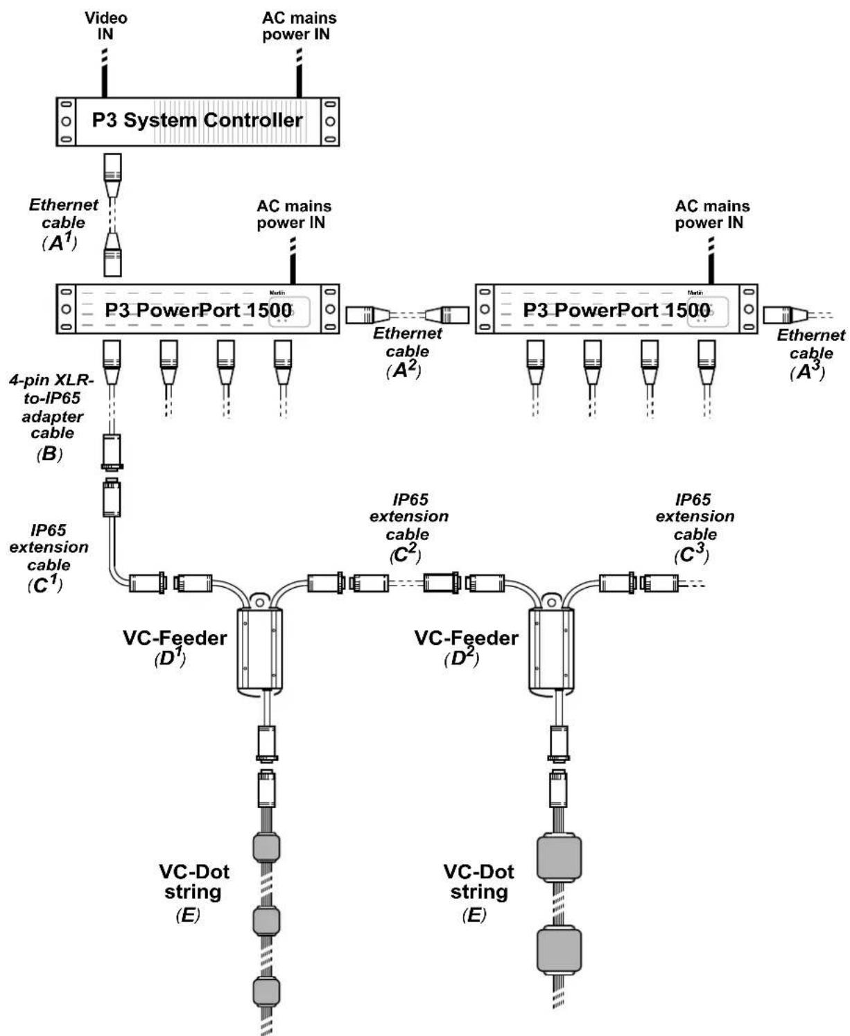
Figure 2 gives a schematic overview of a VC-Dots™ system for P3 video display.
flowchart
graph TD
    A["P3 System Controller"] --> B["AC mains power IN"]
    B --> C["Ethernet cable (A¹)"]
    C --> D["P3 PowerPort 1500"]
    D --> E["4-pin XLR-to-IP65 adapter cable (B)"]
    D --> F["IP65 extension cable (C¹)"]
    D --> G["VC-Feeder (D¹)"]
    D --> H["VC-Feeder (D²)"]
    D --> I["VC-Dot string (E)"]
    D --> J["VC-Dot string (E)"]
    D --> K["Ethernet cable (A²)"]
    D --> L["Ethernet cable (A³)"]
    D --> M["AC mains power IN"]
    D --> N["P3 PowerPort 1500"]
    N --> O["IP65 extension cable (C²)"]
    N --> P["IP65 extension cable (C³)"]
Figure 2: P3 video system layout
General guidelines
Ethernet Cat 5e or better cable is required for the P3 video data link (A in Figure 2).
A P3 video data link cable run (A in Figure 2) between any two devices on the link can be up to 100 m (328 ft.) in length. If necessary, a cable run can be extended beyond 100 m by inserting an unmanaged Ethernet switch or using a fiber-optic system (see the P3 ^TM system controller user manual for details).
You can connect up to fifty P3 PowerPort 1500s in a P3 data daisy-chain (A in Figure 2). If you need to connect more than fifty, use an unmanaged Ethernet switch to split the P3 data link into chains, each containing maximum fifty P3 PowerPort 1500s.
P3 video system physical installation
To create an installation that displays Martin P3 ^TM video on a VC-Dots ^TM system:
- Make sure that no part of the installation can be connected to AC mains power until all work is complete.
- Work with a plan of the installation that respects the limits given in "Important safety limits" on page 7.
-
Mount the strings of VC-Dots and the other devices in the installation:
-
Hold each string of VC-Dots in place and mark up installation positions, then install them on the mounting surface. You can fasten the optional mounting clips available from Martin™ to the surface and then install each VC-Dot in a clip.
-
Mount the other devices in the installation as directed in their user manuals.
-
See Figure 2. Create a P3 video data link from the Martin P3 ^™ system controller to a Martin P3 PowerPort 1500 ^™ using Ethernet Cat 5e or better network cable A ^1 .
- If required, continue the P3 video data link in a daisy-chain by connecting the P3 data throughput of the first P3 PowerPort 1500 ^™ to the P3 data input of the next as described in the P3 PowerPort 1500 ^™ user manual A ^2 , A ^3 , etc.
- Connect a Martin™ 4-pin XLR-to-IP65 adaptor cable, P/N 11840165 B to the first combined power and data output of the first P3 PowerPort 1500.
- Either connect the adapter cable B directly to the first VC-Feeder D ^1 in the installation, or if necessary connect it to a Martin ^™ hybrid IP65-to-IP65 extension cable C ^1 and then to the first VC-Feeder D ^1 . Hybrid IP65-to-IP65 extension cables are available from Martin ^™ in various lengths (see "Accessories" on page 22).
- If required, continue installing VC-Feeders™ on the hybrid link, connecting them in a daisy-chain either directly or using Martin™ hybrid extension cables C^2 , C^3 , etc. Connect each cable from the THRU connector on one VC-Feeder to the IN connector on the next VC-Feeder.
- Connect VC-Dot strings to the OUT connector cable tails on the VC-Feeders.
-
When all devices and cables are physically installed and connected, you can set up and test the installation:
-
Connect the Martin P3 PowerPort 1500™ to AC mains power at 100 - 240 V, 50/60 Hz as described in the P3 PowerPort 1500™ user manual.
- Connect the Martin P3 system controller to AC mains power and power the controller on.
- Test the VC-Dot strings using the control button on VC-Feeders (see the VC-Feeder user manual for details).
P3 video system setup
Set up the VC-Dots video addressing and display configuration on the P3 system controller. You can also send test patterns to the installation from the P3 system controller. See the controller's user manual for details.
DMX system planning, installation and setup
DMX system layout
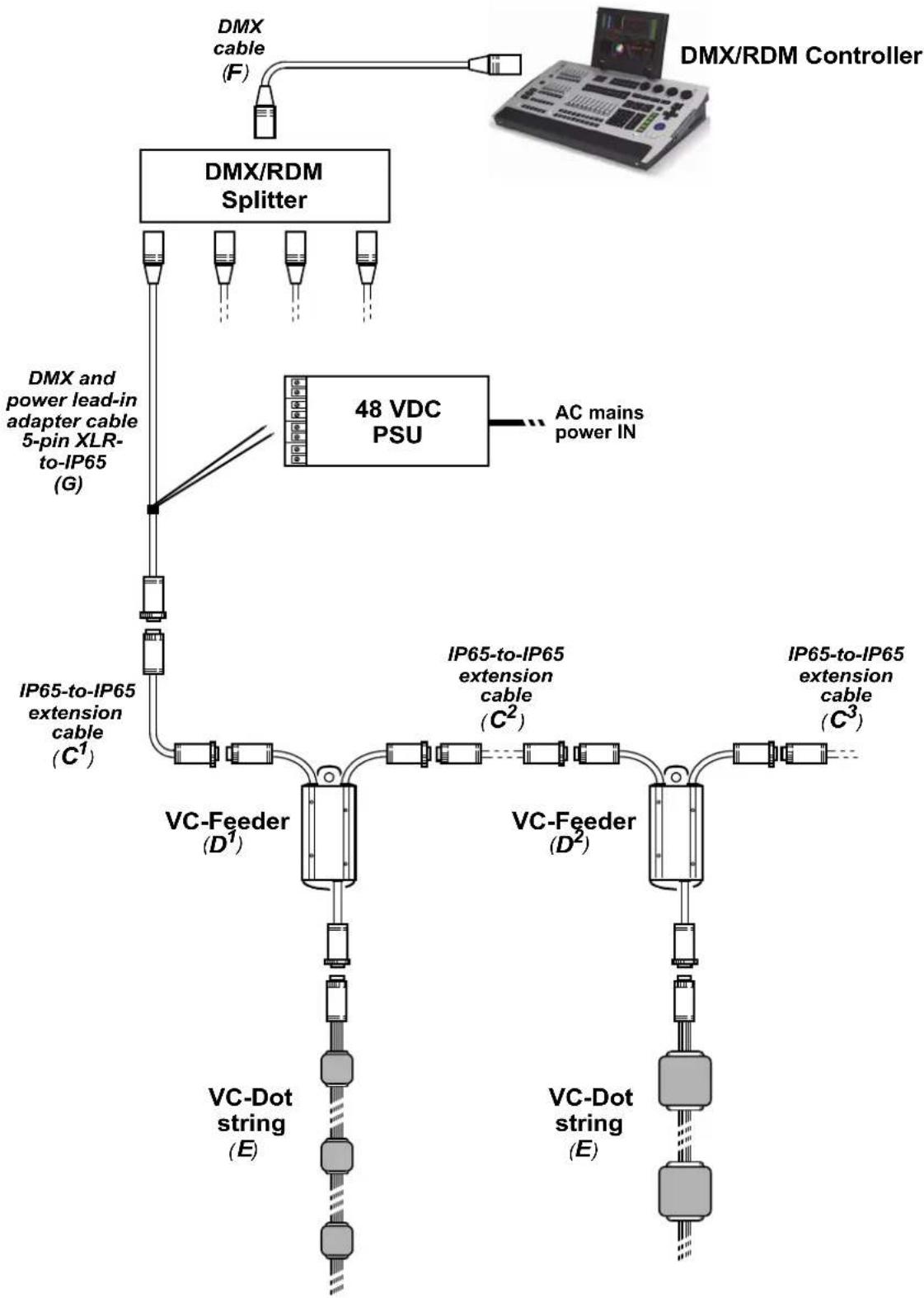
Figure 2 gives a schematic overview of a VC-Dots™ system for DMX-controlled lighting effects.
flowchart
graph TD
    A["DMX/RDM Splitter"] --> B["48 VDC PSU"]
    B --> C["AC mains power IN"]
    D["DMX"] --> A
    E["DMX/RDM Controller"] --> A
    F["IP65-to-IP65 extension cable (C¹)"] --> G["VC-Feeder (D¹)"]
    G --> H["VC-Dot string (E)"]
    I["IP65-to-IP65 extension cable (C²)"] --> J["VC-Feeder (D²)"]
    J --> K["VC-Dot string (E)"]
    L["ICAM"] --> M["Computer"]
Figure 3: DMX system layout
General guidelines
Good-quality DMX cable is required for the DMX data link (see F in Figure 3). The link can be maximum 300 m (1000 ft.) in length from the first device to the last device on the link, but this can be extended using an amplifier/splitter such as the Martin RDM 5.5 Splitter™, P/N 90758150.
The number of VC-Dots that you can connect to one hybrid link of daisy-chained VC-Feeders carrying DMX data is limited by the 512 DMX channels available in one DMX universe at the DMX controller. Each time you reach 512 channels, you will need to create a new hybrid link of daisy-chained VC-Feeders that are controlled in a new DMX universe.
DMX system physical installation
To create an installation that displays DMX-controlled lighting effects on a VC-Dots™ system:
- Make sure that no part of the installation can be connected to AC mains power until all work is complete.
- Work with a plan of the installation that respects the limits given in "Important safety limits" on page 7.
-
Mount the strings of VC-Dots and the other devices in the installation:
-
Hold each string of VC-Dots in place and mark up installation positions, then install them on the mounting surface. You can fasten the optional mounting clips available from Martin™ to the surface and then install each VC-Dot in a clip.
-
Mount the other devices in the installation as directed in their user manuals.
-
See Figure 3. Run a DMX cable F from a DMX/RDM controller such as the Martin M1 ^TM or M-PC ^TM to a Martin RDM 5.5 Splitter (P/N 90758150).
In smaller installations a Splitter may not be necessary. In this case, you will connect the DMX cable F directly to the hybrid DMX and power lead-in cable G in the next step.
- Connect a Martin™ hybrid DMX and power lead-in 5-pin XLR-to-IP65 adapter cable, P/N 11840174 G to the first output of the Splitter, if used. If not using a Splitter, connect the hybrid lead-in adapter cable G directly to the DMX cable F.
- Connect the two DC power input wires on the DMX and power lead-in cable G to an external 48 VDC external power supply unit (PSU) such as the Mean Well SP-480 48. Connect the white wire to a positive (+ve) 48 V output and the black wire to a negative (-ve) 48 V output.
- Either connect the power lead-in adapter cable G directly to the first VC-Feeder D ^1 in the installation, or if necessary connect it to a Martin ^™ hybrid IP65-to-IP65 extension cable C ^1 and then to the VC-Feeder D ^1 .
Hybrid IP65-to-IP65 extension cables are available from Martin™ in various lengths (see "Accessories" on page 22).
- If required, continue installing VC-Feeders™ on the hybrid link, connecting them in a daisy-chain either directly to each other or by inserting Martin™ hybrid IP65-to-IP65 extension cables C^2 , C^3 , etc. Connect each cable from the THRU connector on one VC-Feeder to the IN connector on the next VC-Feeder.
Remember that, each time a daisy-chain of VC-Dots uses all the 512 control channels available in one DMX universe (see "DMX control channels" later in this section), you must create a new hybrid link for a new DMX universe, starting at a new output at the DMX controller.
-
Connect VC-Dot strings E to the OUT connector cable tails on the VC-Feeders D.
-
When all devices and cables are physically installed and connected, you can set up and test the installation:
-
Connect the external PSU to AC mains power as described in its user manual.
- Connect the DMX controller to AC mains power and power the controller on.
- Test the VC-Dot strings using the control button on VC-Feeders (see the VC-Feeder user manual for details).
DMX system setup
A DMX system gives 0 - 100% variable intensity control. Varying the intensity of red, blue and green LEDs in RGB products provides RGB color mixing.
You can set up and control a VC-Dots™ installation over the data link using an RDM-compatible DMX controller such as the Martin M-PC™ Windows application (running on a PC connected to a USB/DMX interface box such as the Martin USB Duo™ DMX Interface) or the Martin M1™ DMX/RDM control console.
The user interface on the monitor screen of a Martin M1 ^TM console and on a PC running Martin M-PC ^TM is basically identical.
You can test a VC-Dot string using the Test button on the VC-Feeder that the string is connected to.
DMX control channels
DMX controllers send control data on DMX control channels in DMX universes. One DMX universe has 512 channels available. RGB control of each individually controlled element in an installation requires three channels, white intensity control requires one channel.
A VC-Dots™ installation can be controlled as groups of pixels or as individual pixels:
- A group can consist of an entire installation, any part of an installation or a VC-Dots™ string. In grouped control, all the LEDs in one group are controlled using the same DMX channels – three channels for RGB products and one channel for WW, MW and CW products.
- If VC-Dots™ are set up for individual pixel control, each of the Dots on a string is controlled by its own DMX channels.
A VC-Dots™ installation uses the number of DMX channels required by the group or pixel (three channels for RGB and one channel for WW, MW or CW) multiplied by the total number of groups or pixels in the installation. For example, an installation with three VC-Dot 9 RGB strings, each with 36 Dots (108 Dots in total), will require:
- 3 DMX channels if the entire installation is controlled as one group,
- 3 DMX channels x 3 strings = 9 DMX channels if the installation is divided into three strings and each string is individually controlled as one group,
- 3 DMX channels x 3 strings x 36 pixels = 324 DMX channels if each of the 108 Dots is individually controlled as a pixel.
Individual and grouped control can be mixed freely in an installation. For example, some VC-Dots ^™ can be set up for individual pixel control, other Dots can be set up for individual module control, and other Dots can be put into groups for grouped control of multiple modules.
If the number of DMX channels required in the installation exceeds the 512 channels available in one DMX universe, you will need to set up additional DMX universes at your controller and create a separate data link for each DMX universe. See your DMX controller user manual for details. Your Martin™ supplier will also be happy to help you if you need assistance.
DMX addresses
The system must be set up so that each individually controlled group or pixel receives instructions from the DMX controller on its own DMX channels. The DMX address, also known as the control address or start channel, is the first of these channels. If a unit uses more than one channel, it uses the DMX address channel and the channels immediately above it. For example, one VC-Dots™ RGB string controlled as one group and set to DMX address 1 will use DMX channels 1 - 3. Channel 4 will be available for use as a DMX address for the next group or pixel.
If a VC Dots™ RGB string is set to individual pixel control (see "Setting strings to grouped or pixel control modes" on page 16), the Dots on the string are given DMX addresses in ascending order starting from the first Dot on the string (the first Dot after the VC-Feeder). For example, if a VC-Dot 9™ RGB string is set to pixel control and set to DMX address 1, each of the 36 Dots will use 3 channels, and the string will use DMX channels 1 - 108 (Channel 1 -3 for the first pixel, channels 4 - 6 for the next pixel etc. until it reaches channels 106 - 108 for the last pixel at the end of the string. Channel 109 will be available for use as a DMX address for the next group or pixel.
If a VC Dots™ RGB string is set to string control (see "Setting strings to grouped or pixel control modes" on page 16), it can be controlled as an individual string or assigned to a group of strings. To create a group of strings, give them the same DMX address. All strings that have the same DMX address will receive the same instructions and behave identically.
Setting up via RDM using Martin M-PC ^TM
Using an RDM-compliant DMX controller such as Martin M-PC ^™ , you can communicate with the VC-Dots ^™ system on the DMX data link via RDM. You can:
- Retrieve data
- Set the DMX addresses of the groups or pixels on the link
- Apply various setup options.
To use Martin M-PC, connect a PC running this application to the data link using the Martin USB Duo™ USB/DMX interface box.
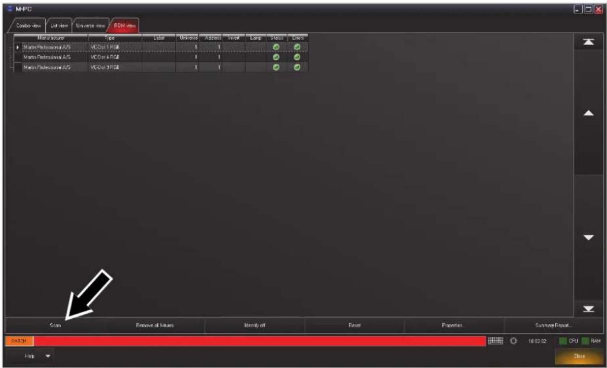
See Figure 4. Open the RDM View window in M-PC and click on the Scan button (arrowed bottom left) to display a list of the RDM-compliant devices on the DMX/RDM data link (in this example, three strings are present on the link, and all three strings are set to DMX address 1).
Identifying VC-Dot strings in the installation
To see which VC-Dot string in this list corresponds to which string in the installation, click on each string in the list once to select it, then click on the Identify button at the bottom of the screen. The string in the installation that corresponds to the selected string in the list will flash a signal so that you can identify it.
text_image
M-PC Combo view List view Universe view RDM view Manufacturer Type Label Universe Address Inverter Lamp Status Error Martin Professional A/S VCCor 1 RGB 1 1 Martin Professional A/S VCCor 4 RGB 1 1 Martin Professional A/S VCCor 9 RGB 1 1 Start Remove all values Identity off Reset Properties Summary Report... MATCH 16:02:02 CPU RAM CloseFigure 4: M-PC RDM View
Setting DMX Addresses
See Figure 4. To set DMX addresses using the M-PC application, open the RDM View window and click on Scan to display a list of the elements in the installation. Click in the Address box for each VC-Dot string and enter the desired DMX address, then press the Enter key to store the DMX address for that string. Remember that strings with identical addresses will receive the same instructions.
When working with more than one DMX universe, click in the Universe box for each VC-Dot string, enter the desired DMX universe number, then press the Enter key to store the DMX universe for that string.
Setting strings to grouped or pixel control modes
In pixel mode, the Dots on a string are controlled individually. In string mode, All the Dots on one string are controlled as one group.
To set a VC-Dot string to pixel or string mode, calibrated or raw, using M-PC, open the RDM View window and click on Scan to display a list of the elements in the installation. Select the string in the list, then click on the Properties... button at the bottom of the screen to open the Properties window for that string. Select from:
- Pixel mode (calibrated) – this is the default setting
• String mode (calibrated) - Pixel mode (raw)
- String mode (raw)
Calibrated and raw modes
See the section on setting control modes above:
- In calibrated mode, color and intensity levels are evenly matched in different LEDs and different strings but maximum output is slightly reduced.
- In raw mode, LEDs give maximum possible output but color and intensity levels may be slightly uneven in different LEDs and different strings.
Using the VC-Dots™ system

Warning! Before applying power to the VC-Dots™ system:
- Carefully review the safety information starting on page 4
- Check that the installation is safe and secure.
Do not use the VC-Dots™ system if the ambient temperature exceeds 55°C (131°F) or falls below -20°C (-4°F).
System status, testing and resetting
The multi-color status LED on the VC-Feeder gives system status information. See the VC-Feeder user manual for details.
Testing and resetting
The control button on the VC-Feeder lets you test the VC-Dot string connected to the VC-Feeder and reset the system. Test patterns are stored in the VC-Feeder's memory, so an external controller is not required for testing.
Table 3 below lists the control button functions:
| Button action Function | |
| Short press | Display the following test patterns on the VC Dots (one short press scrolls to next pattern):- Calibrated white- Full red- Full green- Full blue- Scrolling gradient |
| Press and hold until VC-Feeder status LED lights blue | Reboot the VC-Feeder. |
| Press and hold until VC-Feeder status LED lights white | Return the VC-Feeder to its default factory firmware. |
Table 3: Key to control button functions
Note that test patterns can also be called up on P3 system controllers and the P3 PowerPort 1500 ^TM .
Service and maintenance

Warning! Read "Safety Information" on page 4 before carrying out service on the VC-Dots™ system.
Warning! Isolate the installation from AC mains power before servicing.
Warning! Refer any service operation not described in this manual to a qualified service technician.
Important! Excessive dust and dirt buildup causes overheating that will damage the product. Damage caused by inadequate cleaning is not covered by the product warranty.
The user will need to clean the VC-Dots ^™ system periodically. All other service operations on the VC-Dots ^™ system must be carried out by Martin Professional ^™ or its approved service agents.
Installation, on-site service and maintenance can be provided worldwide by the Martin Professional Global Service organization and its approved agents, giving owners access to Martin's expertise and product knowledge in a partnership that will ensure the highest level of performance throughout the product's lifetime. Please contact your Martin supplier for details.
The characteristics of all LEDs change very gradually over extended periods of time, and not all colors change at the same rate. Rates of change vary depending on factors such as temperature and how intensively a particular color is used over many thousands of hours. The changes mean that overall light output and the exact hues obtained from LED-based products can be expected to shift slightly over time.
To help you obtain consistent output despite these changes, Martin P3 software from version 4.1.0 contains the P3 Fixture Adjuster tool. This feature lets you compensate for changes in LED characteristics and restore initial output and color authenticity levels. Please contact Martin™ for more details.
Cleaning
Cleaning schedules vary greatly depending on the operating environment. It is therefore impossible to specify precise cleaning intervals for the VC-Dots™ system. In extreme cases, the product may require cleaning after surprisingly few hours of operation. Environmental factors that may result in a need for frequent cleaning include:
- Use of smoke or fog machines.
- High airflow rates (near air conditioning vents, for example).
• Presence of cigarette smoke. - Airborne dust (from stage effects, building structures and fittings or the natural environment in outdoor locations, for example).
If one or more of these factors is present, inspect products soon after installing them to see whether cleaning is necessary. Check again at frequent intervals. This procedure will allow you to assess cleaning requirements in your particular situation. If in doubt, consult your Martin™ dealer about a suitable cleaning schedule.
To clean the VC-Dots™ system, use low-pressure compressed air to remove dust and loose particles from the Dots. If necessary, wipe the Dots with a cloth dampened in a detergent solution. Do not use caustic, abrasive or solvent-based cleaning products. Do not spray Dots with a high-pressure water jet. Clean other devices as directed in their user manuals.
Installing new software
It may be necessary to upload new software (i.e. device firmware) to the VC-Feeder if the VC-Feeder and VC-Dots appear to have a software-related fault or if you want to update to a newer software version.
Software for Martin™ products is available from the Martin website. The VC-Feeder software can be installed from the P3 System Controller over the P3 data link. See the P3 System Controller user manual for software installation instructions.
Troubleshooting
| Problem Probable cause(s) Remedy | ||
| Control is lost and VC-Feeder status LED lights constant or flashing red. | Error has occurred. | Check that system is correctly connected, set up and running.Hold control button pressed in until it turns blue, then release to reboot VC-Feeder.Restart P3 or DMX controller. |
| VC-Feeder and/or VC-Dots are completely dead. | No DC power to VC-Feeder and/or VC-Dots. | Check 48 VDC power supply and cables |
| Internal fault. | Disconnect from power. Do not attempt repairs yourself. Contact MartinTM Service or an authorized MartinTM service partner for assistance. | |
| VC-DotsTM system does not display as intended. | Bad 48 VDC power transmission. | Inspect connections and cables. Correct poor connections. Repair or replace damaged cables. |
| Bad data transmission. | Inspect connections and cables. Correct poor connections. Repair or replace damaged cables. | |
| Incorrect mapping or addressing of VC-Dots. | Check address and controller settings. | |
| Product in installation is defective and is disturbing data transmission. | Substitute known good products one at a time until normal operation is regained. Have faulty product serviced by MartinTM Service. | |
Table 4: Troubleshooting
Specifications
Physical
VC-Dot 1 ^TM
Dot dimensions (LxWxH) 28 mm (1.1 in.) x 23 mm (0.9 in.) x 11 mm (0.4 in.
Dot dimensions with dome (LxWxH) .....28 mm (1.1 in.) x 23 mm (0.9 in.) x 20 mm (0.8 in.)
Weight 1.3 kg (2.9 lbs.) for 100 Dots, 100 mm (3.9 in.) Dot pitch, with 2 m (6.6 ft.) lead-in cable and connector
Maximum number of Dots per string 100
Standard Dot pitch....100 mm (3.9 in.)
Minimum Dot pitch....50 mm (2.0 in.)
Maximum Dot pitch 1000 mm (39.4 in.)
Standard lead-in cable length 2000 mm (78.7 in.)
Maximum lead-in cable length....5000 mm (196.9 in.)
VC-Dot 4 ^TM
Dot dimensions (LxWxH)....36 mm (1.4 in.) x 30 mm (1.2 in.) x 13 mm (0.5 in.)
Dot dimensions with dome (LxWxH) .....36 mm (1.4 in.) x 30 mm (1.2 in.) x 27 mm (1.1 in.)
Weight 1.8 kg (4.0 lbs.) for 64 Dots, 200 mm (7.9 in.) Dot pitch, with 2 m (6.6 ft.) lead-in cable and connector
Maximum number of Dots per string 64
Standard Dot pitch....200 mm (7.9 in.)
Minimum Dot pitch....60 mm (2.4 in.)
Maximum Dot pitch 2000 m (78.7 in.)
Standard lead-in cable length .2000 mm (78.7 in.)
Maximum lead-in cable length....5000 mm (196.9 in.)
VC-Dot 9™
Dot dimensions (LxWxH)....48 mm (1.9 in.) x 40 mm (1.6 in.) x 13 mm (0.5 in.)
Dot dimensions with dome (LxWxH) .....48 mm (1.9 in.) x 40 mm (1.6 in.) x 31 mm (1.2 in.)
Weight 1.8 kg (4.0 lbs.) for 36 Dots, 400 mm (15.7 in.) Dot pitch, with 2 m (6.6 ft.) lead-in cable and connector
Maximum number of Dots per string 36
Standard Dot pitch....400 mm (15.7 in.)
Minimum Dot pitch....70 mm (2.8 in.)
Maximum Dot pitch 2000 m (78.7 in.)
Standard lead-in cable length 2000 mm (78.7 in.)
Maximum lead-in cable length....5000 mm (196.9 in.)
Dot pitch = Dot center-to-center distance
One Dot = one pixel
Control and programming
Control options.... Martin™ P3 System Controller (via Martin™ P3 PowerPort 1500) or DMX
DMX channels .... 3 per independently controlled RGB Dot, string or group, 1 per .... independently controlled WW, MW or CW Dot, string or group
Control modes. Calibrated and raw
Setting and addressing P3 System controller or RDM-compliant controller
Control resolution....16-bit (P3) or 8-bit (DMX) control of each color
Color and intensity calibration ....Dot-level
Video signal compliance .... Martin P3™ proprietary protocol
DMX compliance . . . . . . . . . . . . . . . . . . . . . . . . . . . . . . . . . . . . . . . . . . . . . . . . USITT DMX512-A
RDM compliance.... ANSI/ESTA E1.20
Control/user interface
Device status....Multi-color status on VC-Feeder™
Device testing ....Multi-function push button on VC-Feeder™
System Integration
Martin P3 PowerPort 1500™ P/N 90721040
Martin VC-Feeder™ P/N 90357040
Optics
Minimum LED lifetime 50 000 hours to >70% luminous output*
VC-Dot 1 ^TM light source....One RGB, WW, MW or CW LED
VC-Dot 4™ light source.... Four RGB, WW, MW or CW LEDs
VC-Dot 9™ light source....Nine RGB, WW, MW or CW LEDs
Viewing angle. 120^ × 120^
Viewing angle with dome 180^ × 180^
*Manufacturer's figure obtained under manufacturer's test conditions
For photometric data, see the Martin™ website at www.martin.com
Construction
Dot .... Clear polycarbonate, clear silicone filled
Diffuser dome .... White translucent polycarbonate
Mounting clip .... White polycarbonate
Interconnecting cable....6 x AWG20 ribbon, black
Minimum cable bend radius....26 mm (1.0 in.)
Protection rating.... IP67
RoHS compliant
Installation
Orientation....Any
Mounting .... Clip system
Connections
Power and data input to VC-Dot™ string from VC-Feeder™. . . . . . Custom 8-pin connector, IP67-rated
VC-Feeder™ in/thru. Custom 6-pin connector. IP65-rated
Electrical
All VC-Dots™
Nominal input voltage 15 VDC from Martin VC-Feeder™
VC-Dot 1 ^TM
Peak power consumption (at full intensity, full white)....0.95 W per Dot
Typical power consumption (with typical video content) 0.32 W per Dot
VC-Dot 4 ^TM
Peak power consumption (at full intensity, full white)....1.50 W per Dot
Typical power consumption (with typical video content) 0.50 W per Dot
VC-Dot 9 ^TM
Peak power consumption (at full intensity, full white)....2.75 W per Dot
Typical power consumption (with typical video content) 0.92 W per Dot
Thermal
Cooling. Convection
Maximum ambient temperature (Ta max.) 55° C (131° F)
Minimum ambient temperature (Ta min.) -20^ C ( -4^ F)
Approvals


EU safety....EN 60950-1
EU EMC ..... EN 55103-1, EN 55103-2, EN 55022,
EN 55024, EN 61000-3-2, EN 61000-3-3
US safety UL 60950-1
US EMC FCC Part 15 Class A
Canadian safety CSA C22.2 No. 60950-1
Canadian EMC. ICES-003 Class A
Australia/NZ C-Tick N424
Accessories
VC-Dot 1 ^TM installation accessories
VC-Dot 1™ Diffuser Domes, set of 10. P/N 90357180
VC-Dot 1™ Diffuser Domes, Smoked, set of 10 P/N 91610110
VC-Dot 1^TM Mounting Clips, set of 10 P/N 90357210
VC-Dot 1^TM Truss Clips, set of 10 P/N 91611371
VC-Dot 1™ Aluminum Mounting Profile, Black, 2 m (6.6 ft.) P/N 91611374
VC-Dot 1™ Mounting Profile Cover, Black, 2 m (6.6 ft.) P/N 91611375
VC-Dot 1 ^TM Mounting Profile End Caps, Black, set of 10 P/N 91611376
VC-Dot 1™ Mounting Profile Cable Entry End Caps, Black, set of 10 P/N 91611377
VC-Dot 1™ Aluminum Mounting Profile, Grey, 2 m (6.6 ft.). P/N 91611386
VC-Dot 1™ Mounting Profile Cover, Grey, 2 m (6.6 ft.) P/N 91611387
VC-Dot 1™ Mounting Profile End Caps, Grey, set of 10 P/N 91611388
VC-Dot 1™ Mounting Profile Cable Entry End Caps, Grey, set of 10 P/N 91611389
VC-Dot 4 ^TM installation accessories
VC-Dot 4™ Diffuser Domes, set of 10. P/N 90357190
VC-Dot 4^TM Diffuser Domes, Smoked, set of 10
VC-Dot 4^TM Mounting Clips, set of 10 P/N 90357220
VC-Dot 4^TM Truss Clips, set of 10 P/N 91611372
VC-Dot 4™ Aluminum Mounting Profile, Black, 2 m (6.6 ft.) P/N 91611378
VC-Dot 4™ Mounting Profile Cover, Black, 2 m (6.6 ft.) P/N 91611379
VC-Dot 4^TM Mounting Profile End Caps, Black, set of 10 P/N 91611380
VC-Dot 4™ Mounting Profile Cable Entry End Caps, Black, set of 10 P/N 91611381
VC-Dot 4™ Aluminum Mounting Profile, Grey, 2 m (6.6 ft.). P/N 91611390
VC-Dot 4™ Mounting Profile Cover, Grey, 2 m (6.6 ft.) P/N 91611391
VC-Dot 4™ Mounting Profile End Caps, Grey, set of 10 P/N 91611392
VC-Dot 4™ Mounting Profile Cable Entry End Caps, Grey, set of 10 P/N 91611393
VC-Dot 9 ^TM installation accessories
VC-Dot™ 9 Diffuser Domes, set of 10.... P/N 90357200
VC-Dot™ 9 Diffuser Domes, Smoked, set of 10 P/N 91610108
VC-DotTM 9 Mounting Clips, set of 10 P/N 90357170
VC-Dot 9™ Truss Clips, set of 10 P/N 91611373
VC-Dot 9™ Aluminum Mounting Profile, Black, 2 m (6.6 ft.) P/N 91611382
VC-Dot 9™ Mounting Profile Cover, Black, 2 m (6.6 ft.) P/N 91611383
VC-Dot 9^TM Mounting Profile End Caps, Black, set of 10 P/N 91611384
VC-Dot 9™ Mounting Profile Cable Entry End Caps, Black, set of 10 P/N 91611385
VC-Dot 9™ Aluminum Mounting Profile, Grey, 2 m (6.6 ft.). P/N 91611394
VC-Dot 9™ Mounting Profile Cover, Grey, 2 m (6.6 ft.) P/N 91611395
VC-Dot 9™ Mounting Profile End Caps, Grey, set of 10 P/N 91611396
VC-Dot 9™ Mounting Profile Cable Entry End Caps, Grey, set of 10 P/N 91611397
All VC-Dots™ cable accessories
Hybrid Adapter Cable, 4-pin male XLR to fem. IP65, 0.25 m (0.8 ft.), for P3 video systems. P/N 11840165
Hybrid Adapter Output Cable, male IP65 to 4-pin fem. XLR, 0.25 m (0.8 ft.), for P3 video systems. . . . . . . . . . . . . . . . . . . . . . . . . P/N 11840166
Hybrid Adapter Cable, 5-pin male XLR + power wire tails to fem. IP65, 0.25 m (0.8 ft.), for DMX systems ..... P/N 11840174
Hybrid Extension Cable, male IP65 to fem. IP65, 1 m (3.3 ft.) P/N 11840167
Hybrid Extension Cable, male IP65 to fem. IP65, 2.5 m (8.2 ft.) P/N 11840168
Hybrid Extension Cable, male IP65 to fem. IP65, 5 m (16.4 ft.) P/N 11840169
Hybrid Extension Cable, male IP65 to fem. IP65, 10 m (32.8 ft.) P/N 11840170
Hybrid Extension Cable, male IP65 to fem. IP65, 25 m (82.0 ft.) P/N 11840164
VC-Dot Ribbon Cable without connectors, 10 m (32.8 ft). P/N 90357230
Quick Splice Connectors for VC-Dot ribbon cable, set of 15.... P/N 90357240
VC-Dots ribbon cable termination cap, set of 10 P/N91611400
The hybrid cables listed above carry DC power and data
The IP65 connectors listed above are custom 5-pin items that match connectors on VC-Dot™ strings
Related Items
Martin P3 PowerPort 1500™ P/N 90721040
Martin P3-100™ System Controller....P/N 90721010
Martin P3-200™ System Controller....P/N 90721020
Martin P3-PC™ System Controller P/N 90721030
Martin M-PC Pro™ DMX + RDM control PC application (up to 64 DMX universes) incl. Martin USB Duo™ DMX Interface Box. . P/N 90732010
Martin RDM 5.5 Splitter™ P/N 90758150
Ordering information
VC-Dot 1™ RGB string, 100 mm pitch, 100 Dots, 2 m lead-in P/N 90357060
VC-Dot 1™ WW string, 100 mm pitch, 100 Dots, 2 m lead-in....P/N 90357090
VC-Dot 1™ MW string, 100 mm pitch, 100 Dots, 2 m lead-in P/N 90357080
VC-Dot 1™ CW string, 100 mm pitch, 100 Dots, 2 m lead-in P/N 90357070
VC-Dot 4™ RGB string, 200 mm pitch, 64 Dots, 2 m lead-in P/N 90357100
VC-Dot 4™ WW string, 200 mm pitch, 64 Dots, 2 m lead-in . . . . . . . . . . . . . . . . . . . . . . . . . . . . . . P/N 90357130
VC-Dot 4™ MW string, 200 mm pitch, 64 Dots, 2 m lead-in P/N 90357120
VC-Dot 4™ CW string, 200 mm pitch, 64 Dots, 2 m lead-in P/N 90357110
VC-Dot 9™ RGB string, 400 mm pitch, 36 Dots, 2 m lead-in P/N 90357140
VC-Dot 9™ WW string, 400 mm pitch, 36 Dots, 2 m lead-in . . . . . . . . . . . . . . . . . . . . . . . . . . . . . . . . . P/N 90357050
VC-Dot 9™ MW string, 400 mm pitch, 36 Dots, 2 m lead-in P/N 90357160
VC-Dot 9™ CW string, 400 mm pitch, 36 Dots, 2 m lead-in P/N 90357150
Strings with custom Dot pitch and lead-in cable length can be manufactured to special order
Specifications subject to change without notice. For the latest product specifications and the latest information on accessories and other products that can be used together with the VC-Dots™ system, see www.martin.com
FCC Compliance
This device complies with Part 15 of the FCC Rules. Operation is subject to the following two conditions: (1) This device may not cause harmful interference, and (2) this device must accept any interference received, including interference that may cause undesired operation.
This Class A digital apparatus meets all requirements of the Canadian Interference-Causing Equipment Regulations.
Disposing of this product
Martin™ products are supplied in compliance with Directive 2002/96/EC of the European Parliament and of the Council of the European Union on WEEE (Waste Electrical and Electronic Equipment), as amended by Directive 2003/108/EC, where applicable.
Help preserve the environment! Ensure that this product is recycled at the end of its life. Your supplier can give details of local arrangements for the disposal of Martin products.
Notes
Notes