
Cyclo DMX HO - Lighting MARTIN - Free user manual and instructions
Find the device manual for free Cyclo DMX HO MARTIN in PDF.


| Product Type | Cyclorama Light |
| Brand | Martin |
| Model | Cyclo DMX HO |
| DMX Control | Yes, via 3-pin XLR |
| Light Source | Halogen lamp |
| Power Consumption | 600W |
| Voltage | 100-240V AC, 50/60Hz |
| Dimensions (HxWxD) | 600 x 300 x 200 mm |
| Weight | 8.5 kg |
| Color Temperature | 3200K |
| Beam Angle | Wide flood for cyclorama |
| Dimming | 0-100% smooth |
| Cooling | Fan cooled |
| Mounting | Floor stand or hanging |
| Safety Features | Thermal protection, safety cable attachment |
| Maintenance | Clean reflector and lens periodically |
| Spare Parts | Replacement lamps, fuses |
| Repairability | Accessible fuse holder, lamp replacement |
| IP Rating | IP20 (indoor use) |
| Certifications | CE, ETL |
Frequently Asked Questions - Cyclo DMX HO MARTIN
User questions about Cyclo DMX HO MARTIN
0 question about this device. Answer the ones you know or ask your own.
Ask a new question about this device
Download the instructions for your Lighting in PDF format for free! Find your manual Cyclo DMX HO - MARTIN and take your electronic device back in hand. On this page are published all the documents necessary for the use of your device. Cyclo DMX HO by MARTIN.
USER MANUAL Cyclo DMX HO MARTIN
natural_image
Exterior view of a modern office building (no signage)user manual
Dimensions
Measurements are in millimeters
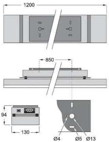
Cyclo 03 DMX HO and Cyclo 04 DMX HO
Contents
Introduction 4 Safety information 4
Installation....6 AC power....7 Data linking multiple luminaires....9 Connecting a DMX control device....10 Burning in new tubes....10
Stand-alone operation....11 DIP-switch settings in stand-alone mode....12 Stand-alone operation settings....13 Single stand-alone operation....14 host/client stand-alone operation....14
DMX controlled operation....18 Setting the luminaire to DMX operation....18 Controlling via DMX....21
Service....22 Fluorescent tube replacement....22 Cleaning....23
Troubleshooting ..... 24 DMX protocols ..... 25 Cyclo DMX HO Specifications ..... 26
Introduction
Thank you for selecting the Martin Cyclo DMX HO. This dynamic color-changing luminaire can be programmed with a stand-alone light show (which it can run alone or in a synchronized group), and is also DMX-controllable. The luminaire is designed to be used for cove and perimeter lighting, light walls, behind semi-transparent materials, or in any place where space is restricted.
The Martin Cyclo DMX HO features:
• Full 0-100% intensity control of all tubes, allowing RGB color mixing and color temperature correction.
• High output 54 W T5 fluorescent tubes.
- Long tube life of 20,000 hours.
- Through-wired power and control data cables for easy installation.
This manual covers two models rated 230V, 50/60Hz:
• The Cyclo 03 DMX HO, with red, green and blue tubes.
• The Cyclo 04 DMX HO, with red, green, blue and white tubes.
Important! Read this manual before you attempt to install this product.
Updated user manuals for this and all other Martin products are available from the Support area of the Martin Architectural website at http://www.martin-architectural.com.
Safety information
Warning! This product is for professional use only. It is not for household use.
This product present risks of lethal or severe injury due to fire and heat, electric shock and falls. Read this manual before powering or installing this luminaire, follow the safety precautions listed below and observe all warnings in this manual and on the luminaire. If you have any questions about how to operate this luminaire safely, please contact your Martin dealer
Protection from electric shock
- Disconnect the luminaire from AC power before removing or installing a tube, fuse, or any component and when not in use.
• Always ground (earth) the luminaire electrically. - Do not operate the luminaire if any cover or component is damaged, deformed or defective.
- Use only a source of AC power that complies with local building and electrical codes and has both overload and ground fault (earth fault) protection.
- Do not expose the luminaire to rain or moisture.
- Refer all service not described in this manual to a Martin service technician.
Protection from burns and fire
- Provide a minimum clearance of 0.1 meters (4 inches) around the luminaire.
- Never place filters or other materials over the clear polycarbonate cover.
- The exterior of the luminaire can become hot to the touch. Allow the luminaire to cool for at least 5 minutes before handling.
- Do not modify the luminaire or install other than genuine Martin parts.
- Do not operate the luminaire if the ambient temperature (Ta) exceeds 40irc C (104ircF) .
Protection from injury due to falls
- Ensure that all external covers, fasteners and components are secure.
- Ensure that all supporting structures, surfaces and fasteners can bear the weight of all devices installed.
- Block access below the work area whenever installing, servicing or removing the luminaire.
Installation
This section describes in general terms how to install the luminaire and connect it to power and control. These procedures must be performed by qualified professionals.

DMX control device
To ensure adequate ventilation, install the Cyclo DMX HO with a minimum of 25 mm (1 inch) of free space on each side.
To mount the luminaire:
- Loosen the two screws (see solid arrow in illustration) holding the mounting plate to the luminaire
- Remove the mounting plate from the luminaire.
- Fasten the mounting plate to the mounting surface using four 4 mm (1/6th in) diameter mounting screws or

natural_image
Isometric diagram of a device with arrows indicating movement or force, no text or symbols presentbolts that can bear the weight of the luminaire
AC power
It is the installer's responsibility to ensure that all local safety regulations and legal requirements are observed when installing and powering the Cyclo DMX HO.
AC mains power compatibility and consumption data are given in *Cyclo DMX HO Specifications* on page 26.
Many fixed installations use common neutral conductors in branch circuit distribution boxes. To avoid unintentional tripping of the RCD (ground fault circuit breaker), ensure that the Cyclo DMX HO's neutral conductor is connected to AC power via the same RCD as the live conductor.
Important! Cyclo DMX HO luminaires contain electronic ballasts that "leak" a total current of between 0.8mA and 4mA to ground (earth). Make sure that luminaires are correctly connected to ground (earthed) so that this "leakage" current can be absorbed.
Because of the "leakage" current, we recommend connecting a maximum of seven Cyclo DMX HO luminaires per circuit where each circuit is protected by a 30mA RCD. This should avoid unintentional tripping of RCDs. Bear in mind that some RCDs rated at 30mA may trip when leakage to ground is as low as 20mA.
Depending on the type of installation, electrical regulations in some countries may permit the use of RCDs with a trip current rating higher than 30mA. When considering this option, the installer must ensure that all local safety, building and electrical regulations are respected.
Connecting to power
Warning! Check that your local AC power voltage matches the voltage specified on the serial number label before applying power.
Calculate the total current draw of all devices to be connected and use a power cable with a suitable rating.
Cyclo DMX HO luminaires have an ENSTO male connector for AC power input built into the casing (see illustration). A female ENSTO cable connector is supplied with the luminaire for installation on your power cable.
You can power Cyclo DMX HO luminaires by wiring them in series. The internal wiring carries AC power through the luminaire from the power input to the power output connector.

natural_image
Illustration of a rectangular electronic device with two small windows and a display panel (no text or symbols)Power Input (male ENSTO connector)
Some common color-coding systems for AC power wiring are given below:
| Wire (EU) Wire (US) Pin Marking | |||
| brown black live "L" or "1" | |||
| blue white neutral "N" | |||
| yellow/green | green | ground | ± |
When installing the female ENSTO cable connector on the power cable, note the markings next to the screw terminals;
- The terminal marked 1 must be connected to the live wire.
• The terminal marked must be connected to the ground (earth) wire. - The terminal marked N must be connected the neutral wire.
The following connectors and cables are available from your Martin dealer:

ENSTO 3-pole 16A/250V male connector.... P/N 05347202
Data linking multiple luminaires
You need to create a serial data link to:
- Operate two or more Cyclo DMX HOs in host/client stand-alone mode, where all luminaires run a synchronized light show without a separate DMX control device
• Control luminaires with a DMX control device.
Luminaires on a serial data link must be daisy-chained in one single line, maximum 500 meters (1640 ft.) long, with maximum 32 luminaires. To exceed 32 luminaires or 500 meters, or to add branches, use an optically isolated amplifier-splitter such as the Martin RS-485 Opto-Splitter (P/N 90758060).
A reliable data connection requires suitable cable. CAT 5 (category 5) UTP (unshielded twisted pair) network cable is suitable for this purpose. Recommended minimum wire sizes are 0.25mm2 (24 AWG) for runs up to 300 meters (1000 ft.) and 0.34mm2 (22 AWG) for longer cable runs. Your Martin Architectural dealer can advise and supply suitable cable.
The: RJ-45 sockets in the Cyclo DMX HO are wired as follows: pins 7 & 8 to ground, pin 2 to signal - (cold), and pin 1 to signal + (hot).
Data connections are through-wired in the luminaire, so it is not important which RJ-45 socket is used for input and which for output.
To connect the data link:

flowchart
graph TD
    A["DMX controller"] --> B["DMX control link"]
    B --> C["Termination plug"]
    C --> D["DMX control link"]

- Terminate the link by inserting a an RJ-45 DMX termination plug (P/N 91613028) in the RJ-45 data output of the last luminaire.
Random "flicker" and other unexplained control problems during stand-alone host/client operation can often be cured by inserting an RJ-45 DMX termination plug into the unused socket of the first luminaire.
Connecting a DMX control device
If using a DMX control device, use suitable cable to connect the controller's DMX output to an RJ-45 socket on the first Cyclo DMX HO. If your control device has an XLR data output socket, you will need a male XLR-to-RJ45 converter, available from your Martin Architectural dealer (P/N 11840087).
For details of data link wiring and polarity, see "Data linking multiple luminaires" on page 9.
Burning in new tubes
For optimum tube life and performance, burn in new fluorescent tubes by running them for 100 hours at full power.
Stand-alone operation
In stand-alone operation, the Cyclo DMX HO can be used without a DMX controller. Static single colors or two-color mixes can be displayed, or luminaires can be programmed to change colors in cycles. Changes can be programmed at 1, 5, 10 or 30 second intervals.
Two stand-alone operation modes are available:
- In single stand-alone operation, luminaires run independently of each other. No data link is required.
- In clientluminaires must be linked. Synchronized action in all luminaires is triggered by one "host luminaire.
Programming single and host/client stand-alone operation involves setting the pins on the luminaire's DIP switch. The DIP switch is protected behind a sliding cover on the side of the power/control module housing. To access the switch, loosen the cover screw but do not remove it completely, then slide open the cover (see illustration).

natural_image
Diagram showing a mechanical component with an inset magnified view of a layered structure (no text or symbols)An overview of the DIP switch settings is provided on the next page. A quick reference table covering DIP switch functions is also provided on the back cover of this manual.
DIP-switch settings in stand-alone mode
Cyclo DMX HO 03
Pin Function
| 1 Red active |
| 2 Green active |
| 3 Blue active |
| 4 Not used |
5 & 6 Program speed
| Pin 6 Pin 5 Speed | |||
| OFF OFF 1 sec. steps (fastest setting) | |||
| OFF ON 5 sec. steps | |||
| ON OFF 10 sec. steps | |||
| ON ON 30 sec. steps (slowest setting) | |||
| 7 OFF = | Blackout fading, ON = Crossfading | ||
| 8 OFF = | Run program, ON = Pause program | ||
| 9 | OFF - host, ON - client (Note: do not set more than one luminaire as host) | ||
| 10 ON = | Stand-alone mode. | ||
Cyclo DMX HO 04
Pin Function
| 1 White active | |||
| 2 Red active | |||
| 3 Green active | |||
| 4 Blue active | |||
| 5 & 6 Program speed | |||
| Pin 6 Pin 5 Speed | |||
| OFF OFF 1 sec. steps (fastest setting) | |||
| OFF ON 5 sec. steps | |||
| ON OFF 10 sec. steps | |||
| ON ON 30 sec. steps (slowest setting) | |||
| 7 OFF = | Blackout fading, ON = Crossfading | ||
| 8 OFF = | Run program, ON = Pause program | ||
- OFF - host OM - client /Mota: do not not more than one luminaire no host
Stand-alone operation settings
Activating colors
DIP switch pins 1 to 3 (1 to 4 in Cyclo DMX HO 04 models) each activate a color in the stand-alone program.
Setting program speed
Combinations of DIP switch pins 5 and 6 allow one of four different speeds to be set.
Fading between colors
If DIP switch 7 is set to OFF (blackout fading), colors fade to almost blackout before the next color fades in.
If DIP switch 7 is set to ON (crossfading), color fading overlaps. If two or more colors are active, one color fades in while another is fading out, giving a color mixing effect. For example, if red and blue are activated and crossfading is selected, colors will crossfade from red through purple to blue, then back through purple to red in a continuous cycle (see example).
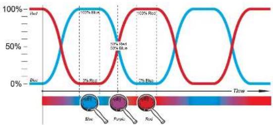
line
| Time | Red (%) | Blue (%) | |------|---------|----------| | 0 | 100 | 0 | | 100 | 0 | 100 | | 200 | 100 | 0 | | 300 | 0 | 100 | | 400 | 100 | 0 |Example: crossfading between red and blue
Setting a static color display
To set a static color display:
- Activate the color you wish to display (if you wish to display a two-color mix, activate these two colors) on DIP switch pins 1 to 3 (1 to 4 on 04 models).
- Set the luminaire as host by setting DIP switch pin 9 to OFF.
- Set DIP switch pins 5 and 6 to ON to activate the slowest program speed.
- Set DIP switch pin 7 to OFF to activate crossfading and DIP switch pin 8 to OFF to activate the program.
- When the desired color or color mix appears, pause the program by moving DIP switch 8 to ON. This color will remain "frozen" until DIP switch 8 is moved to OFF.
Note that the paused color is lost when the luminaire is powered off. When powering the luminaire on again, DIP switch pin 8 must be moved to OFF before the program will start.
Single stand-alone operation
In single stand-alone operation, a luminaire runs its own program independently of all other luminaires. To do this, the luminaire must be set as a host.
Activating single stand-alone operation
To activate single stand-alone operation:
- Set DIP switch pin 10 to ON (activates stand-alone mode).
- Set DIP switch pin 9 to OFF (activates host mode).
- Apply power and program the luminaire using DIP switch pins 1 - 8 (see "DIP-switch settings in stand-alone mode" on page 12).
client
Important!
Do not set more than one luminaire on a data link as host, and do not set a luminaire as host on a data link with a DMX controller. Doing so may cause damage to the electronics that is not covered by the product warranty.
identical on all luminaires, or luminaires can – subject to certain practical constraints – run programs that are synchronized but not identical.
Note that:
- Colors are always displayed in the order: red, green, then blue (white, red, green, then blue on 04 models). This means for example that if red is activated, it will always be first in the program. If red is not activated but green is activated, green will be first in the program.
• Each luminaire follows the program set on its own DIP switch as described in "DIP-switch settings in stand-alone mode" on page 12.
More sophisticated light shows can be programmed using a DMX controller (see "DMX controlled operation" on page 18).
The synchronization signal used by Cyclo DMX HO luminaires is identical to that used in other Cyclo luminaires with the same number of tubes, allowing these products to be combined in host/client operation on one data link. Luminaires that do not have the same number of tubes cannot be linked in host/client operation. Consult your Martin Architectural dealer if you need advice on combining and controlling products.
Identical light shows
host and client luminaires can be set to behave identically. In this mode, the host sends synchronizing signals to the clients, and all luminaires run the same light show. Each client luminaire follows the program set on its own DIP switch, so for identical operation, all luminaires' DIP switch settings must be the same apart from pin 9, which is set to ON for hosts and OFF for the host.
Synchronized non-identical light shows
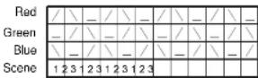
It is also possible to synchronize changes but program client luminaires to behave differently from the host. To use this feature effectively, you need to plan your light show using scenes as building blocks and set the luminaires' DIP switches accordingly.
A scene is a change from one output to another. When a luminaire is in client mode, it starts a scene when it receives a synchronization signal from the host. The time taken by the scene is determined by the speed setting of the client luminaire's DIP switch. A client will not respond to new synchronization signals until its scene is complete.
When crossfading is selected, each color takes up one scene (fade in only). When blackout fading is selected, each color takes up two scenes (fade in
Each time the host luminaire starts at scene 1, it sends a signal to all the client luminaires to start at scene 1. This means that if a client luminaire has:
- Fewer scenes than the host luminaire, it will run these in a cycle until the host luminaire signals that the program should start from the beginning again.
- More scenes than the host, the additional scenes will never run, because the program will reset to the first scene when the host starts its program from the beginning.
Here is an example of what will happen if a client luminaire has fewer scenes than the host luminaire:
Luminaire setting Scene pattern
| host with 6 scenes | 123456 | 123456 | 123456 | ... |
| client with 4 scenes | 123412 | 123412 | 123412 | ... |
Program examples
The following
examples show how
an individual
luminaire's program
is made up of
scenes.
The symbols on the
right are used in
program diagrams.

Tube turned fully off
Fade in
Fade out
Fade to 50% and back to 100% in one scene
Example 1
DIP switch 7 is set to ON (crossfading) and only red is activated:

Example 2
DIP switch 7 is set to OFF (blackout fading) and only red is activated:

Example 3
DIP switch 7 is set to ON (crossfading) and red and blue are activated:

Example 4
DIP switch 7 is set to OFF (blackout fading) and red and blue are activated:

Example 5
To achieve a rainbow effect, activate red, green and blue and set DIP switch pin 7 to ON (crossfading).
client To activate host/client stand-alone operation:
- Power all luminaires off.
- Set all luminaires as hosts and put them into stand-alone mode by setting DIP switch pins 9 and 10 to ON.
- Decide which luminaire to use as host and set this luminaire's DIP switch pin 9 to OFF. Note that any luminaire can be set as host, but you will obtain the most reliable data signal by either setting the first luminaire on the link as host or using RJ-45 DMX termination plugs at both ends of the data link.
- When power is applied, client luminaires will go to the next scene in their program each time the host goes to its next scene. client luminaires will
DMX controlled operation
The Cyclo DMX HO may be operated with any USITT DMX (1990) lighting control device. This section describes how to operate the system with a controller. See also "Troubleshooting" on page 24.
Setting the luminaire to DMX operation
DMX operation is enabled by setting pin 10 on the luminaire's DIP switch to OFF. The DIP switch can be accessed by loosening the DIP-switch cover screw (do not remove it completely) and sliding open the cover (see illustration.)

natural_image
Diagram of a mechanical component with an inset showing a magnified view of a section (no text or symbols present)Setting a DMX control address
The Cyclo DMX HO 03 uses 3 DMX control channels, and the Cyclo DMX HO 04 uses 4 DMX control channels.
The DMX address, also known as the start channel, is the first of these channels. It must be set on the luminaire and selected on the DMX controller before the controller can send commands to the luminaire via a DMX link.
The Cyclo DMX HO responds to commands sent to the DMX address and the channels immediately above it. This means that if the DMX address is set to 101:
T1 0 1 BIVUQ 25 1 1 401 400 1400
If two or more Cyclo DMX HOs share the same DMX address, they will receive the same commands and respond identically. Individual control will be impossible.
The default factory-set control address is '1'.
To set the Cyclo DMX HO's DMX address:
- Set DIP switch pin 10 to OFF to enable DMX operation.
- Decide on a DMX address for the luminaire. If you are calculating the DMX addresses for multiple luminaires, save time by using the online Martin Address Calculator at http://www.martin.dk/service/utilities/AddrCalc/index.asp (see example).
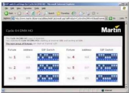
- You can also look up DIP-switch settings using the Martin DIP Switch Calculator, available for online use and download at http://www.martin.dk/service/dipswitchpopup.htm

To use this table, first find the DMX address in the main block in the table. Then read the settings for pins 1 - 5 to the left and read the settings for pins 6 - 9 above the address. "0" means OFF and "1" means ON.
For example, to set the DMX address to 101, you need to set DIP-switch pins 1, 3, 6 and 7 to ON, as highlighted in the table.
| DIP switch pins setting0 = OFF1 = ON | #90/00 0/001 1/111 1 | |||||||||||||||||
| #90/00 1/110 0/011 11 | ||||||||||||||||||
| #70/11 0/110 1/100 11 | ||||||||||||||||||
| #60/01 0/100 0/0101 1 | ||||||||||||||||||
| #1#2#3#4#5 | ||||||||||||||||||
| 00/00/326496128160/1922242562683320335384416478480 | ||||||||||||||||||
| 100/00/33659712916119322525728321355834174349421 | ||||||||||||||||||
| 0 | 1 | 0 | 0 | 0 | 2 | 34 | 66 | 98 | 130 | 162 | 194 | 226 | 258 | 290 | 322 | 354 | 386 | 418 |
| 110/00/3367969131163193227259231323355367419451483 | ||||||||||||||||||
| 00/10/0436681013216419622826029232356538420452164 | ||||||||||||||||||
| 1 | 0 | 1 | 0 | 0 | 5 | 37 | 69 | 101 | 133 | 165 | 197 | 229 | 261 | 293 | 325 | 357 | 389 | 421 |
| 01/10/06387011213416619623026228432358330422454486 | ||||||||||||||||||
| 111/00/37871113135167199231265295323593391424554587 | ||||||||||||||||||
| 0 | 0 | 0 | 1 | 0 | 8 | 40 | 72 | 104 | 136 | 168 | 200 | 232 | 264 | 296 | 328 | 360 | 392 | 424 |
| 100/1094773165137169201233265297329361393425457489 | ||||||||||||||||||
| 01/10/1042740613817020223426623636306239426458490 | ||||||||||||||||||
| 1 | 1 | 0 | 1 | 0 | 11 | 43 | 75 | 137 | 139 | 171 | 203 | 235 | 267 | 299 | 331 | 363 | 395 | 427 |
| 00/10/12447608140172204236283003936439628463492 | ||||||||||||||||||
| 10/11/1034577051411732053272635013336539729461493 | ||||||||||||||||||
| 0 | 1 | 1 | 1 | 0 | 14 | 46 | 78 | 110 | 142 | 174 | 206 | 238 | 270 | 302 | 334 | 366 | 398 | 430 |
| 1 | 1 | 1 | 1 | 0 | 15 | 47 | 79 | 111 | 143 | 175 | 207 | 239 | 271 | 303 | 335 | 367 | 399 | 431 |
| 00/00/1164880121441762082402723043653640032464496 | ||||||||||||||||||
| 1 | 0 | 0 | 0 | 1 | 17 | 49 | 81 | 113 | 145 | 177 | 209 | 241 | 273 | 305 | 337 | 369 | 401 | 433 |
| 01/00/11850821414617821024227430638375040234466498 | ||||||||||||||||||
| 110/00/11951831514717921124327530739371403354567499 | ||||||||||||||||||
| 0 | 0 | 1 | 0 | 1 | 20 | 52 | 84 | 116 | 148 | 180 | 212 | 244 | 276 | 306 | 340 | 372 | 404 | 436 |
| 10/10/1213585171491812132452773099137340537466G01 | ||||||||||||||||||
| 01/10/1225486181501821424627851039237440636470502 | ||||||||||||||||||
| 1 | 1 | 1 | 0 | 1 | 23 | 55 | 87 | 119 | 151 | 183 | 215 | 247 | 279 | 311 | 343 | 375 | 407 | 439 |
| 00/00/124568820152184216242630123437640840472634 | ||||||||||||||||||
| 100/11255789211513851217429261815335377409441479505 | ||||||||||||||||||
| 0 | 1 | 0 | 1 | 1 | 26 | 58 | 90 | 122 | 154 | 186 | 218 | 250 | 282 | 314 | 346 | 376 | 410 | 442 |
| 1 | 1 | 0 | 1 | 1 | 27 | 59 | 91 | 123 | 155 | 187 | 219 | 251 | 283 | 315 | 347 | 379 | 411 | 443 |
| 00/11/1285092241561862025228431638380412444745638 | ||||||||||||||||||
| 1 | 0 | 1 | 1 | 1 | 29 | 61 | 93 | 125 | 157 | 189 | 221 | 253 | 285 | 317 | 349 | 381 | 413 | 445 |
| 01/11/13062942815919022252426631638303241446478510 | ||||||||||||||||||
| 11/11/131365627159191223252526751938341547479511 | ||||||||||||||||||
Table 1: DMX address DIP-switch settings
Controlling via DMX
The Cyclo DMX HO's advanced fluorescent tubes can be dimmed from maximum output right down to zero on a DMX controller using one channel per tube. This allows a wide range of color shades with almost infinitely variable intensity to be obtained using additive color mixing. The color temperature of white light can be fine-tuned by running the white tube at high power and adding blue or red at low power. Replacement white tubes with various color temperatures are also available (see "Accessories" on page 27).
Depending on the functions available on the controller, sophisticated light shows on the Cyclo DMX HO can be programmed over time, allowing constantly and rapidly shifting color mixes, or color displays which change slowly according to the time of day, or even year, for example. See your DMX controller manual for details.
Your Martin Architectural dealer can advise about available controllers and control options.
Service
With long-life fluorescent tubes and virtually no moving parts, the Cyclo DMX HO is almost service-free.
Fluorescent tube replacement
The Osram high output T5 tubes fitted as standard meet color specifications for at least 10 000 hours. Average tube life is 20 000 hours, but note that tube life will vary depending on operating conditions.
To change a tube:
- Isolate the luminaire from the power supply and ensure that power cannot be reapplied, even accidentally.
- Ensure that the luminaire is securely mounted and block access below the work area before beginning any servicing work.
- Remove the two retaining screws and remove the front cover.

natural_image
Diagram showing a mechanical assembly with an upward arrow and a base component (no text or symbols)-
Pressing on the metal caps at both ends of the tube, rotate the tube 1/4 turn in whichever direction is easiest, and slide the tube's terminal pins out of their sockets. Support the tube at both ends as it is released.
-
To install a new tube, line it up so that the manufacturer's markings on all tubes are at the same end of the luminaire. Slide the tube's terminal pins fully into their sockets and rotate the tube 1/4 turn to engage the pins.
-
Reinstall the front cover before reapplying power.
Identifying tube positions
Tube positions are identified in the Cyclo DMX HO as follows:
| Marking in luminaire Marking | on tube Color Reference illustration |
| R OSRAM 54/60 Red | ||
| G OSRAM 54/66 Green | ||
| B OSRAM 54/67 Blue | ||
| No marking(Cyclo DMX HO04 only) | OSRAM 54/827OSRAM 54/840OSRAM 54/860 | 2700K white4000K white6000K white |
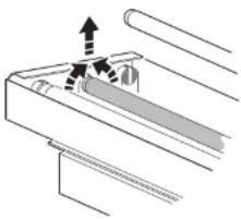
natural_image
Pure mechanical assembly diagram showing a lever mechanism with no text or symbolsTube removal (03 model illustrated)
The burning positions of fluorescent tubes affect their warm-up times, operating temperature, light output and tube life. For best results:
- Install tubes so that the manufacturer's markings are all at the same end of the luminaire.
- If the luminaire is installed in a vertical position or at an angle from the horizontal, locate the ends of the tubes that carry the manufacturer's markings at the lower end of the luminaire (in a cold environment, i.e. where temperatures are generally around or below freezing point, locate the markings at the upper end of the luminaire).
Troubleshooting
| Problem Probable cause(s) Remedy | ||
| No response from luminaire when power is applied. | No power to luminaire. Check power connections. | |
| Ground fault protection circuit breaker (RCD) has tripped. | Reset RCD. If problem persists, have an electrician replace the RCD or reduce the number of luminaires powered via one RCD. | |
| Luminaire does not respond correctly to DMX control. | Controller not connected. Check DMX data link. Inspect connections and test cables. Repair or replace as necessary. | |
| Incorrect DMX addressing. Check address setting on luminaire and controller. | ||
| Data link not terminated. Insert DMX termination plug in unused socket of last luminaire on data link. | ||
| Luminaire on link set as host. | Check that all luminaires are set as hosts (DIP switch pin 9 ON). | |
| Defective luminaire. Bypass luminaires one at a time until normal operation is regained. | ||
| Luminaires do not behave correctly in host/rollent mode | Two luminaires operating as masters. | Check that only one luminaire is set as host. |
| Data link not terminated. Insert DMX termination plug in unused socket of last luminaire on data link. If problem persists, insert DMX termination plug in unused socket of first luminaire on data link. | ||
| Defective luminaire. Bypass luminaires one at a time until normal operation is regained. | ||
| Poor quality light output and/or color rendering. | Tube or tubes not burnt in. Run luminaire for at least 100 hours to burn in tubes. | |
| Tube defective. Disconnect luminaire and replace tube. | ||
DMX protocols
Cyclo 03 DMX HO protocol
Start code = 0
| Channel Value Percent Function | |||
| 1 | Rod Intensity | ||
| 0-2 | 0 | Tube off | |
| 3-252 | 1 - 99 | Intensity 1→100% | |
| 253-255 | 100 | Intensity 100% | |
| 2 | Green Intensity | ||
| 0-2 | 0 | Tube off | |
| 3-252 | 1 - 99 | Intensity 1→100% | |
| 253-255 | 100 | Intensity 100% | |
| 3 | Blue Intensity | ||
| 0-2 | 0 | Tube off | |
| 3-252 | 1 - 99 | Intensity 1→100% | |
| 253-255 | 100 | Intensity 100% | |
Cyclo 04 DMX HO protocol
Start code = 0
| Channel Value Percent Function | |||
| 1(not used for Cyclo 03 DMX) | 0-23-252253-255 | 01 - 99100 | White intensityTube offIntensity 1→100%Intensity 100% |
| 2 | 0-23-252253-255 | 01 - 99100 | Red IntensityTube offIntensity 1→100%Intensity 100% |
| 3 | 0-23-252253-255 | 01 - 99100 | Green IntensityTube offIntensity 1→100%Intensity 100% |
| 4 | 0-2 | 0 | Blue IntensityTube off |
Cyclo DMX HO Specifications
PHYSICAL
L x W x H 1200 x 130x 94 mm (47.2 x 5.1 x 3.7 in.)
Finish . . . . . . . . . . . . . . . . . . . . . . . . . . . . . . . . . . . . . . . . . . . . . . . . . . . . . . . . . . . . . . . . . . . . . . . . . . . . . . . . . . . electrostatic powder coated, gray
Cyclo 03 DMX HO
Weight. 8.8 kg (19.4 lbs)
Cyclo 04 DMX HO
Weight. 10.5 kg (23.1 lbs)
SOURCE
Approved lamp type ..... OSRAM T5 HO 54 W fluorescent tubes
Expected lamp life....20 000 hours
DYNAMIC EFFECTS
Dimmable tubes .... red, green & blue (03 models)
red, green, blue & white (04 models)
Independent dimming of each tube via DMX control device
CONTROL AND PROGRAMMING
Control options ...... DMX 512, stand alone, host/client
Receiver....RS-485, 1 unit load
Setting and addressing ....DIP switch
Data input RJ-45
Data output RJ-45
DMX channels (Cyclo 03 HO DMX) 3
DMX channels (Cyclo 04 HO DMX) 4
INSTALLATION
Orientation any
Minimum free space around luminaire when installed . . . . 25 mm (1 inch)
POWER
AC power 198 - 250 V, 50 / 60 Hz
EnstoNet Installation System connectors
Typical power and current
Cyclo 03 DMX HO @ 230 V / 50 Hz 0.80 A,181 W
Cyclo 04 DMX HO @ 230 V / 50 Hz 1.02 A 234 W
THERMAL
Maximum ambient temperature ( Ta ) 40°C (104°F)
Minimum ambient temperature ( Ta ), started at full power... -20°C (-4°F)
Cooling . . . . . . . . . . . . . . . . . . . . . . . . . . . . . . . . . . convection
LISTINGS & APPROVALS

CE approved
INCLUDED ITEMS
Tube (installed, all models)....OSRAM T5 FQ 54W/60 (red)
Tube (installed, all models) ..... OSRAM T5 FQ 54W/66 (green)
Tube (installed, all models) ..... OSRAM T5 FQ 54W/67 (blue)
Tube (installed, 04 model only) . . . OSRAM T5 FQ 54W/840 (cool white)
User manual
ACCESSORIES
Diffuser front for Cyclo 04....P/N 91611078
Diffuser front for Cyclo 03....P/N 91611077
Warm white tube (2700 K, Osram T5 FQ 54W/827). . . . . . P/N 97020009
Daylight white tube (6000 K, Osram T5 FQ 54W/860) .....P/N 97020011
ENSTO 3-pole 16A/250V male connector .....P/N 05347202
ENSTO 3-pole 16A/250V female connector....P/N 05327202
ENSTO Male/female power cable (15 cm/5.9in.) .....P/N 11501019
RJ-45 data link termination plug . . . . . . . . . . . . . . . . . . . . . . . . . . . . . . . . . . P/N 91613028
3-pin XLR female to RJ-45 converter....P/N 11840086
3-pin XLR male to RJ-45 converter....P/N 11840087
CAT5 patch cable, RJ-45, 250 mm (9.8 in.) P/N 11840088
CAT5 patch cables, RJ-45, 2 m (6.5 ft) x 50 pcs....P/N 91611044
CAT5 patch cables, RJ-45, 5 m (16.4 ft) x 30 pcs .....P/N 91611045
CAT5 patch cables, RJ-45, 10 m (32.8 ft) x 15 pcs ..... P/N 91611046
ORDERING INFORMATION
Cyclo 03 DMX HO, EU model....P/N 90550114
Cyclo 04 DMX HO, EU model....P/N 90550003


- Dimensions
- Contents
- Introduction
- Safety information
- Protection from electric shock
- Protection from burns and fire
- Protection from injury due to falls
- Installation
- AC power
- Data linking multiple luminaires
- Connecting a DMX control device
- Burning in new tubes
- Stand-alone operation
- DIP-switch settings in stand-alone mode
- Cyclo DMX HO 04
- Stand-alone operation settings
- Activating colors
- Setting program speed
- Fading between colors
- Setting a static color display
- Single stand-alone operation
- Activating single stand-alone operation
- client
- Identical light shows
- Synchronized non-identical light shows
- Program examples
- Example 1
- Example 2
- Example 3
- Example 4
- Example 5
- DMX controlled operation
- Setting the luminaire to DMX operation
- Setting a DMX control address
- Controlling via DMX
- Service
- Fluorescent tube replacement
- Identifying tube positions
- DMX protocols
- Cyclo DMX HO Specifications
- PHYSICAL
- Cyclo 03 DMX HO
- Cyclo 04 DMX HO
- SOURCE
- DYNAMIC EFFECTS
- CONTROL AND PROGRAMMING
- POWER
- Typical power and current
- THERMAL
- LISTINGS & APPROVALS
- INCLUDED ITEMS
- ACCESSORIES
- ORDERING INFORMATION
Brand : MARTIN
Model : Cyclo DMX HO
Category : Lighting