
Cyclo IP65 US - Lighting MARTIN - Free user manual and instructions
Find the device manual for free Cyclo IP65 US MARTIN in PDF.

| Product Type | Dynamic fluorescent tube-based color-changing luminaire |
| Model | Cyclo IP65 US |
| Brand | Martin |
| Dimensions (L x W x H) | 1276 mm × 170 mm × 125 mm (50.3 × 6.7 × 4.9 in) |
| Weight | 7 kg (15.4 lbs) |
| Lamp Type | 54 W Osram T5 fluorescent tubes (RGB) |
| Color Mixing | RGB additive color mixing |
| Control Options | DMX, stand-alone, master/slave |
| DMX Channels | 3 |
| DMX Address Setting | DIP switch (pins 1-9) |
| AC Power | 100-120 V, 50/60 Hz |
| Power Consumption | 163 W at 100 V, 180 W at 120 V |
| Main Fuse | 2 AT (slow blow) |
| Protection Rating | IP65 (dustproof, protected against low-pressure water jets) |
| Maximum Ambient Temperature | 40 °C (104 °F) |
| Minimum Ambient Temperature (with permanent power) | -20 °C (-4 °F) |
| Tube Life | 20,000 hours average; color guaranteed for 10,000 hours |
| Housing Material | Polyester-reinforced composite |
| Front Cover Material | Unbreakable polycarbonate |
| Installation Orientation | Any |
| Included Items | User manual, 3 Osram T5 tubes (installed), cable glands, blanking plugs, sealing washers |
| Safety Standards | UL 1573, CSA C22.2 No. 166, EN 60598-1, EN 60598-2 |
Frequently Asked Questions - Cyclo IP65 US MARTIN
User questions about Cyclo IP65 US MARTIN
0 question about this device. Answer the ones you know or ask your own.
Ask a new question about this device
Download the instructions for your Lighting in PDF format for free! Find your manual Cyclo IP65 US - MARTIN and take your electronic device back in hand. On this page are published all the documents necessary for the use of your device. Cyclo IP65 US by MARTIN.
USER MANUAL Cyclo IP65 US MARTIN
natural_image
Close-up of a transparent cylindrical heat exchanger or cooling unit with metallic fittings and connectors (no visible text or symbols)user manual
Dimensions
Measurements are in millimeters

Martin
©2008 Martin Professional™ A/S. Information subject to change without notice. Martin Professional A/S and all affiliated companies disclaim liability for any injury, damage, direct or indirect loss, consequential or economic loss or any other loss occasioned by the use of, inability
Contents
Product overview....4
Introduction 5
Safety Information 6
Installation 8
Included items 8
Disassembly for access during installation 9
Mounting 10
AC power 11
Linking luminaires for DMX and master-slave operation. 15
Reassembly after installation 20
Burning in fluorescent tubes 20
Avoiding condensation and humidity.... 20
Operation in extreme ambient temperatures.... 21
Stand-alone operation....22
Stand-alone operation settings 23
Single stand-alone operation 24
Master/slave stand-alone operation 24
DMX-controlled operation....28
DMX control functions 28
Service 29
Tube removal and replacement 29
Main fuse replacement 31
Cleaning 31
Troubleshooting 32
DMX protocol 33
Cyclo IP65 US™ Specifications 34
Product overview

A - Front cover
B-Tubes
C - Lamp module
Introduction
Thank you for selecting a luminaire from the Martin Architectural™ Cyclo IP65™ series. The Cyclo IP65 US™ is a dynamic, fluorescent tube-based color-changing luminaire that can be controlled via DMX or programmed to run stand-alone light shows, alone or in synchronized groups.
The Cyclo IP65 is designed for dynamic illumination of walls and surfaces using RGB color mixing. Its red, green and blue 54 watt dimmable T5 fluorescent tubes combine high efficiency, bright color and long lamp life.
Luminaires can be surface-mounted or mounted on an adjustable bracket (available as an accessory) that can be tilted through 90°.
The IP65 rating means that luminaires are dustproof and protected from splashes and low-pressure water jets, making them suitable for outdoor installation. A self-purging humidity valve eliminates condensation.
Luminaires can start and operate with tubes dimmed to 1% light output in ambient temperatures as low as -20° C ( -4° F).
Important! Read this manual before attempting to install this product!
The most recent version of this user manual is available from the Support area of http://www.martin-architectural.com
Safety Information

WARNING!
Read the safety precautions in this section before installing, powering, operating or servicing this product.
The following symbols are used to identify important safety information on the product and in this manual:

Warning!
Safety hazard. Risk of severe injury or death.

Warning! Hazardous voltage. Risk of ethal or severe electric shock.

Warning! Fire hazard.

Warning! Refer to user manual.

Warning! This product is not for household use.
Read this manual before operating the product, follow the safety precautions listed below, and observe all warnings in this manual and printed on the product. Use this product only as described in this manual and in accordance with local laws and regulations.
This product presents risks of lethal or severe injury due to fire and heat, electric shock and falls. Read this manual before powering or installing this luminaire, follow the safety precautions listed in this section, and observe all warnings in this manual and on the luminaire. If you have any questions

Preventing electric shocks
- Disconnect the luminaire from AC power before removing or installing a tube or any part, and when not in use.
• Always ground (earth) the luminaire electrically. - Use only a source of AC power that complies with local building and electrical codes and has both overload and ground (earth) fault protection.
- Do not operate the luminaire if any cover or component is cracked, deformed or damaged in any way.
- Refer all service not described in this manual to a Martin service technician.

Preventing burns and fire
- Provide a minimum clearance of 25 mm (1 inch) around the luminaire.
- Do not place filters or other materials over the polycarbonate front cover.
- Do not modify the luminaire or install other than genuine Martin parts.
- Do not operate the luminaire if the ambient temperature (T a ) exceeds 40° C (104° F).
- Do not attempt to bypass thermostatic switches or fuses.
- Replace fuses only with ones of the specified type and rating.

Preventing injuries
- Ensure that all components and installation fittings are securely fastened.
- Ensure that all supporting structures, surfaces and fasteners can bear the weight of all luminaires installed.
- Block access below the work area whenever installing, servicing or removing the luminaire.
Installation
This section describes in general terms how to install the luminaire, including how to connect it to power and control data cables, and how to set it up for DMX control or stand-alone operation. These procedures must be performed by qualified professionals.
Luminaires have to be opened and the lamp module removed during installation, so it will save time if you carry out all the following tasks on each luminaire in one operation:
- Mounting the luminaire.
- Connecting power cables.
- Connecting DMX control data cables
- Setting DMX addresses or stand-alone programs on DMX models.
We recommend that you read the Installation section of this manual and familiarize yourself with the procedures involved before starting to install luminaires. If you are not familiar with DMX, pay particular attention to the section on setting DMX addresses.
Included items
Cyclo IP65 luminaires are supplied with the following items:
• 54 W Osram T5 fluorescent tubes (installed)
- 2 x M25 metal IP68 cable glands for AC power cable entry (designed to accept cable ∅ 8-12 mm / ∅ 0.31-0.47 in.)
- 2 x M16 metal IP68 cable glands for control cable entry
(designed to accept cable ∅ 7-10 mm / ∅ 0.28-0.39 in.)
- 2 x M25 metal blanking plugs for power cable entry holes
- 2 x M16 metal blanking plugs for control cable entry holes
- 2 x rubber sealing washers for mounting screws
Cable glands
cable in an existing installation is replaced with cable of a different diameter. Replacement glands must have the following characteristics:
Temperature range: -20° to +70°C (-4° to +158°F) or better
Ingress protection rating: IP 67 or 68
Power cable gland thread size: M25
Data cable gland thread size: M16
Minimum entry thread length: 10 mm (0.4 in.)
Disassembly for access during installation
Before it can be installed, the Cyclo IP65 must be partly disassembled for access to mounting points and electrical connections. To disassemble:
- Refer to "Product overview" on page 4. Undo the front cover retaining clips (F) and remove the front cover (A) from the luminaire as illustrated below.

natural_image
Three-step diagram showing a mechanical component with arrows indicating motion, no text or symbols present- Remove one or more tubes (see "Tube removal and replacement" on page 29) to give access to the lamp module retaining screws (D) in the reflector tray.
- Remove the two lamp module retaining screws to release the lamp module (C), and lift the lamp module clear of the housing (E). The lamp module is attached to the housing by retaining straps.
Mounting
The Cyclo IP65 can be surface-mounted on a floor, wall or ceiling. The user must supply fasteners (bolts or screws) and sealing washers (rubber or similar flexible material) that are suitable for the application and mounting surface.
To mount the Cyclo IP65:
- Ensure that the mounting surface is flat and can support the weight of all the devices to be installed on it. Allow 25mm (1 inch) of free space around each luminaire.
- Drill holes in four of the eight 'feet' in the housing to take mounting fasteners. To help ensure a waterproof seal, ensure that holes are slightly smaller in diameter than the fasteners so that fasteners will be a tight fit in the housing.
- Mark up and drill holes for fasteners in the mounting surface.
- Fasten the luminaire to the surface by screwing four bolts or screws (grade 8.8 minimum) through the four holes in the luminaire housing, then through rubber sealing washers, and finally into the holes in the mounting surface. Check that there is a waterproof seal where fasteners enter the housing.
- Check that the luminaire housing is not distorted and is securely attached to the mounting surface before connecting cables (see following sections).
AC power
Warning! It is the installer's responsibility to ensure that all power cable and equipment is adequately dimensioned and of appropriate type for the installation, and that all local safety regulations and legal requirements are observed when installing and connecting the Cyclo IP65.
The Cyclo IP65 US accepts AC power at 100 - 120 V, 50 or 60 Hz. Do not operate the luminaire at any other voltage or frequency.
Current and power data are given in the Specifications section on page 34.
Inrush currents and electronic circuit-breakers
When fluorescent tubes with ECG (electronic control gear) systems are switched on at the AC wave peak, a larger current surge occurs than with conventional ballasts. If a large number of luminaires are switched on simultaneously, this inrush current can trip electronic circuit breakers. To avoid this in large installations, either switch on luminaires at intervals or limit the number of luminaires per 16 A electronic circuit breaker to approximately ten luminaires.
RCDs and common neutral conductors
Many fixed installations use common neutral conductors in branch circuit distribution boxes. To avoid unintentional tripping of the RCD (residual current device, or ground fault/earth leakage circuit breaker), ensure that each luminaire's neutral conductor is connected to AC power via the same RCD as the live conductor.
Leakage to ground and RCDs
Each ECG unit "leaks" a total current of maximum 0.5 mA to ground (earth). Luminaires must be correctly connected to ground so that this "leakage" current can be absorbed.
Allow for the "leakage" current from ECGs when connecting luminaires to a circuit that has an RCD for ground fault protection, otherwise the RCD may trip unintentionally. Bear in mind that RCDs are rated at their maximum trip current, and that some RCDs rated 30mA may trip when leakage to ground is as low as 20mA .
RCDs can also be tripped by the inrush current when tubes are switched on.
-
If it is both safe and legal, use RCDs with a trip current rating higher than 30 mA. When considering this option, the installer must ensure that all local building and electrical regulations are respected. Maximum legally permitted RCD trip current ratings are normally stated in national electrical and building codes.
-
Install surge current-resistant RCDs.
Connecting to power

natural_image
Cross-sectional diagram of a mechanical component with layered structure and labeled parts (no readable text or symbols)Power and data connectors
Self-purging humidity valve
Cable glands
Power cable must be adequately dimensioned and of appropriate type for the installation. Ensure that power cannot be applied to the cable during installation.
The Cyclo IP65 is supplied with two cable glands that must be used for power cable entry and exit.
Two clamp connectors are provided, one in each end of the casing, for connecting to power. Luminaires are through-wired, so it is not important which of the two connectors is used for power input and which for power output.
Some common color-coding systems for AC mains wiring are given below:
Wire (EU) Wire (US) Pin Marking
| brown black live "L" or "1" | |
| blue white neutral "N" | |
| yellow/green green ground | ⊥ |
- Ensure that power cannot be applied to the cables in the installation (by removing fuses at the distribution board, for example).
- If the front cover and lamp module have not been removed, remove them (see "Disassembly for access during installation" on page 9). Connection may be easiest with the lamp module hanging from its retaining straps.
- See Figure 1. Dismantle a power cable gland (the M25 power cable glands are larger than the M16 control cable glands).

- Ensure that there is a rubber seal B on the locking nut end of the cable entry C, and push this end through the hole provided in the luminaire housing so that the seal B faces the outer surface of the housing.
- Screw the locking nut A onto the cable entry from inside the housing. Prevent the cable entry from turning, and tighten the locking nut until the seal makes a water-resistant seal against the outer surface of the housing. Do not over-tighten, as this may damage the seal or housing.
- Thread the power input cable through the compression nut F, then washer E, gland D, and cable entry C into the luminaire housing.
-
Allow approx. 30 cm (12 in.) of cable slack inside the housing. Prevent the cable entry from turning and tightening the compression put sufficiently
-
Connect the power cable wires to the connectors marked 12 L, and N.
- Connect the terminal marked 12 to ground (earth).
- Connect the terminal marked N to neutral.
- Connect the terminal marked L to live.
- If power cable is to continue to another luminaire, repeat steps 2 to 7 for the power output cable.
For details of connecting control cables for DMX or master/slave operation, see "Linking luminaires for DMX and master-slave operation" on page 15.
For details of reassembling the luminaire after you have finished connecting cables, see "Reassembly after installation" on page 20.

Figure 2: Power connection
Linking luminaires for DMX and master-slave operation
You need to create a serial data link to:
• Control luminaires with a DMX control device.
- Operate two or more Cyclo IP65s in master/slave stand-alone mode, where all luminaires run a synchronized light show without a separate DMX control device.
A reliable data connection requires suitable cable. CAT 5 (category 5) UTP (unshielded twisted pair) network cable is suitable for this purpose. The minimum recommended wire size is 0.2 mm 2 (24 AWG) for runs up to 300 meters (1000 ft.) and 0.322 mm 2 (22 AWG) for runs up 500 meters (1640 ft.). Your Martin Architectural dealer can advise and supply suitable cable.
Luminaires on a serial data link must be daisy-chained in one single line, maximum 500 meters (1640 ft.) long, with maximum 32 luminaires. To exceed 32 luminaires or 500 meters, or to add branches, an optically isolated amplifier-splitter such as the Martin RS-485 Opto-Splitter (P/N 90758060) must be used.
A male 3-pin XLR connector can be fitted at the controller end of the data link to allow a standard connection to Martin DMX controller. The XLR connector should be wired as follows:
- Pin 1: shield
• Pin 2: DMX - (cold)
• Pin 3: DMX + (hot)
To avoid ground/earth loop interference, make sure the DMX cable shield does not come into contact with the shell or body of the XLR connector.
Two screw-type terminal blocks are provided, one in each end of the casing, for connecting to data. Luminaires are through-wired, so it is not important which of the two terminal blocks is used for data input and which for data output. However, the data output may only be used to relay data to one luminaire.
Connecting to control data


To create the data link:
- If using a DMX control device, run suitable cable from the controller's DMX output to the first luminaire on the link.
- Use an M16 cable gland to run the data cable through the luminaire housing (for instructions on installing cable glands, see "Connecting to power" on page 12).
- Connect the data cable wires to whichever of the two terminal blocks is most convenient. Wiring polarity is labelled on the luminaire.
- Continue connecting up to 32 luminaires using the above procedure.
- Terminate the data link by connecting a 120 Ohm, 0.25 W resistor across the + (hot) and - (cold) terminals of the last luminaire's terminal block.
Tlp! Random "flicker" and other unexplained control problems during stand-alone master/slave operation can often be cured by also connecting a 120 Ohm resistor across the + (hot) and - (cold) terminals of the first luminaire's data connection terminal block.
Configuring luminaires for DMX or stand-alone operation
Each DMX model Cyclo IP65 luminaire needs to be set up for DMX or stand-alone operation using the DIP switch located on the circuit board on the lamp module.

DIP switch
Configuring for DMX operation
DMX operation is enabled by setting pin 10 on the DIP switch to OFF. Pins 1 - 9 are then used to set the luminaire's control address.
The Cyclo IP65 uses one DMX channel to control each tube. The DMX address, also known as the start channel, is the first of these channels. It must be set on the luminaire (and selected on the DMX controller) before the controller can send commands to the luminaire via a data link. For example, a Cyclo IP65 with its DMX address set to 101 uses channels 101, 102 and 103 to control its three tubes.
Allow enough channels when setting the DMX address. If control channels for two fixtures overlap, one of the fixtures will receive the wrong commands.
If two or more Cyclo IP65s share the same DMX address, they will receive the same commands and respond identically. Individual control will be impossible.
To set the Cyclo IP65's DMX address:
-
Set DIP switch pin 10 to OFF.
-
Decide on a DMX address for the luminaire. If you are calculating the DMX addresses for multiple luminalres, save time by using the online Martin Address Calculator at http://www.martin.dk/service/utilities/AddrCalc/index.asp (see illustration below).

- You can also look up DIP switch settings using the Martin DIP Switch Calculator, available for use and downloadable at http://www.martin.dk/service/dipswitchpopup.htm If you do not have Internet access, refer to "Table 1: DMX address DIP switch settings" on page 19.

To use this table, first find the DMX address in the main block in the table. Then read the settings for pins 1 - 5 to the left and read the settings for pins 6 - 9 above the address. "0" means OFF and "1" means ON.
For example, to set the DMX address to 101, you need to set DIP switch pins 1, 3, 6 and 7 to ON, as highlighted in the table.
| DIP switch pins setting0 = OFF1 = ON | #90C00 0C001 11111 | ||||||||||||||||||
| #80C00 1110400111 | |||||||||||||||||||
| #70C11 0C11041C0011 | |||||||||||||||||||
| #60C01 0C1010C10111 | |||||||||||||||||||
| #1/#2/#3/#4/#5 | |||||||||||||||||||
| 0000032649612816 01922242652883203032364416448480 | 0000032649612816 01922242652883203032364416448480 | ||||||||||||||||||
| 100001336597129164198225257289232165385414349481 | |||||||||||||||||||
| 0 | 1 | 0 | 0 | 0 | 0 | 2 | 34 | 66 | 88 | 130 | 162 | 194 | 226 | 258 | 290 | 322 | 354 | 386 | 418 |
| 110003367599131163195227256291323855387415451483 | 110003367599131163195227256291323855387415451483 | ||||||||||||||||||
| 0010043668100132 04416226262602923235638420452484 | |||||||||||||||||||
| 1 | 0 | 1 | 0 | 0 | 0 | 5 | 37 | 69 | 101 | 133 | 165 | 197 | 229 | 261 | 293 | 325 | 357 | 388 | 421 |
| 0110063670102134 066188230262294323356389042454486 | 1110063670102134 066188230262294323356389042454486 | ||||||||||||||||||
| 1110073971103135 0671992312632632735890143455487 | 1110073971103135 0671992312632632735890143455487 | ||||||||||||||||||
| 0 | 0 | 0 | 1 | 0 | 0 | 8 | 40 | 72 | 104 | 136 | 168 | 200 | 232 | 264 | 296 | 328 | 360 | 392 | 424 |
| 1001094173105137 0692012332652973233611394342547489 | 1001094173105137 0692012332652973233611394342547489 | ||||||||||||||||||
| 0101013427410613 081702022342662683890362394126455490 | 0101013427410613 081702022342662683890362394126455490 | ||||||||||||||||||
| 1 | 1 | 0 | 1 | 0 | 0 | 11 | 43 | 75 | 107 | 139 | 171 | 203 | 235 | 267 | 299 | 331 | 363 | 395 | 427 |
| 001011244761081401720423626830032636-396-28460492 | 1001011244761081401720423626830032636-396-28460492 | ||||||||||||||||||
| 1010113457710914173205237269301383363397-294601493 | |||||||||||||||||||
| 0 | 1 | 1 | 1 | 0 | 0 | 14 | 46 | 78 | 110 | 142 | 174 | 206 | 238 | 270 | 302 | 334 | 366 | 398 | 430 |
| 1 | 1 | 1 | 1 | 0 | 0 | 15 | 47 | 79 | 111 | 143 | 175 | 207 | 239 | 271 | 303 | 335 | 367 | 399 | 431 |
| 00000116498011214 441762062402733043636440032464496 | |||||||||||||||||||
| 1 | 0 | 0 | 0 | 1 | 0 | 17 | 49 | 81 | 113 | 145 | 177 | 209 | 241 | 273 | 305 | 337 | 369 | 401 | 433 |
| 010001185082114146178210242274306383740243464698 | |||||||||||||||||||
| 1 | 1 | 0 | 0 | 1 | 0 | 19 | 51 | 83 | 115 | 147 | 179 | 211 | 243 | 275 | 307 | 339 | 371 | 403 | 435 |
| 0 | 0 | 1 | 0 | 1 | 0 | 20 | 52 | 84 | 116 | 148 | 180 | 212 | 244 | 276 | 308 | 340 | 372 | 404 | 436 |
| 101012153851714 491812132452773093 1373405537469501 | 101012153851714 491812132452773093 1373405537469501 | ||||||||||||||||||
| 011012254861815 50182142462783103237440638470502 | |||||||||||||||||||
| 1 | 1 | 1 | 0 | 1 | 0 | 23 | 55 | 87 | 119 | 151 | 183 | 215 | 247 | 279 | 311 | 343 | 375 | 407 | 439 |
| 00011245688120 521842162482801234376408-40472504 | 10011245688120 521842162482801234376408-40472504 | ||||||||||||||||||
| 100112557891215 5318521724928131335377409441478505 | |||||||||||||||||||
| 0 | 1 | 0 | 1 | 1 | 0 | 26 | 56 | 90 | 122 | 154 | 186 | 218 | 250 | 282 | 314 | 346 | 378 | 410 | 442 |
| 110112769911235 5518721825128331539737941143475507 | 110112769911235 5518721825128331539737941143475507 | ||||||||||||||||||
| 001112860921245 561882205228431698389041244476508 | |||||||||||||||||||
| 1 | 0 | 1 | 1 | 1 | 0 | 29 | 61 | 93 | 125 | 157 | 189 | 221 | 253 | 265 | 317 | 349 | 381 | 413 | 445 |
| 011113062941265 5819022254288318369036241446478510 | 111113062941265 5819022254288318369036241446478510 | ||||||||||||||||||
| 111113163951275 5819122325528731939138341547479511 | |||||||||||||||||||
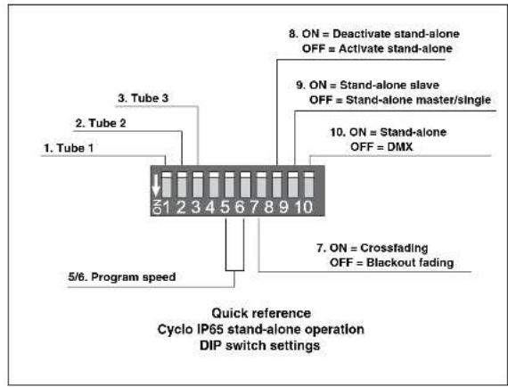
Configuring for stand-alone operation
Stand-alone operation is enabled by setting pin 10 on the DIP switch to ON and pin 8 to OFF. The other pins are then used to program the luminaire. See "Operation in extreme ambient temperatures" on page 21 for details of how to set these pins.
Reassembly after installation
To reassemble the luminaire after installing and configuring:
- Seal any holes that have not been used for cable entry with the blanking plugs and flat rubber seals supplied with the luminaire. These should be tight enough to make a waterproof seal, but do not over-tighten.
- Reinstall the lamp module in the housing, making sure that no wires are trapped.
- Reinstall any tubes that were removed. Colored tube positions are labelled R, G and B. Install tubes with their manufacturers' markings at the same end of the luminaire.
- Reinstall the front cover before applying power.
Burning in fluorescent tubes
Optimum tube performance is obtained after burning in new fluorescent tubes by running them for 100 hours at full power.
Avoiding condensation and humidity
Excess humidity inside the luminaire can be experienced if:
• The front cover is not correctly clipped onto its seal.
- Cable glands are not correctly assembled, tightened and matched to cable diameters
- Blanking plugs are not correctly fitted and tightened
The Cyclo IP65 is fitted with a self-purging valve that gradually expels moisture as the luminaire heats up and cools down in normal use. To eliminate condensation rapidly (after installation, for example), run the luminaire at full operating temperature in dry weather conditions for a minute or two with the front cover removed so that air circulates, then refit the front cover while the luminaire is hot. If you do this:
- The exposed lamp and internals present a risk:, so block public access.
- Ensure that no dust or objects enter the luminaire while it is open.
Operation in extreme ambient temperatures
Do not operate the Cyclo IP65 if the ambient temperature exceeds 40°C.
Cyclo IP65 luminaires can be operated in ambient temperatures as low as -20°C (-4°F) , but a combination of low temperature and low dimming level will give a risk of flickering and cause voltage across tubes to rise. In extreme cases, luminaires will shut down power to tubes to avoid damage to components. If this happens, luminaires must be reset by powering them off and on again before tubes can be restarted.
Flickering can be avoided at ambient temperatures below freezing point if luminaires are left powered on when not in use so that they generate their own heat and maintain tube temperature at or above freezing point. For best low-temperature dimming performance;
- As soon as the ambient temperature falls below 0°C (32°F), apply power permanently to luminaires. If light output is not required, reduce output by dimming tubes instead of shutting down power completely.
- If flickering occurs when dimming, increase the minimum dimming level.
- If flickering occurs when dimming luminaires after startup, start luminaires at full power for several minutes.
As a general rule, the higher the light output, the lower the ambient temperature luminaires can tolerate.
Stand-alone operation
In stand-alone operation, the Cyclo IP65 can run light shows without a DMX controller. Luminaires can be programmed to change colors in cycles. Changes can be programmed at 1, 5, 10 or 30 second intervals.
Two stand-alone operation modes are available:
- In single stand-alone operation, luminaires run independently of each other. No data link is required.
- In master/slave stand-alone operation, luminaires must be linked with a serial data link ("Linking luminaires for DMX and master-slave operation" on page 15 explains how to install this link). Synchronized action in all luminaires is triggered by one "master" luminaire.
In both single and master/slave stand-alone operation, luminaires are programmed by setting the pins on the DIP switch on the circuit board as shown in the following table:
Pin Function
| 1 Red active |
| 2 Green active |
| 3 Blue active |
| 4 Not used |
5 & 6 Program speed
| Pin 6 Pin 5 Speed | |||
| OFF OFF 1 sec. steps (fastest setting) | |||
| OFF ON 5 sec. steps | |||
| ON OFF 10 sec. steps | |||
| ON ON 30 sec. steps (slowest setting) | |||
| 7 OFF = Blackout fading, ON = Crossfading | |||
| 8 | OFF = Run program, ON = Deactivate program (Note: always set to OFF) | ||
| 9 | OFF = Master, ON = Slave (Note: do not set more than one luminaire as master) | ||
| 10 ON = Stand-alone mode. | |||
A quick reference table covering DIP switch functions is also provided on the back cover of this manual.
Stand-alone operation settings
Activating colors
DIP switch pins 1 to 3 activate tubes in the stand-alone program.
Setting program speed
Combinations of DIP switch pins 5 and 6 allow one of four different speeds to be set.
Fading between colors
If DIP switch pin 7 is set to OFF (blackout fading), colors fade to almost blackout before the next color fades in.
If DIP switch pin 7 is set to ON (crossfading), color fading overlaps. If two or more colors are active, one color fades in while another is fading out, giving a color mixing effect. For example, if red and blue are activated and crossfading is selected, colors will crossfade from red through purple to blue, then back through purple to red in a continuous cycle (see example).

line
| Time Segment | Value | | ------------ | ----- | | Red | 100% | | Blue | 0% | | Purple | 50% | | Blue | 50% | | Red | 100% | | Blue | 0% |Single stand-alone operation
In single stand-alone operation, a luminaire runs its own program independently of all other luminaires. To do this, the luminaire must be set as a master.
Activating single stand-alone operation
To activate single stand-alone operation:
-
Set DIP switch pin 10 to ON (switches from DMX to stand-alone mode).
-
Set DIP switch pin 9 to OFF (activates master mode).
-
Set DIP switch pin 8 to OFF (activates stand-alone mode)
-
Program the luminaire using DIP switch pins 1 - 7 (see Table 2 on page 22).
Master/slave stand-alone operation
Important!
Do not set more than one luminaire on a data link as master, and do not set a luminaire as master on a data link with a DMX controller. Doing so may cause damage to the electronics that is not covered by the product warranty.
In master/slave stand-alone operation, one master luminaire transmits a synchronizing signal to slave luminaires over the data link each time it starts a new action. Slave luminaires start their next programmed action when they receive this signal from the master luminaire. Programs can be identical on all luminaires, or luminaires can – subject to certain practical constraints – run programs that are synchronized but not identical.
Note that each luminaire follows the program set on its own DIP switch as described in Table 2 on page 22.
Note also that colors are always displayed in the order red → green → blue.
This means for example that if red is activated, it will always be first in the program. If red is not activated but green is activated, green will be
The synchronization signal used by the Cyclo IP65 is identical to that used in other Cyclo luminaires with the same number of tubes, allowing these products to be combined in master/slave operation on one data link. However, Cyclos with different numbers of tubes cannot be mixed in master-slave operation. Consult your Martin Architectural dealer if you need advice on combining and controlling products.
Identical light shows
Master and slave luminaires can be set to behave identically. In this mode, the master sends synchronizing signals to the slaves, and all luminaires run the same light show. Each slave luminaire follows the program set on its own DIP switch, so for identical operation, all luminaires' DIP switch settings must be the same apart from pin 9, which is set to ON for slaves and OFF for the master.
Synchronized non-identical light shows
It is also possible to synchronize changes but program slave luminaires to behave differently from the master. To use this feature effectively, you need to plan your light show using scenes as building blocks and set the luminaires' DIP switches accordingly.
A scene is a change from one output to another. When a luminaire is in slave mode, it starts a scene when it receives a synchronization signal from the master. The time taken by the scene is determined by the speed setting of the DIP switch. A slave will not respond to new synchronization signals until its scene is complete.
When crossfading is selected, each color takes up one scene (fade in only). When blackout fading is selected, each color takes up two scenes (fade in and fade out). This means that the maximum number of scenes that can be programmed is twice the number of tubes installed, with all tubes activated and blackout fading selected.
Each time the master luminaire starts at scene 1, it sends a signal to all the slave luminaires to start at scene 1. This means that if a slave luminaire has:
-
Fewer scenes than the master luminaire, it will run these in a cycle until the master luminaire signals that the program should start from the beginning again.
-
More scenes than the master, the additional scenes will never run, because the program will reset to the first scene when the master starts its program from the beginning.
Here is an example of what will happen when a slave luminaire has fewer scenes than the master luminaire:
Luminaire setting Scene pattern
Master with 6 scenes 123456 123456 123456..
Slave with 4 scenes 123412 123412 123412...
Program examples
The following examples of programs show how an individual luminaire's program is made up of scenes.
The following symbols are used in program diagrams:

Tube turned fully off
Fade in
Fade out
Fade to 50% and back to 100% in one scene (applies when only one color is active and crossfading is selected)
Example 1
DIP switch 7 is set to ON (crossfading) and only red is activated;

Example 2
DIP switch 7 is set to OFF (blackout fading) and only red is activated:

Example 3
DIP switch 7 is set to ON (crossfading) and red and blue are activated:

Example 4
DIP switch 7 is set to OFF (blackout fading) and red and blue are activated:

Example 5
To achieve a rainbow effect, activate red, green and blue tubes and set DIP switch pin 7 to ON (crossfading).

Activating master/slave stand-alone operation
To activate master/slave stand-alone operation:
- Isolate all luminaires from power.
- Set all luminaires as slaves and enable stand-alone mode by setting DIP switch pins 9 and 10 to ON and pin 8 to OFF.
- Decide which luminaire to use as master and set this luminaire's DIP switch pin 9 to OFF. Note that any luminaire can be set as master, but you will obtain the most reliable data signal by either setting the first luminaire on the link as master or using 120 Ohm resistors to terminate the data link (see "Connecting to control data" on page 16) at both ends.
DMX-controlled operation
Cyclo IP65 DMX models may be operated with any lighting control device that is compatible with the USITT DMX (1990) standard.
For details of connecting luminaires on a data link to a DMX controller, see "Linking luminaires for DMX and master-slave operation" on page 15.
For details of setting up luminaires for DMX control, see "Configuring luminaires for DMX or stand-alone operation" on page 17.
DMX control functions
The Cyclo IP65's advanced fluorescent tubes can be dimmed from maximum output right down to zero using one channel per tube on a DMX controller. This allows a wide range of color shades with variable intensity to be obtained using additive color mixing.
Depending on the functions available on the controller, sophisticated light shows on the Cyclo IP65 can be programmed over time, allowing constantly and rapidly shifting color mixes, or color displays which change slowly according to the time of day, or even year, for example. See the controller's manual for details.
Your Martin Architectural dealer can advise about available controllers and control options.
Service
With long-life fluorescent tubes and no moving parts, the Cyclo IP65 is almost service-free.
Tube removal and replacement
The Osram high output T5 tubes fitted as standard meet color specifications for at least 10 000 hours. Average tube life is 20 000 hours, but note that tube life will vary depending on operating conditions.
No tools are required to replace a fluorescent tube on the Cyclo IP65.
To remove tubes:
- Isolate the luminaire from power and ensure that power cannot be reapplied, even accidentally.
- Ensure that the luminaire is securely mounted and block access below the work area before beginning any servicing work.
- Remove the front cover retaining clips and remove the cover.

natural_image
Three-step diagram showing a mechanical component with a curved top, a dashed arrow indicating rotation, and an upward arrow highlighting the process (no text or symbols)Front cover removal
-
Holding the metal caps at both ends of the tube, rotate the tube 1/4 turn in whichever direction is easiest, and slide the tube's terminal pins out of their sockets. Support the tube at both ends as it is released.
-
To install a new tube, line it up so that the manufacturer's markings on all tubes are at the same end of the

natural_image
Diagram of a mechanical assembly with arrows indicating force or movement (no text or symbols)Tube removal
luminaire. Slide the tube's terminal pins fully into their sockets and rotate the tube 1/4 turn in any direction to engage the pins. Check that the tube is held securely in the sockets.
- Reinstall the front cover before reapplying power.
Tube positions
Tube positions are labelled R for red, G for green and B for blue.
The burning positions of fluorescent tubes affect their warm-up times, operating temperature, light output and tube life. For optimum results:
• Install tubes so that the manufacturer's markings are all at the same end of the luminaire.
- If the luminaire is installed in a vertical position or at an angle from the horizontal, locate the ends of the tubes that carry the manufacturer's markings at the lower end of the luminaire.
- In a cold environment, i.e. where temperatures are generally around or below freezing point, locate the markings at the upper end of the luminaire.
Main fuse replacement
The main fuse is located on the circuit board. See page 34 in the Specifications section for details of fuse types and ratings. Never replace a fuse with one of a different type or rating.

Always isolate luminaires from power and ensure that power cannot be reapplied accidentally before replacing fuses.
If a fuse blows repeatedly, refer to your Martin Architectural dealer for service.
Important: The PCB voltage selector switch next to the main fuse must be set to 110 V. Do not move it from this setting! The Cyclo IP65 US model accepts 100-120 V power only.
Cleaning
Use a damp cloth to wipe luminaires clean.
Do not use a high pressure water-jet for cleaning: IP65 luminaires are protected against splashing and low-pressure water iets only.
Troubleshooting
| Problem Probable cause(s) | Remedy | |
| No response from luminaire when power is applied. | If running in stand-alone mode, DIP switch pin 8 is set to ON. | Set DIP switch pin 8 to OFF to allow stand-alone operation. |
| No power to luminaire. Check power connections. | ||
| Ground fault protection circuit breaker (RCD) has tripped. | Reset RCD. If problem persists, have an electrician replace the HCD or reduce the number of luminaires powered via one RCD. | |
| Luminaires do not respond correctly to DMX control. | Controller not connected. | Check DMX data link. Inspect connections and test cables. Repair or replace as necessary. |
| Incorrect DMX addressing. | Check address setting on luminaire and controller. | |
| Data link not terminated. | Connect 120 Ohm termination resistor across data link + (hot) and - (cold) in parallel with last luminaire on link. | |
| Two devices transmitting on link. | Check that all luminaires are set as slaves (DIP switch pin 9 ON). | |
| Defective luminaire. | Bypass luminaires one at a time until normal operation is regained. | |
| Luminaires do not behave correctly in master/slave mode. | Two luminaires transmitting on link. | Check that only one luminaire is set to operate as master. |
| Defective luminaire. | Bypass luminaires one at a time until normal operation is regained. | |
| Poor quality light output and/or color rendering. | Tube or tubes not burnt in. | Burn in new tubes at full intensity for at least 100 hours to obtain correct performance. |
| Tube defective. | Disconnect luminaire and replace tube. | |
DMX protocol
Start code = 0
| Channel Value Percent Function | |||
| 1 | 0-2 | 0 | Red IntensityTube offIntensity 1→100%Intensity 100% |
| 3-252 | 1 - 99 | ||
| 253-255 | 100 | ||
| 2 | 0-2 | 0 | Green IntensityTube offIntensity 1→100%Intensity 100% |
| 3-252 | 1 - 99 | ||
| 253-255 | 100 | ||
| 3 | 0-2 | 0 | Blue IntensityTube offIntensity 1→100%Intensity 100% |
| 3-252 | 1 - 99 | ||
| 253-255 | 100 | ||
Table 3: DMX protocol
Cyclo IP65 US™ Specifications
Specifications subject to change
Physical
| Length | 1276 mm (50.3 in.) |
| Width | 170 mm (6.7 in.) |
| Height | 125 mm (4.9 in.) |
| Weight | 7 kg (15.4 lbs) |
Lamp
| Type | 54 W fluorescent tubes |
| Approved lamps | Osram T5 FQ 54 W |
| Color authenticity | Guaranteed to 10 000 hours |
| Average tube life | 20 000 hours |
Dynamic effects
| Color mixing | RGB |
| Red | 0-100% |
| Green | 0-100% |
| Blue | 0-100% |
Control and programming
| Control options | DMX, stand-alone, synchronized (master/slave) |
| DMX channels | 3 |
| DMX address setting | DIP switch |
| Stand-alone and master/slave programming | DIP switch |
| Protocol | USITT DMX512/1990 |
| Receiver | RS-485 |
Construction
| Housing | Polyester-reinforced composite |
| Color | Cream |
| Front cover | Unbreakable polycarbonate |
| Reflector | High specular 99.9% aluminum |
| Protection rating | IP65 |
Installation
| Orientation | Any |
| Minimum free space | 25 mm (1.0 in.) |
| Mounting options | Surface mount, wire suspension |
Connections
| Power cable entry | IP68 cable gland |
| Power connection | Quick connectors |
| Data cable entry | IP68 cable gland |
| Data connection | Terminal block |
Electrical
| AC power | 100-120 V, 50/60 Hz |
| Main fuse | 2 AT (slow blow) |
| Typical power and current | |
| 100 V, 60 Hz | 163 W, 1.6 A |
| 120 V, 60 Hz | 180 W, 1.5 A |
| Measurements made at nominal voltage. Allow for a deviation of +/- 10%. | |
Thermal
| Maximum ambient temperature (Ta) | 40°C (104°F) |
| Minimum ambient temperature when permanently powered(starting from and dimming at 1% output possible) | -20°C (-4°F) |
| Cooling | Convection |
| Total heat dissipation (calculated, +/- 10%) | 615 BTU/hr. |
Approvals


| US safety | UL 1573 |
| Canadian safety | CSA C22.2 No. 166 |
| European safety | EN 60598-1, EN 60598-2 |
| EMC | EN 60555-3, EN 55015 |
Included items
User manual
Osram T5 fluorescent tubes (installed):
Red T5 tube OSRAM T5 FQ 54W/60
Green T5 tube OSRAM T5 FQ 54W/66
Blue T5 tube....OSRAM T5 FQ 54W/67
Cable fittings
2 x M25 cable glands, IP68, metal, cable ∅ 7-14 mm
2 x M16 cable glands, IP68, metal, cable ∅ 3.5 - 10 mm
1 x M25 blanking plug, metal
1 x M16 blanking plug, metal
2 x flat neoprene seals for blanking plugs
Accessories
120 Ohm, 0.25 W DMX termination resistor....P/N 04150308
Ordering information
Cyclo IP65™ 03 US 54 W DMX P/N 90561730

Disposing of this product
Martin™ products are supplied in compliance with Directive 2002/96/EC of the European Parliament and of the Council of the European Union on WEEE (Waste Electrical and Electronic Equipment), as amended by Directive 2003/108/EC, where applicable.
Theorem 2.1. (Theorem 2.2) Let F be a finite set of f -values that are the product of
- Dimensions
- Martin
- Contents
- Product overview
- Introduction
- Safety Information
- WARNING!
- Preventing electric shocks
- Preventing burns and fire
- Preventing injuries
- Installation
- Included items
- Cable glands
- Disassembly for access during installation
- Mounting
- AC power
- Inrush currents and electronic circuit-breakers
- RCDs and common neutral conductors
- Leakage to ground and RCDs
- Connecting to power
- Linking luminaires for DMX and master-slave operation
- Connecting to control data
- Configuring luminaires for DMX or stand-alone operation
- Configuring for DMX operation
- Configuring for stand-alone operation
- Reassembly after installation
- Burning in fluorescent tubes
- Avoiding condensation and humidity
- Operation in extreme ambient temperatures
- Stand-alone operation
- Stand-alone operation settings
- Activating colors
- Setting program speed
- Fading between colors
- Single stand-alone operation
- Activating single stand-alone operation
- Master/slave stand-alone operation
- Identical light shows
- Synchronized non-identical light shows
- Luminaire setting Scene pattern
- Program examples
- Example 1
- Example 2
- Example 3
- Example 4
- Example 5
- Activating master/slave stand-alone operation
- DMX-controlled operation
- DMX control functions
- Service
- Tube removal and replacement
- Tube positions
- Main fuse replacement
- Cleaning
- DMX protocol
- Cyclo IP65 US™ Specifications
- Connections
- Electrical
- Thermal
- Approvals
- Accessories
- Ordering information
- Disposing of this product
Brand : MARTIN
Model : Cyclo IP65 US
Category : Lighting