DSIGNAGESTND - Wall mount StarTech.com - Free user manual and instructions
Find the device manual for free DSIGNAGESTND StarTech.com in PDF.

User questions about DSIGNAGESTND StarTech.com
0 question about this device. Answer the ones you know or ask your own.
Ask a new question about this device
Download the instructions for your Wall mount in PDF format for free! Find your manual DSIGNAGESTND - StarTech.com and take your electronic device back in hand. On this page are published all the documents necessary for the use of your device. DSIGNAGESTND by StarTech.com.
USER MANUAL DSIGNAGESTND StarTech.com
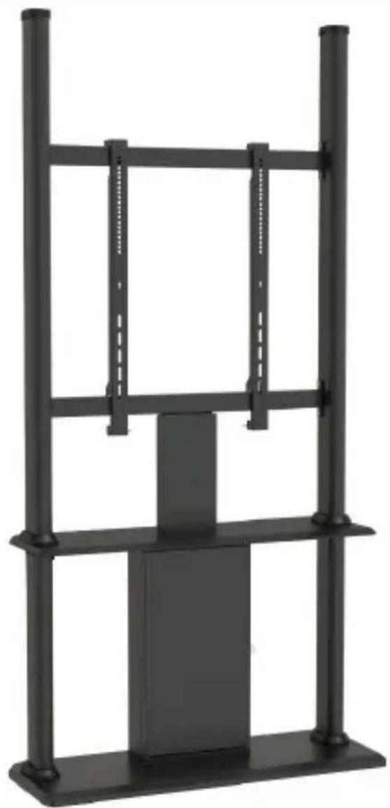
Digital Signage Display Kiosk | Portrait | Lockable
natural_image
Black metal shelving unit with vertical supports and a central rectangular block (no text or symbols visible)Actual product may vary from photos
User Manual
SKU#: DSIGNAGESTND
For the latest information and specifications visit
www.startech.com/DSIGNAGESTND
Use of Trademarks, Registered Trademarks, and other Protected Names and Symbols
This manual may make reference to trademarks, registered trademarks, and other protected names and/or symbols of third-party companies not related in any way to StarTech.com. Where they occur these references are for illustrative purposes only and do not represent an endorsement of a product or service by StarTech.com, or an endorsement of the product(s) to which this manual applies by the third-party company in question. Regardless of any direct acknowledgement elsewhere in the body of this document, StarTech.com hereby acknowledges that all trademarks, registered trademarks, service marks, and other protected names and/or symbols contained in this manual and related documents are the property of their respective holders.
To view manuals, videos, drivers, downloads, technical drawings, and more visit www.startech.com/support
Safety Statements
Safety Measures
• Cables (including power and charging cables) should be placed and routed to avoid creating electric, tripping or safety hazards.
Mesures de sécurité
• Make sure that you assemble this product according to the instructions.
- Do not exceed the weight capacity of this product. Overloading this product might result in injury or property damage. This product can support the following weight: 176 lb. (80 kg).
• This product is intended for indoor use only and should not be used outdoors.
• This enclosure is extremely heavy. Never attempt to move or lift this enclosure without assistance.
- Tipping hazard! This product is freestanding and inherently unstable especially when equipment is mounted. Therefore, it must be securely attached to the floor using the supplied or appropriate anchoring hardware.
- Keep liquid away from this enclosure.
- The floor anchoring hardware included with this product is designed for solid concrete floors. If you lack the necessary expertise to determine the suitability of the provided hardware for your floor, or how to safely anchor this product, contact a construction professional to anchor the stand or to provide specific instructions for your floor type.
Varningsmeddelanden
To view manuals, videos, drivers, downloads, technical drawings, and more visit www.startech.com/support
To view manuals, videos, drivers, downloads, technical drawings, and more visit www.startech.com/support
To view manuals, videos, drivers, downloads, technical drawings, and more visit www.startech.com/support
To view manuals, videos, drivers, downloads, technical drawings, and more visit www.startech.com/support
Safety Statements....2
Warning Statements....3
Product Diagram....9
Front View....9
Product Information 11
Package Contents 11
Technical Specifications....17
Requirements 17
Assembling the Display Kiosk....18
Attaching the Display Brackets (Flush) 34
Attaching the Display Brackets (Recessed)....35
Spacer Combinations ....38
Mounting the Display....39
Securing the Display Kiosk......43
Warranty Information......45
Limitation of Liability 45
To view manuals, videos, drivers, downloads, technical drawings, and more visit www.startech.com/support
Product Diagram
Front View

text_image
1 2 3 4 5 6 7 8 9 10To view manuals, videos, drivers, downloads, technical drawings, and more visit www.startech.com/support
| 1 | End Caps | 6 | Cable Bracket |
| 2 | Upper Column | 7 | Upper Base Board |
| 3 | Cross Bar | 8 | Lower Column |
| 4 | Display Bracket | 9 | Cabinet |
| 5 | Cable Ties | 10 | Lower Base Board |
Product Information
Package Contents
 Lower Base BoardQty: 1 Lower Base BoardQty: 1 | 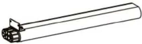 Lower ColumnsQty: 2 Lower ColumnsQty: 2 |
 Lower Column CapsQty: 4 Lower Column CapsQty: 4 |  CabinetQty: 1 CabinetQty: 1 |
To view manuals, videos, drivers, downloads, technical drawings, and more visit www.startech.com/support
 Upper Base BoardQty: 1 Upper Base BoardQty: 1 | 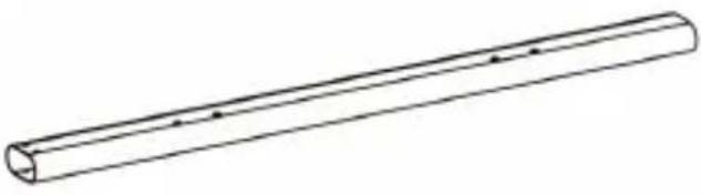 Upper Column LeftQty: 1 Upper Column LeftQty: 1 |
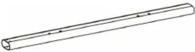 Upper Column RightQty: 1 Upper Column RightQty: 1 | 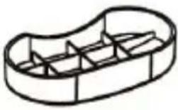 End CapsQty: 2 End CapsQty: 2 |
 Cross barsQty: 2 Cross barsQty: 2 | 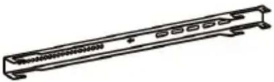 Display BracketsQty: 2 Display BracketsQty: 2 |
To view manuals, videos, drivers, downloads, technical drawings, and more visit www.startech.com/support

natural_image
Simple line drawing of a rectangular frame with mounting holes (no text or symbols)Cable Bracket Qty: 1

natural_image
Line drawing of a mechanical lever or handle (no text or symbols)Locking Brackets Qty: 2
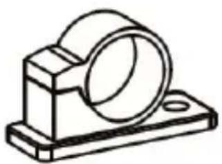
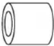
natural_image
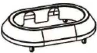
Technical line drawing of a mechanical bearing housing (no text or symbols)Cable Clips Qty: 2

Screw Caps Qty: 2
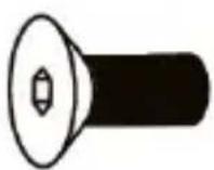
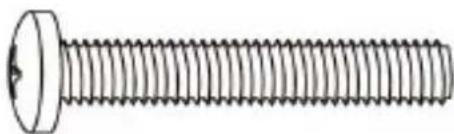
M10 x 25 mm Screws
Qty: 4

M6 x 12 mm Screws
Qty: 10
To view manuals, videos, drivers, downloads, technical drawings, and more visit www.startech.com/support
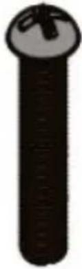
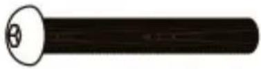 M8 x 60 mm ScrewsQty: 4 M8 x 60 mm ScrewsQty: 4 |  M8 NutsQty: 4 M8 NutsQty: 4 |
 M6 x 15 mm ScrewsQty: 8 M6 x 15 mm ScrewsQty: 8 |  M6 x 35 mm ScrewsQty: 2 M6 x 35 mm ScrewsQty: 2 |
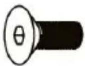
 M4 x 6 mm ScrewsQty: 2 M4 x 6 mm ScrewsQty: 2 | 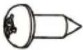 ScrewsQty: 2 ScrewsQty: 2 |
 M5 x 14 mm ScrewsQty: 4 M5 x 14 mm ScrewsQty: 4 |  M6 x 14 mm ScrewsQty: 4 M6 x 14 mm ScrewsQty: 4 |
To view manuals, videos, drivers, downloads, technical drawings, and more visit www.startech.com/support
 M6 x 30 mm ScrewsQty: 4 M6 x 30 mm ScrewsQty: 4 | 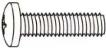 M8 x 30 mm ScrewsQty: 4 M8 x 30 mm ScrewsQty: 4 |
 M8 x 50 mm ScrewsQty: 4 M8 x 50 mm ScrewsQty: 4 |  Rectangular WashersQty: 4 Rectangular WashersQty: 4 |
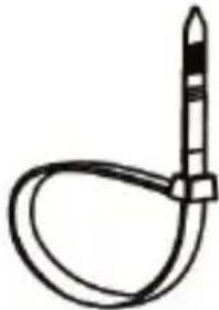 Cable TiesQty: 2 Cable TiesQty: 2 | 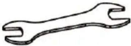 M6/M8 WrenchQty: 1 M6/M8 WrenchQty: 1 |
To view manuals, videos, drivers, downloads, technical drawings, and more visit www.startech.com/support
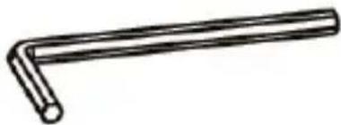 4 mm Hey KeyQty: 1 4 mm Hey KeyQty: 1 | 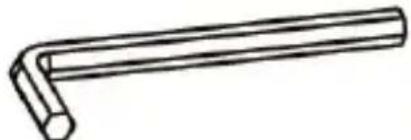 6 mm Hex HeyQty: 1 6 mm Hex HeyQty: 1 |
 5 mm Hey KeyQty: 1 5 mm Hey KeyQty: 1 |  Small Spacers'Qty: 8 Small Spacers'Qty: 8 |
 Large SpacersQty: 8 Large SpacersQty: 8 | 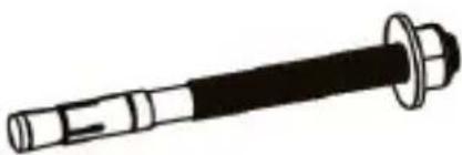 Floor AnchorQty: 1 Floor AnchorQty: 1 |
To view manuals, videos, drivers, downloads, technical drawings, and more visit www.startech.com/support
Technical Specifications
 Total Weight Total Weight | 80 kg (176 lb) |
 Screen Size Screen Size | 45" - 55" (1143 mm to 1397 mm) |
Requirements
• Phillips Head Screwdriver x 1
- A TV or Display compatible with VESA mounting holes patterns x 1
- Compatible VESA mounting hole patterns: 200x200, 200x300, 200x400, 300x200, 300x300, 400x200, 400x300, 400x400, 600x200, 600x300, 600x400
To view manuals, videos, drivers, downloads, technical drawings, and more visit www.startech.com/support
Assembling the Display Kiosk
-
Align the End Caps (x 2) with the Notches in the Lower Base Board.
-
Insert the End Caps into the Notches in the Lower Base Board.

natural_image
Technical line drawing of a rectangular electronic device with two circular ports and mounting holes (no text or symbols)Aligning the End Caps with the Lower Base Board
-
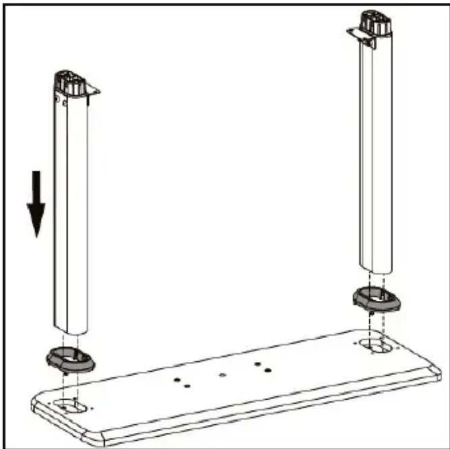
Align the bottom of the Lower Columns (x 2) with the End Caps. Make sure that the Bracket on the Lower Columns are at the top and facing inwards.
-
Insert the Lower Columns into the End Caps.
natural_image
Technical diagram showing two vertical cylindrical components mounted on a base plate with mounting holes, with an arrow indicating downward motion (no text or symbols present)Aligning the Lower Columns with the End Caps
-
Insert the M10 x 25 mm Screws (2 per column) through the Lower Base Board and End Caps and into the Lower Column.
-
Using the 6 mm Hex Key tighten the M10 x 25 mm Screws, being careful not to over-tighten.
To view manuals, videos, drivers, downloads, technical drawings, and more visit www.startech.com/support

natural_image
Technical diagram of a mechanical assembly with a central circular component and supporting legs, showing motion indicators (no text or symbols)Inserting the M10 x 25 mm Screws
-
Using the included Key, unlock the Cabinet Door.
-
Align the four interior Screw Hole inside the Cabinet with the four Screw Holes on the center of the Lower Base Board.
To view manuals, videos, drivers, downloads, technical drawings, and more visit www.startech.com/support

natural_image
Technical line drawing of a cabinet mounted on a base with two vertical posts, against a striped background (no text or symbols)Installing the Cabinet
-
Insert four M6 x12 mm Screws through the Screw Holes inside of the Cabinet and into the Screw Holes in the Lower Base Board.
-
Using the Phillips Head side of the 5 mm Hex Key, tighten the M6 x 12 mm Screws. Be careful not to over-tighten the M6 x 12 mm Screws.
To view manuals, videos, drivers, downloads, technical drawings, and more visit www.startech.com/support

natural_image
Technical diagram of a mechanical assembly with no visible text or symbolsInserting the M6 x 12 mm Screws
- Align the Column Holes on the Upper Base Board with the top of the Lower Columns
- Insert the top of the Lower Column into the Column Holes on the Upper Base Board. This should align the two center Screw Holes and the Cable Management Hole with the two Screw Holes and Cable Management Hole on the top of the Cabinet. Make sure that the two Screw Holes on the Upper Base Board align with the two Screw Holes on the Brackets on the Lower Columns.
To view manuals, videos, drivers, downloads, technical drawings, and more visit www.startech.com/support

natural_image
Technical line drawing of a mechanical enclosure with vertical supports and a top shelf, alongside a vertical barcode pattern (no text or symbols)Align the Upper Base Board with the Lower Columns
-
Insert two M6 x 12 mm Screws up through the Bracket on the Lower Column and into the Upper Base Board.
-
Using the Phillips Head side of the 5 mm Hex Key, tighten the M6 x 12 mm Screws. Be careful not to over-tighten the M6 x 12 mm Screws.
To view manuals, videos, drivers, downloads, technical drawings, and more visit www.startech.com/support

natural_image
Technical line drawing of a mechanical device with rotating base and circular motion path (no text or symbols)Tightening the M6 x 12 mm Screws
-
Repeat steps 11 - 12 to fasten the second Lower Column to the Upper Base Board.
-
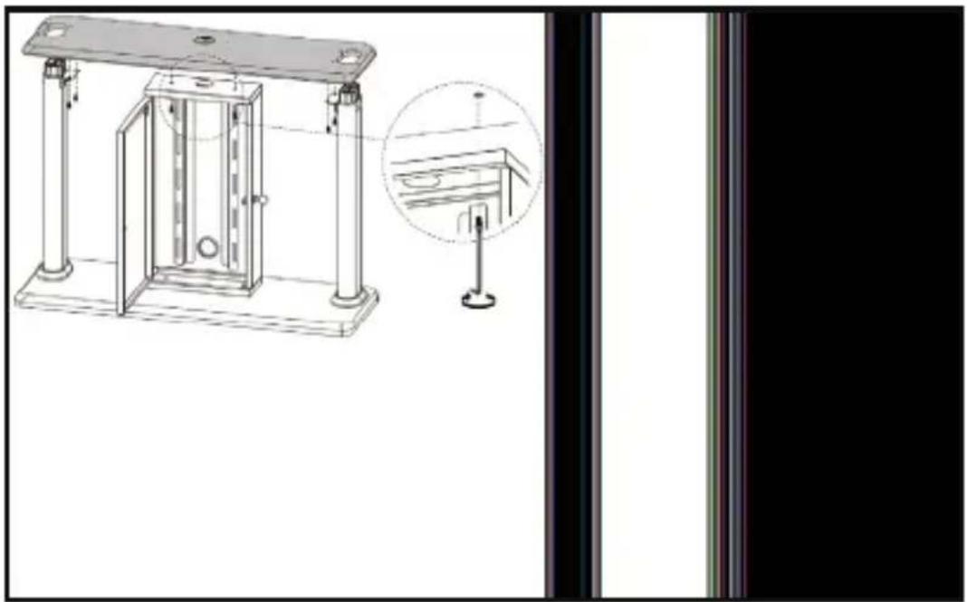
Insert two M6 x 12 mm Screws through the two Screw Holes on the inside of the Cabinet and up into the Upper Base Board.
To view manuals, videos, drivers, downloads, technical drawings, and more visit www.startech.com/support
natural_image
Technical line drawing of a mechanical device with mounting feet and a close-up inset showing internal components (no text or symbols)Installing the Upper Base Board
- Using the Phillips Head side of the 5 mm Hex Key, tighten the M6 x 12 mm Screws. Be careful not to over-tighten the M6 x 12 mm Screws.
- Align one of the Upper Columns with the top portion of the Lower Column that is protruding through the Upper Base Board.
Note: Make sure that the Screw Holes on the side of the Upper Column are facing inward.
To view manuals, videos, drivers, downloads, technical drawings, and more visit www.startech.com/support

natural_image
Technical diagram showing a vertical rod with downward arrow and a supporting frame (no text or symbols)Installing the Upper Column
- Align the Screw Holes (2 per side) on the lower portion of the Upper Column with the Screw Holes (2 per side) on the Lower Column that is protruding through the Upper Base Board.
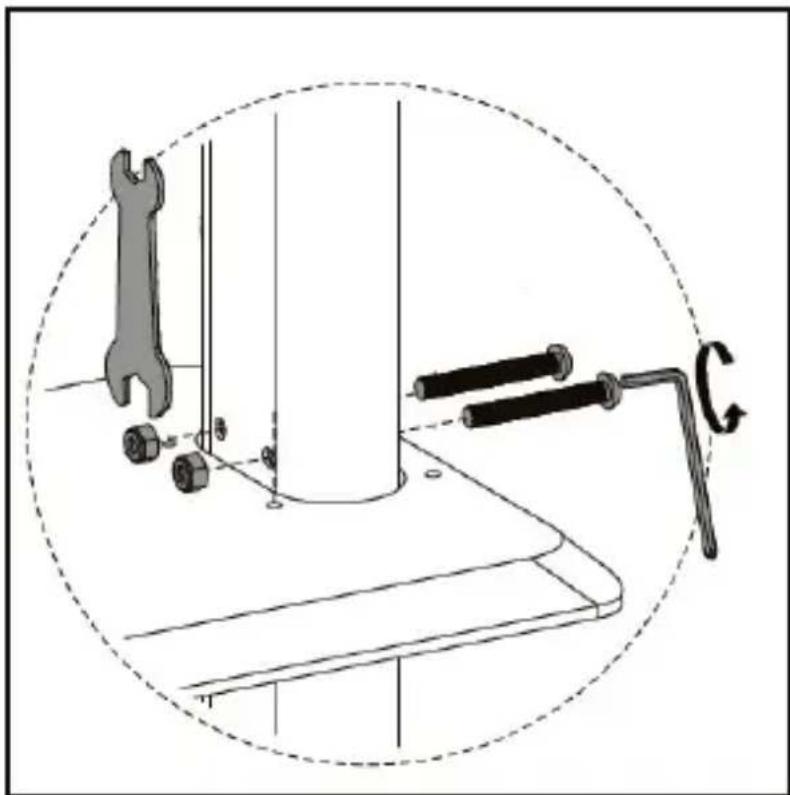
- Insert two M8 x 60 mm Screws through the Screw Holes on the Upper Column and the Screw Holes on the Lower Column and into the Nuts on the opposite side.
To view manuals, videos, drivers, downloads, technical drawings, and more visit www.startech.com/support
- Using the Wrench hold the Nut on the end of the M8 x 60 mm Screw, use the Hex side of the 5 mm Hex Key to tighten the M8 x 60 mm Screws.
natural_image
Technical diagram showing a wrench, screwdriver, and tool on a workbench with a dashed circular outline (no text or symbols)Attaching Upper Column
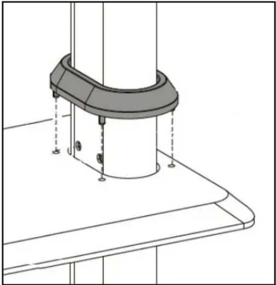
- Slide the Lower Column Cap over the top of the Upper Column and slide it down to the base (where the Upper Column is attached to the Lower Column). Snap the Lower Column Cap into the Holes (x 4) in the Upper Base Plate securing the Lower Column Cap in place.
To view manuals, videos, drivers, downloads, technical drawings, and more visit www.startech.com/support
natural_image
Technical line drawing of a mechanical assembly with a cylindrical component and mounting base (no text or symbols)Installing the Lower Column Cap
- Insert the End Cap on the top of the Upper Column.
To view manuals, videos, drivers, downloads, technical drawings, and more visit www.startech.com/support

natural_image
3D illustration of a vertical cylindrical object with a small circular top on top, no text or symbols presentInstalling End Cap
- Repeat steps 16 - 21 to install the second Upper Column.
- Align the Screw Holes on the Cross Bar Bracket with the interior Screw Holes on the Upper Columns.
Note: Make sure that the two Screw Holes in the center of the Cross Bar are facing towards the back of the Display Kiosk.
To view manuals, videos, drivers, downloads, technical drawings, and more visit www.startech.com/support

natural_image
Technical line drawing of a mechanical or electrical enclosure with vertical posts and a central horizontal bar (no text or symbols)Installing the Cross Bar
- Insert an M6 x 15 mm Screw (2 per bracket) through the Screw Holes on the Cross Bar Bracket and into the Upper Column.
- Using the 4 mm Hex Key tighten the M6 x 15 mm Screws. Be Careful not to over-tighten the M6 x 15 mm Screws.
To view manuals, videos, drivers, downloads, technical drawings, and more visit www.startech.com/support

natural_image
Technical diagram showing a mechanical assembly with two parts mounted on a vertical rod, enclosed in a dashed circular border (no text or symbols)Attaching the Cross Bar to the Upper Column
-
Repeat steps 23 - 25 to install the second Cross Bar.
-
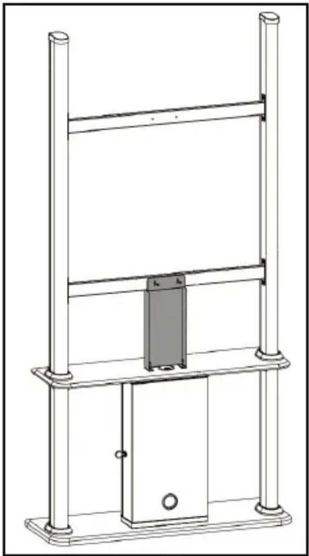
Align the Screw Holes on the top of the Cable Bracket (the top has a plate), with the Screw Holes on the center of the lower Cross Bar. Make sure that the Screw Holes on the bottom of the Cable Bracket are also aligned with the Screw Holes on the Upper Base Board, located on either sides of the Cable Management Hole.
To view manuals, videos, drivers, downloads, technical drawings, and more visit www.startech.com/support
natural_image
Technical line drawing of a mechanical lifting or mounting structure with vertical supports and a central rectangular component (no text or symbols)Installing the Cable Bracket
-
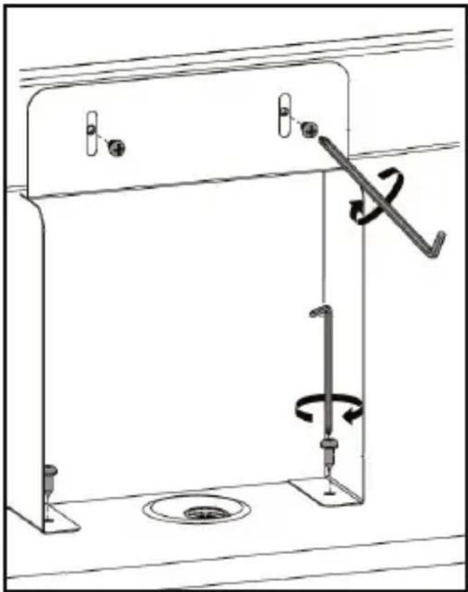
Insert two M4 x 6 mm Screws through the Screw Holes in the top plate on the Cable Bracket and into the center Screw Holes in the lower Cross Bar.
-
Using the Phillips Head tip on the 5 mm Hex Key tighten the M4 x 6 mm Screws. Be careful not to over-tighten the M4 x 6 mm Screws.
To view manuals, videos, drivers, downloads, technical drawings, and more visit www.startech.com/support
- Insert two Screws through the Screw Holes in the bottom of the Cable Bracket and into the Screw Holes in the Upper Base Board.
- Using the Phillips Head tip on the 5 mm Hex Key tighten the Screws. Be careful not to over-tighten the Screws.
natural_image
Technical line drawing of a mechanical assembly with rotating components and a spring mechanism (no text or symbols)Attaching the Cable Bracket
- Attach the two Cable Clips into the Holes in the center of the Cable Bracket. Make sure to attach the Cable Clips to the back of the Cable Bracket so that the cables are hidden when routing the cables.
To view manuals, videos, drivers, downloads, technical drawings, and more visit www.startech.com/support
Attaching the Display Brackets (Flush)
- Align the Screw Holes on the Display Brackets with the Screw Holes along the back of the Display. Make sure that the Display Brackets are aligned along the length of the Display, so that the Display can be mounted vertically.

natural_image
Technical line drawing of a mechanical assembly with two parallel plates and a central arrow indicating direction (no text or symbols)Aligning the Display Brackets
-
Select the appropriate Screws for mounting the Display Brackets (M5 x 14 mm, M6 x 14 mm, M6 x 30 mm, M8 x 30 mm, or M8 x 50 mm).
-
Align the appropriate Screw Hole on the Square Washer with the Screw Hole on the Display Bracket.
-
Insert the appropriate Screw through the Screw Hole in the Square Washer and Display Bracket and into the Screw Hole on the Display.
To view manuals, videos, drivers, downloads, technical drawings, and more visit www.startech.com/support
- Using a Phillips Head Screwdriver tighten the Screw. Be careful not to over-tighten.
Warning! Do not over-tighten the Screws. If you encounter resistance while you're tightening the Screws, stop tightening. Failure to do so could result in damage to the Display.

natural_image
Technical line drawing of a mechanical component with a central pin and mounting bracket, enclosed in a dashed circular boundary (no text or symbols)Attaching the Display Brackets
Attaching the Display Brackets (Recessed)
Note: Spacers can also be used for shortening the included Mounting Hardware.
- Select the appropriate Mounting Hardware for mounting the Display Brackets (M5 x 14 mm, M6 x 14 mm, M6 x 30 mm, M8 x 30 mm, or M8 x 50 mm and Spacers).
To view manuals, videos, drivers, downloads, technical drawings, and more visit www.startech.com/support
-
Align the Spacers with the Screw Holes along the back of the Display.
-
Align the Screw Holes on the Display Bracket with the Spacers.
-
Align the Square Washer with the Screw Holes on the Display Bracket.
-
Insert the appropriate Screw through the Screw Hole in the Square Washer, Display Bracket and Spacers and into the Screw Hole on the Display.

natural_image
Mechanical assembly diagram showing a clamping mechanism with no visible text or symbolsAligning the Spacers, Square Washer and Screw
- Using a Phillips Head Screwdriver tighten the Screw. Be careful not to over-tighten.
To view manuals, videos, drivers, downloads, technical drawings, and more visit www.startech.com/support
Warning! Do not over-tighten the Screws. If you encounter resistance while you're tightening the Screws, stop tightening. Failure to do so could result in damage to the Display.
Spacer Combinations
| Screw Type Spacer Combination | |||
 M6 x 30 mmorM8 x 30 mm M6 x 30 mmorM8 x 30 mm | 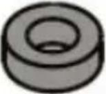 | 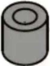 |   |
 M8 x 50 mm M8 x 50 mm |  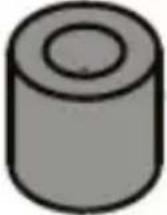 | 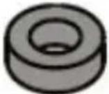 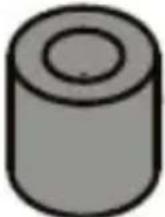  | 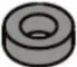   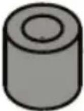 |
To view manuals, videos, drivers, downloads, technical drawings, and more visit www.startech.com/support
Mounting the Display
It is recommended that two people lift the Display onto the Display Kiosk.
Note: Use proper lifting techniques when lifting the Display.
- Lift the Display into position, aligning the Hooks on the Display Brackets with the Cross Bars.
- Attach the Hooks on the Display Brackets with the upper and lower Cross Bars.

natural_image
Technical line drawing of a mechanical testing apparatus with an inset close-up showing internal components (no text or symbols)
natural_image
Completely black image with no visible content or text.Attaching the Display to the Cross Bar
To view manuals, videos, drivers, downloads, technical drawings, and more visit www.startech.com/support
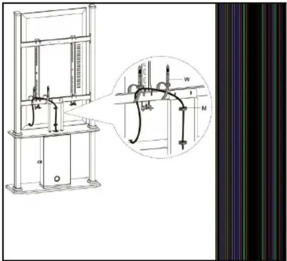
-
Insert a M6 x 35 mm Screw through the Screw Hole in the Display Bracket and into a Screw Cap.
-
Use the 5 mm Hex Key to tighten the M6 x 35 mm Screw. Be careful not to over-tighten.
-
(Optional) to deter the theft of the Display, slide the Locking Bracket through the two Notches (under the M6 x 35 mm Screw) on the Display Bracket. Insert a Lock (sold separately) through the hole at the end of the Locking Bracket.
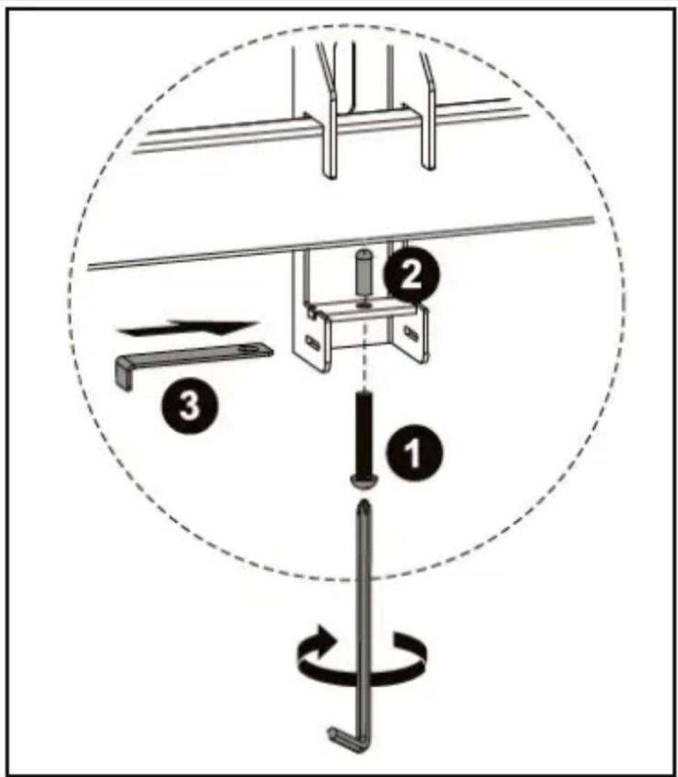
text_image
Diagram illustrating a mechanical assembly or tool path with numbered components and directional arrows, likely for assembly or maintenance.Securing the Display Bracket to the Cross Bars
-
Repeat steps 3 - 4 to secure the second Display Bracket to the Cross Bar.
-
Route the Display Cables along the Cross Bars and wrap a Cable Tie around a section of the Cross Bar where a Cable is running to secure it to the Cross Bar. Feed the tip of the Cable Tie through the fastener and pull the end securing the Cable to the Cross Bar.
To view manuals, videos, drivers, downloads, technical drawings, and more visit www.startech.com/support
-
Route the Display Cables down through the Cable Clips on the back of the Cable Bracket.
-
Finally route the Display Cables through the Cable Management Hole through the top of the Upper Base Board and connect them to the A/V Equipment or route them out the Cable Management Hole in the back of the Cabinet.
text_image
Technical diagram of a mechanical testing apparatus with labeled components and an inset close-up showing internal structure.Attaching the Cable Clips
To view manuals, videos, drivers, downloads, technical drawings, and more visit www.startech.com/support
Securing the Display Kiosk
The Display Kiosk must be secured to a level, flat surface by using the Floor Anchor, if suitable. The floor anchoring hardware included with this product is designed for solid concrete floors. If you lack the necessary expertise to determine the suitability of the provided hardware for your floor, or how to safely anchor this product, contact a construction professional to anchor the stand or to provide specific instructions for your floor type.
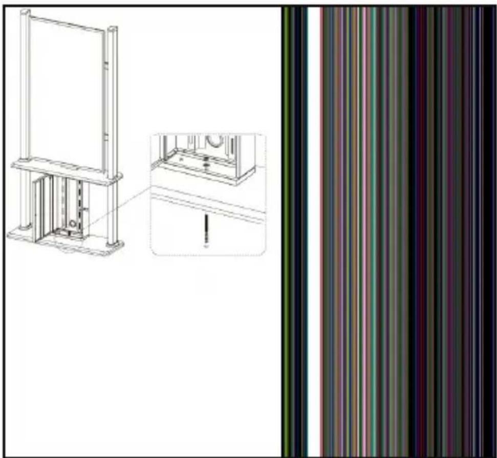
natural_image
Technical line drawing of a mechanical assembly with a vertical frame and side view, showing internal components and alignment (no text or symbols)Attaching the Floor Anchor
To view manuals, videos, drivers, downloads, technical drawings, and more visit www.startech.com/support
Note: Tipping Hazard! This product is freestanding and inherently unstable especially when equipment is mounted. Therefore, it must be securely attached to the floor using the supplied or appropriate anchoring hardware.
Warranty Information
This product is backed by a five-year warranty.
For further information on product warranty terms and conditions, please refer to www.startech.com/warranty.
Limitation of Liability
In no event shall the liability of StarTech.com Ltd. and StarTech.com USA LLP (or their officers, directors, employees or agents) for any damages (whether direct or indirect, special, punitive, incidental, consequential, or otherwise), loss of profits, loss of business, or any pecuniary loss, arising out of or related to the use of the product exceed the actual price paid for the product.
Some states do not allow the exclusion or limitation of incidental or consequential damages. If such laws apply, the limitations or exclusions contained in this statement may not apply to you.
Hard-to-find made easy. At StarTech.com, that isn't a slogan. It's a promise.
StarTech.com is your one-stop source for every connectivity part you need. From the latest technology to legacy products — and all the parts that bridge the old and new — we can help you find the parts that connect your solutions.
We make it easy to locate the parts, and we quickly deliver them wherever they need to go. Just talk to one of our tech advisors or visit our website. You'll be connected to the products you need in no time.
Visit www.startech.com for complete information on all StarTech.com products and to access exclusive resources and time-saving tools.
StarTech.com is an ISO 9001 registered manufacturer of connectivity and technology parts since 1985 with operations around the world.
Reviews
Share your experiences using StarTech.com products, including product applications and setup, what you love about the products, and areas for improvement.
StarTech.com Ltd.
45 Artisans
Crescent
London, Ontario
N5V 5E9
Canada
StarTech.com LLP
4490 South
Hamilton Road
Groveport, Ohio
43125
U.S.A.
StarTech.com Ltd.
Unit B, Pinnacle 15
Gowerton Road
Brackmills,
Northampton
NN4 7BW
United Kingdom
StarTech.com Ltd.
Siriusdreef 17-27
2132 WT
Hoofddorp
The Netherlands
FR: fr.startech.com
DE: de.startech.com
ES: es.startech.com
NL: nl.startech.com
IT: it.startech.com
JP: jp.startech.com