
STNDMTV70 - Wall mount StarTech.com - Free user manual and instructions
Find the device manual for free STNDMTV70 StarTech.com in PDF.


| Product Type | Wall Mount |
| Model | STNDMTV70 |
| Brand | StarTech.com |
| Maximum TV Size | 70 inches |
| Maximum Weight Capacity | 110 lbs (50 kg) |
| Compatible VESA Patterns | 200x200 to 600x400 mm |
| Mount Type | Fixed (low profile) |
| Material | Cold rolled steel |
| Color | Black |
| Dimensions (W x H x D) | 29.5 x 19.7 x 1.5 in (750 x 500 x 38 mm) |
| Product Weight | 8.8 lbs (4 kg) |
| Wall Plate Dimensions | 29.5 x 4.7 in (750 x 120 mm) |
| Distance from Wall | 1.5 in (38 mm) |
| Installation Tools Required | Stud finder, drill, level, socket wrench |
| Included Hardware | M4, M5, M6, M8 screws and spacers |
| Compatible Wall Types | Concrete, brick, wooden studs |
| Safety Certification | UL listed, TUV approved |
| Warranty | 5 years |
| Maintenance | Wipe with dry cloth; check screws periodically |
| Repairability | Replaceable hardware; no user-serviceable parts |
Frequently Asked Questions - STNDMTV70 StarTech.com
User questions about STNDMTV70 StarTech.com
0 question about this device. Answer the ones you know or ask your own.
Ask a new question about this device
Download the instructions for your Wall mount in PDF format for free! Find your manual STNDMTV70 - StarTech.com and take your electronic device back in hand. On this page are published all the documents necessary for the use of your device. STNDMTV70 by StarTech.com.
USER MANUAL STNDMTV70 StarTech.com
Mobile Media Center for Flat-Screen TV - One-Touch Height Adjustment
STNDMTV70
natural_image
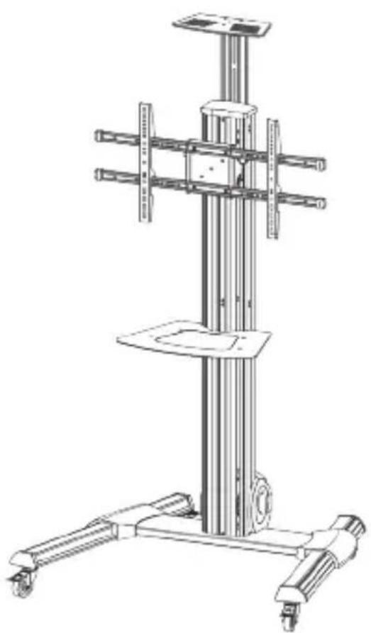
Technical line drawing of a vertical cylindrical device with multiple arms and wheels, no visible text or symbols*actual product may vary from photos
For the latest information, technical specifications, and support for this product, please visit www.StarTech.com/STNDMTV70.
Use of Trademarks, Registered Trademarks, and other Protected Names and Symbols
PHILLIPS ^® is a registered trademark of Phillips Screw Company in the United States or other countries.
This manual may make reference to trademarks, registered trademarks, and other protected names and/or symbols of third-party companies not related in any way to StarTech.com. Where they occur these references are for illustrative purposes only and do not represent an endorsement of a product or service by StarTech.com, or an endorsement of the product(s) to which this manual applies by the third-party company in question. Regardless of any direct acknowledgement elsewhere in the body of this document, StarTech.com hereby acknowledges that all trademarks, registered trademarks, service marks, and other protected names and/or symbols contained in this manual and related documents are the property of their respective holders.
Warning statements
Make sure that you assemble this product according to the instructions.
Read the entire manual and make sure that you understand the instructions before you start to assemble and use this product.
Do not exceed the weight capacity of this product. Overloading this product might result in injury or property damage.
Weight capacity of the multimedia shelf: 5 kg (11 lb.)
Weight capacity of the camera shelf: 5 kg (11 lb.)
Weight capacity of the TV mount: 40 kg (88 lb.)
Lift capacity of the TV mount: 8 to 25 kg (18 to 55 lb.)
Do not allow children to climb on this product, or use this product without proper supervision.
This product is intended for indoor use only and should not be used outdoors.
When you assemble this product, do not over-tighten the screws. If you encounter resistance when you are tightening the screws, stop tightening.
Assembling this product is a two-person task. Do not attempt to assemble this product and install equipment without assistance.
Before you add equipment to this product, make sure that you have properly assembled and installed it, and that the product can support the weight of the equipment that you are adding to it.
Make sure that you properly install all of your equipment before you start to adjust this product.
For safety reasons, when you add or remove equipment and change the weight of the mounted load, you need to follow the steps in the manual to readjust this product.
Stored energy hazard! The column in this product contains a lift mechanism that could move up quickly when you remove the loaded equipment. Before you remove equipment or make adjustments to the lift tension, move the display to the highest position on the column. Failure to do so could result in injury or property damage.
Tipping hazard! Do not move the cart while the display is in the highest position. Also, do not move the cart by pushing on the display.
Do not move the cart over cords, cables, or uneven surfaces.
Before you start to move the cart, make sure that you unlock the casters.
Varningsmeddelanden
Product diagram....2
Technical specifications .... 3
Package contents....4
Requirements 10
Assembly....11
Assemble the base....11
Adjust the height of the casters....12
Attach the column to the base....13
Assemble the TV mount 16
Attach the support plate to the column....17
Move the support plate to the lowest position 19
Attach the adapter brackets to a flush mounting surface 21
Attach the adapter brackets to a recessed mounting surface....23
Attach the TV to the column....26
Counterbalance the weight of the TV....29
Attach the plastic cover 30
Attach the cable clips 32
Install the multimedia shelf....33
Attach the camera shelf....36
Attach the wrench 38
Adjusting the STNDMTV70....39
Change the orientation of the TV....39
Adjust the angle of the TV 40
Adjust the height of the multimedia shelf....41
Adjust the height of the camera shelf 42
Lock the vertical position of the TV 43
Technical support....44
Warranty information....44
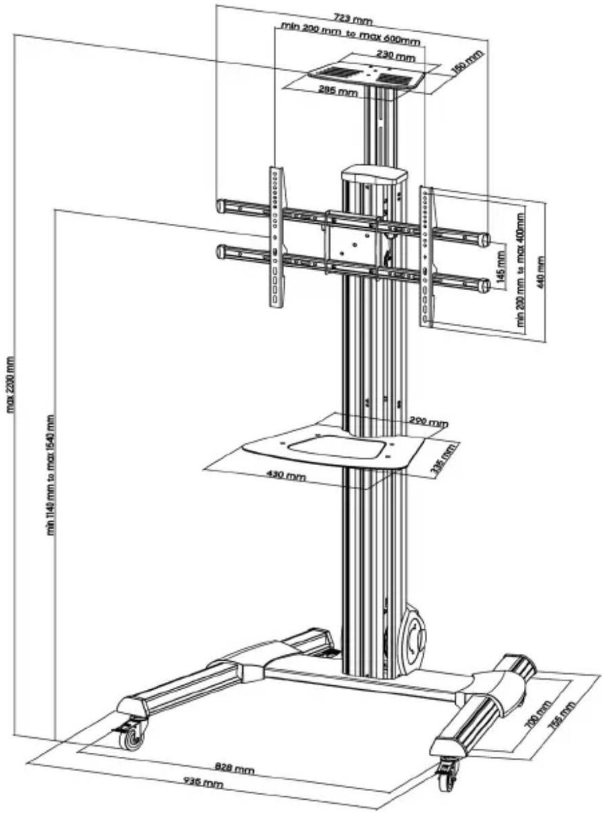
Introduction Product dimensions
Support plate rotation: 0^ to +90^
TV tilt: +5° to -12°
Product diagram
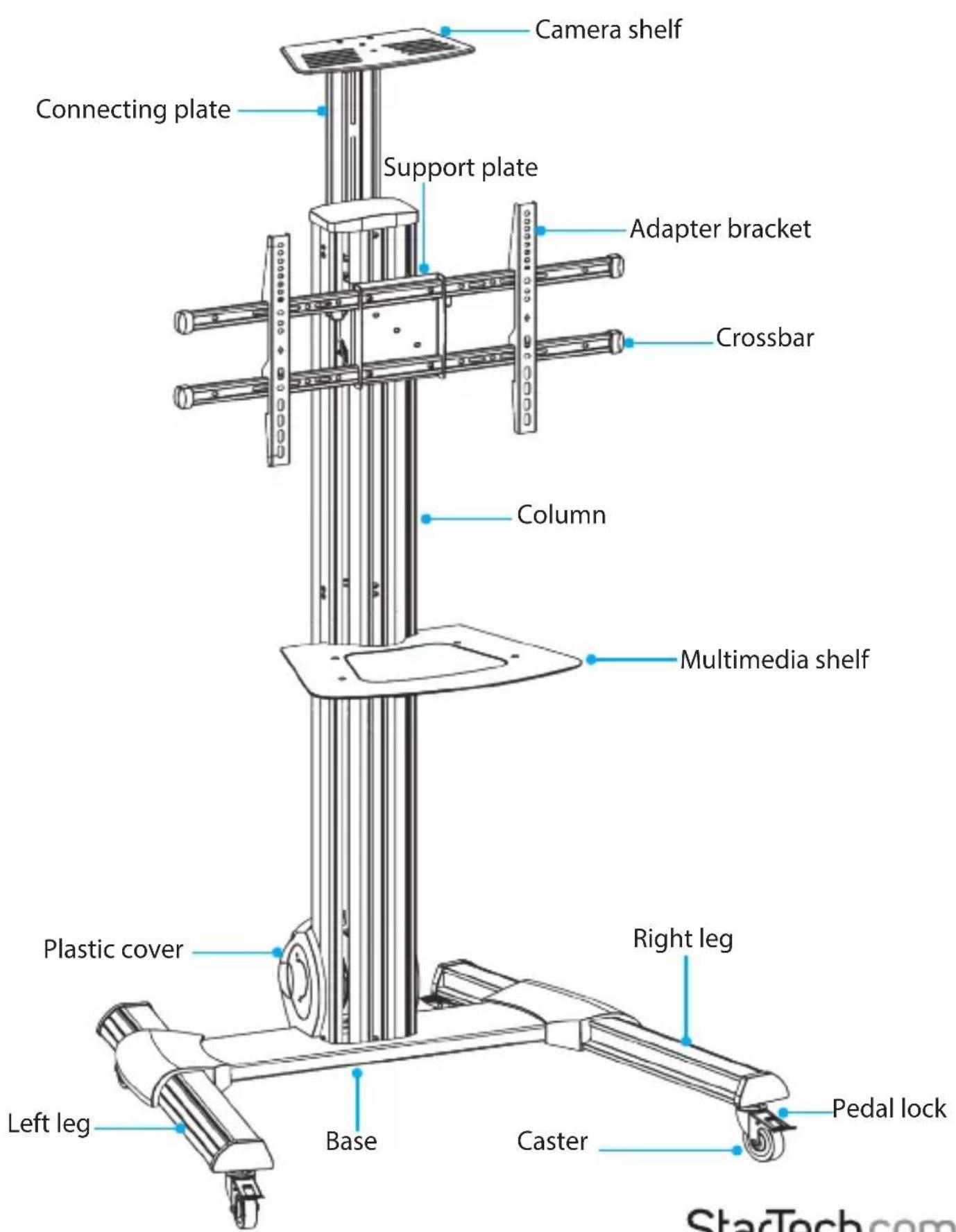
Instruction manual
Technical specifications
Unless otherwise indicated, the technical specifications in the table below apply to the TV.
Type of measurement Measurement
| VESA mounting hole pattern on the TV mount | 200x200 400x300 |
| 200x300 400x400 | |
| 200x400 600x200 | |
| 300x200 600x300 | |
| 300x300 600x400 | |
| 400x200 | |
| Weight capacity of TV mount | 40 kg(88 lb.) |
| Lift capacity of TV mount | 8 to 25 kg (18 to 55 lb.)Note: If you exceed the lift capacity, you will require additional manual force to raise the TV. |
| Weight capacity of multimedia shelf | 5 kg (11 lb.) |
| Weight capacity of camera shelf | 5 kg (11 lb.) |
| Screen size | 32" to 75" |
Package contents
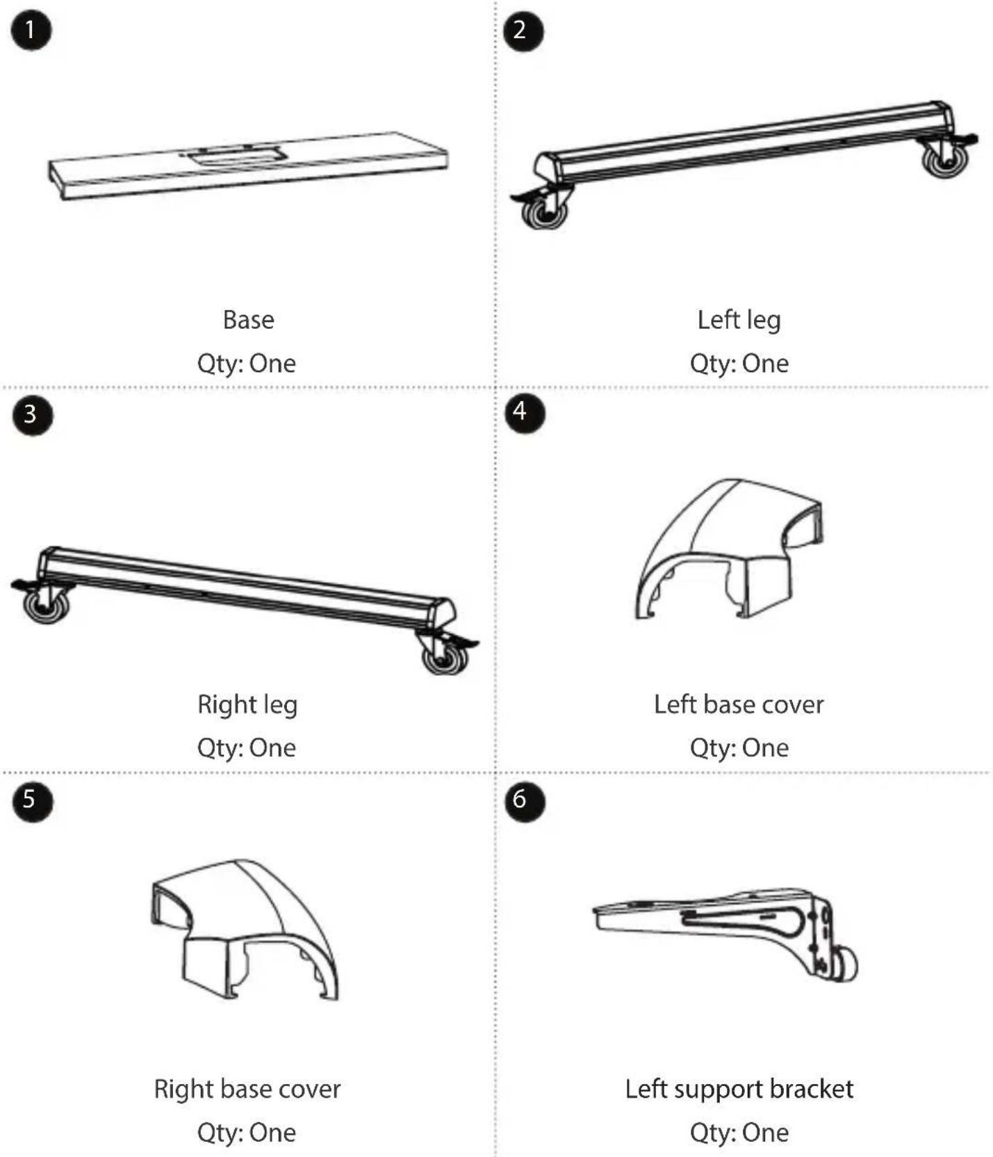
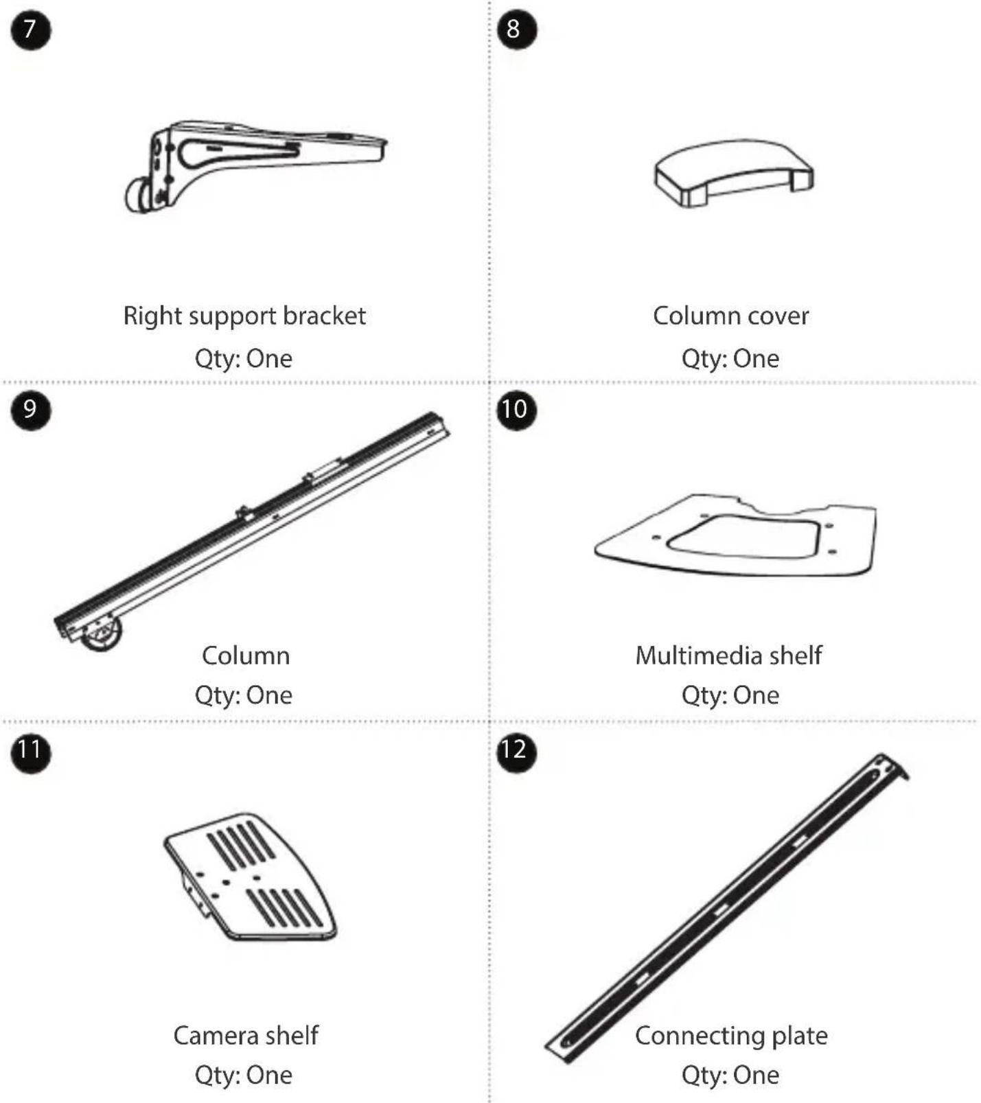
Right support bracket
Qty: One
Column cover
Qty: One
Column
Qty: One
Multimedia shelf
Qty: One
Camera shelf
Qty: One
Connecting plate
Qty: One
13
natural_image
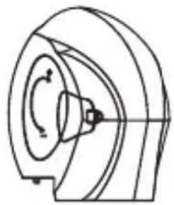
Technical line drawing of a mechanical component with no visible text or symbolsPlastic cover Qty: One
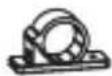
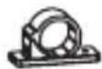
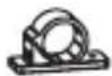
Cable clips Qty: Three
15

natural_image
Pure diagram of a mechanical or electronic component with no text, numbers, or symbols
natural_image
Pure electrical circuit lines without any symbolsAdapter brackets Qty: Two
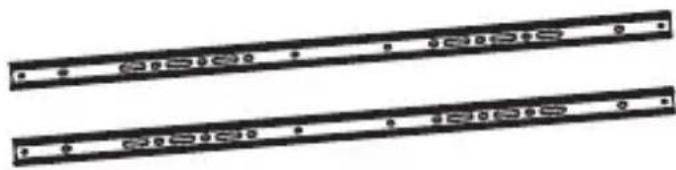
natural_image
Two parallel black rectangular electronic components with mounting holes, no visible text or symbolsCrossbars Qty: Two
17


End caps Qty: Four
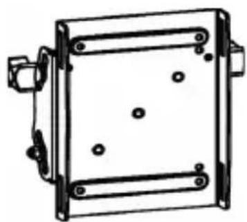
natural_image
Technical line drawing of a square mechanical housing or enclosure with mounting brackets and internal components (no text or symbols)Support plate Qty: One
| 19 | 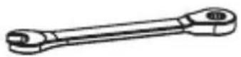 | 20 | 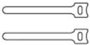 |
| Wrench Qty: One | Hook-and-loop ties Qty: Two | ||
| 21 | 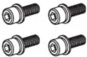 | 22 | 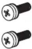 |
| M6x16 mm screws Qty: Four | M6x25 mm screws Qty: Two | ||
| 23 | 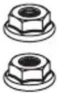 | 24 | 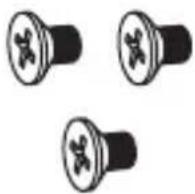 |
| Support plate nuts Qty: Two | Countersunk screws Qty: Three |
25
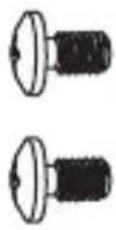
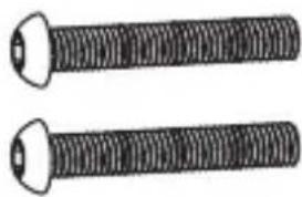
M4x6 mm screws
Qty: Two
27
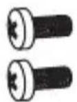
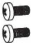
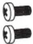
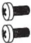
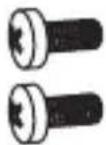
M6x14 mm screws
Qty: Ten
29
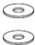
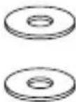
Washers
Qty: Four
26
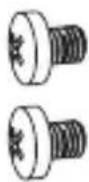
M6x8 mm screws
Qty: Six
28
natural_image
Two identical threaded metal rods with flanged ends (no text or symbols visible)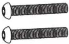
natural_image
Two identical threaded metal rods with flanged ends (no text or symbols visible)M8x25 mm screws
Qty: Four
30
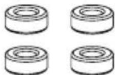
Shelf spacers
Qty: Four
31
natural_image
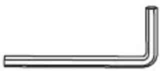
Simple L-shaped metal pipe or angle bracket diagram (no text or symbols)Hex key
Qty: One
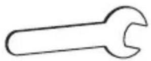
Caster wrench
Qty: One
33
natural_image
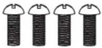
Four identical screwdrivers with dome caps, shown in a row (no text or symbols)M5x14 mm screws
Qty: Four
natural_image
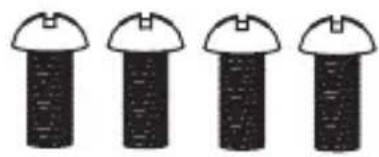
Four identical black-and-white diagrams of a screw with a dome-shaped head, arranged horizontally (no text or symbols)M6x14 mm screws
Qty: Four
35
natural_image
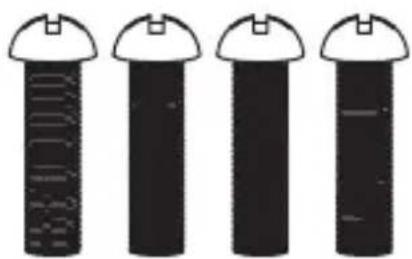
Four identical black cylindrical objects with white caps, each containing a vertical scale or measurement markings (no text or symbols visible)M6x30 mm screws
Qty: Four
36
natural_image
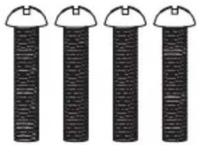
Four identical black-and-white cylindrical objects with circular tops, arranged horizontally (no text or symbols visible)M8x30 mm screws
Qty: Four
37
natural_image
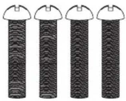
Four identical cylindrical objects with wavy patterns and circular bases, each topped with a small triangular cap (no text or symbols visible)M8x50 mm screws
Qty: Four
natural_image
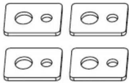
Four identical 3D rectangular blocks with two circular holes, arranged in a 2x2 grid (no text or symbols)TV washers
Qty: Four
39
natural_image
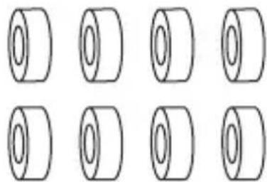
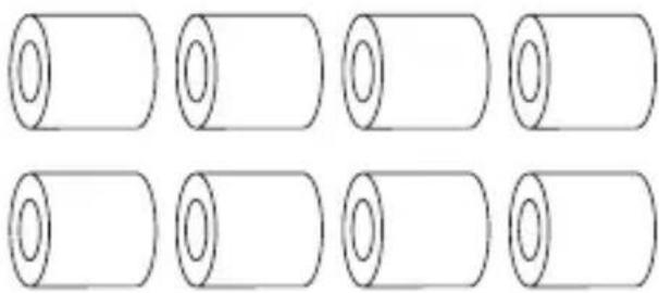
Eight identical cylindrical objects arranged in two rows (no text or symbols)Small spacers
Qty: Eight
40
natural_image
Six identical cylindrical shapes arranged in two rows, each with a separate inner circle (no text or symbols)Large spacers
Qty: Eight
41
Requirements
- A TV compatible with the following VESA mounting holes patterns: 200x200, 200x300, 200x400, 300x200, 300x300, 400x200, 400x300, 400x400, 600x200, 600x300, 600x400
- A Phillips™ type screwdriver Requirements are subject to change. For the latest requirements, please visit www.StarTech.com/STNDMTV70.
Assembly
Warning! Assembling this product requires multiple people. DO NOT attempt to assemble this product and install equipment without assistance.
Assemble the base
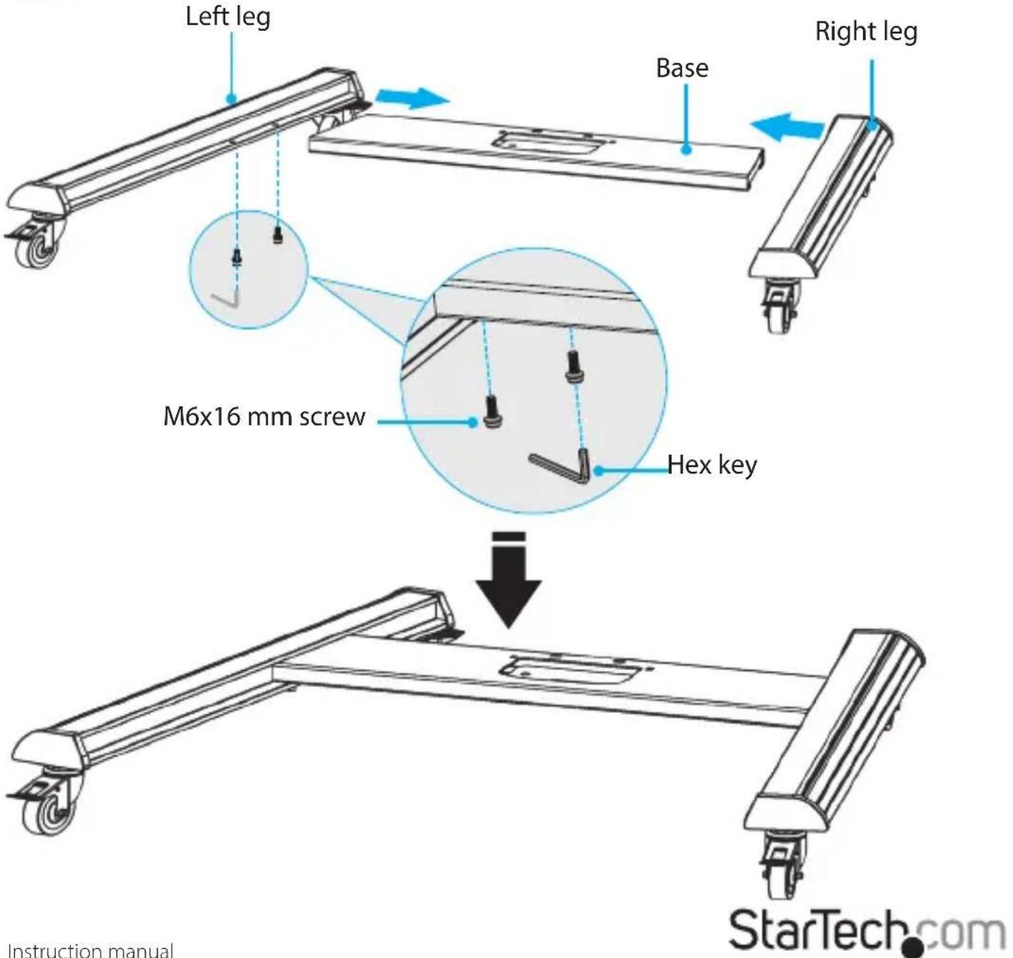
- Insert the base into the left leg, aligning the holes in the base with the holes in the left leg.
- Insert two M6x16 mm screws through the left leg and into the base.
- Use the hex key to tighten the M6x16 mm screws.
- Repeat steps 1 to 3 to attach the right leg. (figure 1)
figure 1
Adjust the height of the casters
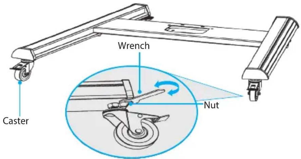
You can adjust the height of each of the four casters so that the casters are balanced and the assembly doesn't rock.
- Use the caster wrench to loosen the nuts above the casters.
- Rotate the casters counterclockwise or clockwise to raise or lower the casters to the desired height.
- Use the caster wrench to tighten the nuts. (figure 2)
figure 2
Attach the column to the base
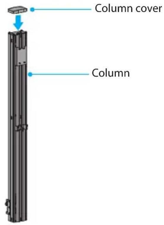
- Snap the column cover onto the top of the column. (figure 3)
figure 3
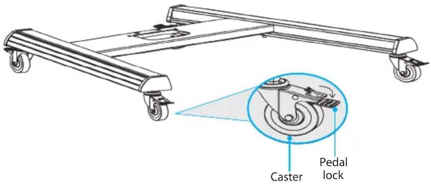
- Press the pedal locks down on each of the casters to lock them in place and prevent the legs from moving as you attach the column. (figure 4)
figure 4
-
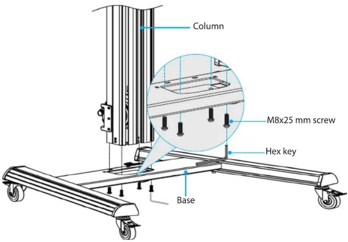
Line up the holes in the bottom of the column with the holes in the base.
-
While another person holds the column upright, insert the four M8x25 mm screws through the base and into the column.
-
Use the hex key to tighten the M8x25 mm screws. (figure 5)
figure 5
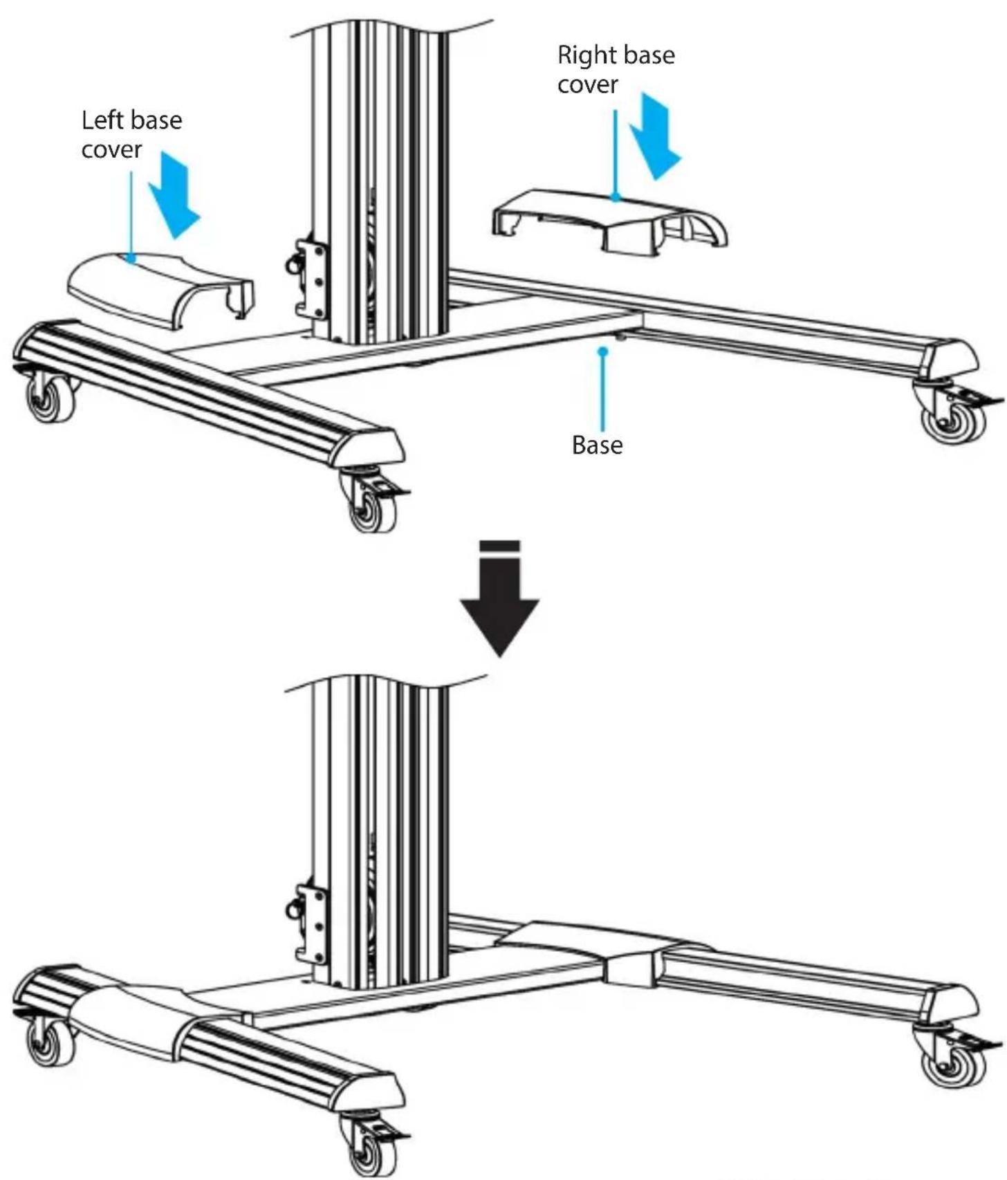
- Snap the left base cover and the right base cover onto the base and legs. (figure 6)
figure 6
Assemble the TV mount
- Slide the crossbars through the top and bottom openings in the support plate. (figure 7)
figure 7
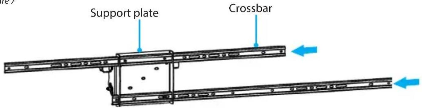
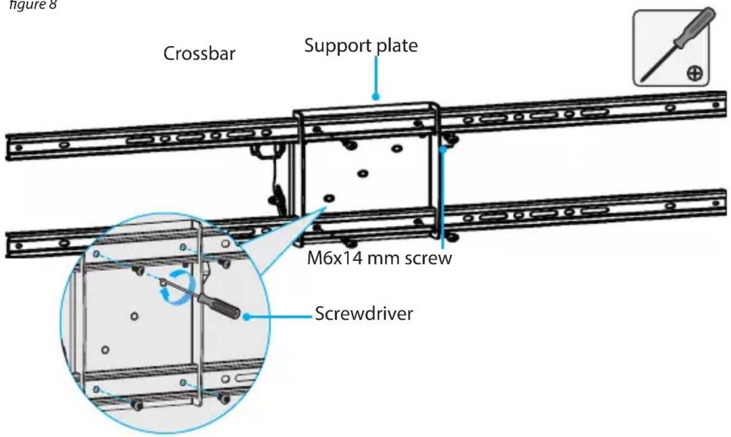
- Position the crossbars so that they are centered on the support plate and the holes on the crossbars are aligned with the holes in the support plate.
- Insert four of the M6x14 mm screws through the crossbars and into the support plate. (figure 8)
- Use a Phillips type screwdriver to tighten the M6x14 mm screws.
figure 8
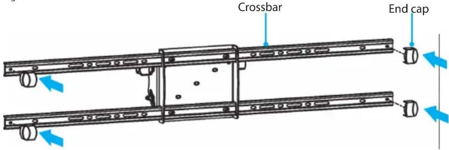
- Snap an end cap onto each of the four ends of the crossbars. (figure 9)
figure 9
Attach the support plate to the column
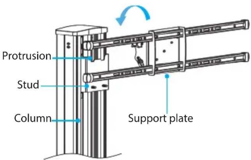
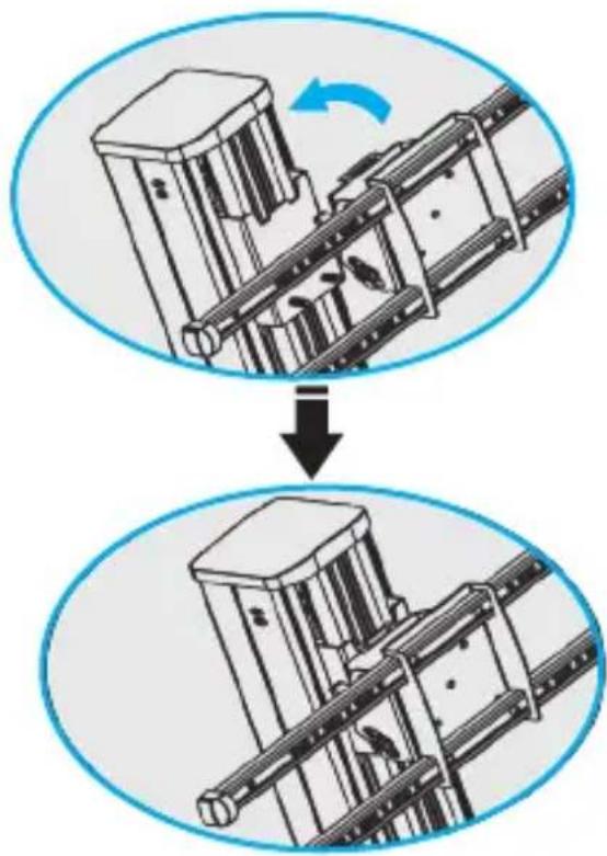
- Lift up the support plate and hook the top of the support plate onto the protrusion and the studs on the column. (figure 10)
figure 10
flowchart
graph TD
    A["Initial Component"] --> B["Assembly Step"]
    B --> C["Final Assembly Unit"]
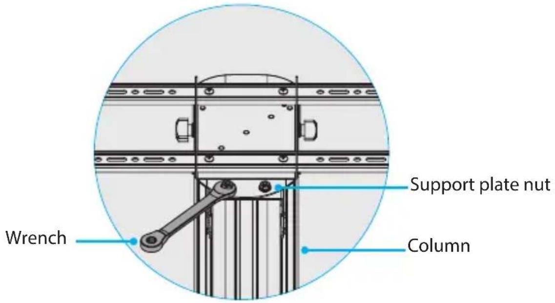
- Place the support plate nuts over the studs on the column and use your fingers to tighten the support plate nuts.
- Use the wrench to finish tightening the support plate nuts. (figure 11)
figure 11
Move the support plate to the lowest position
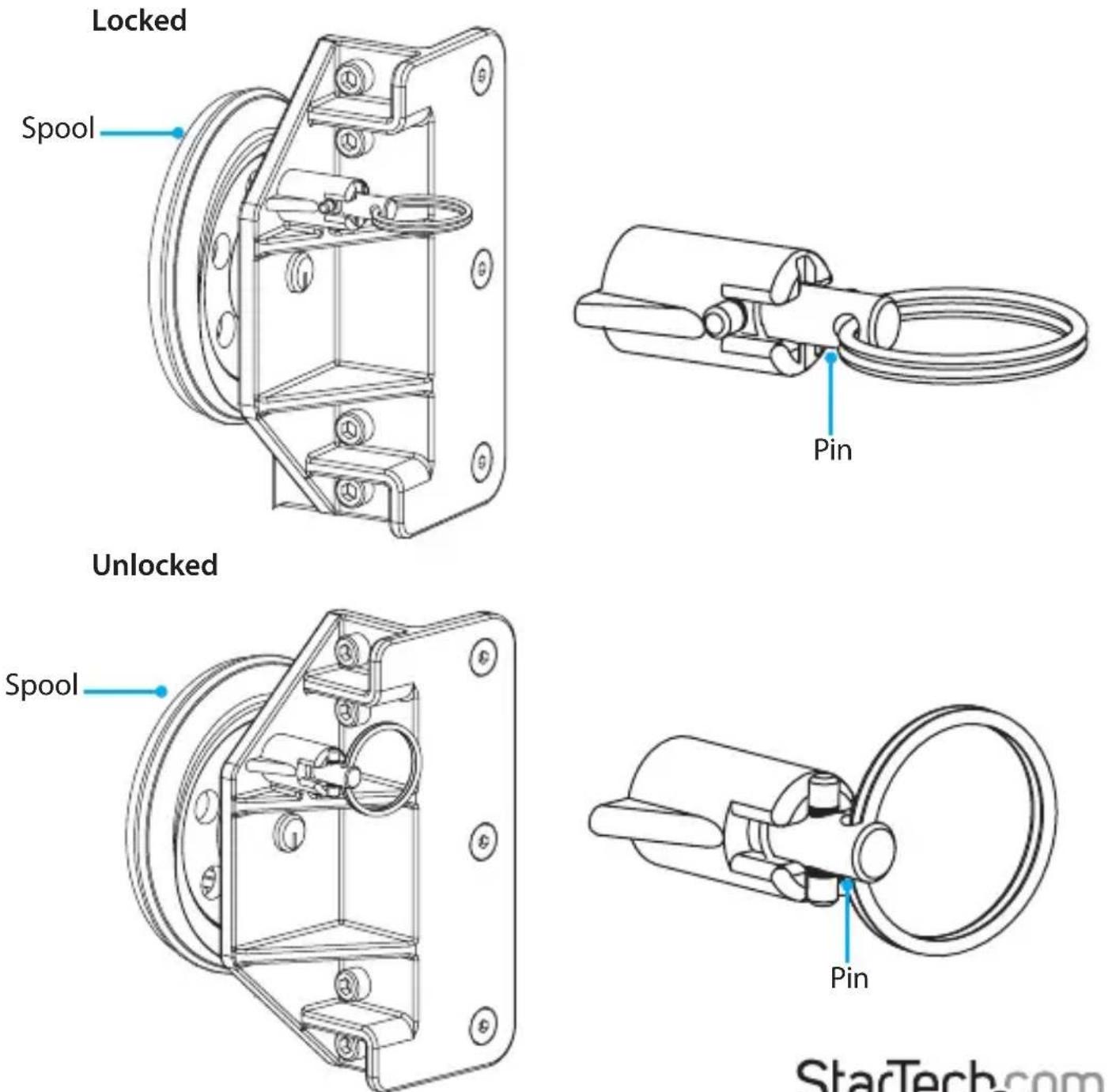
When the spring-loaded pin is positioned in one of the holes in the side of the spool at the bottom of the column, the vertical position of the TV is locked and you can't move the TV up or down the column. (figure 12)
If you pull the pin out of the spool and turn it to the unlocked position (figure 12), the TV is no longer locked in place and can be moved up or down the column.
Caution! You should avoid leaving the pin in the unlocked position.
Warning! Exercise caution when you pull the pin out of the spool and turn it to the unlocked position. The weight of the TV or support plate may not be counterbalanced and could free fall down the column or spring upwards, resulting in damage to the TV or support plate, or personal injury.
figure 12
Instruction manual
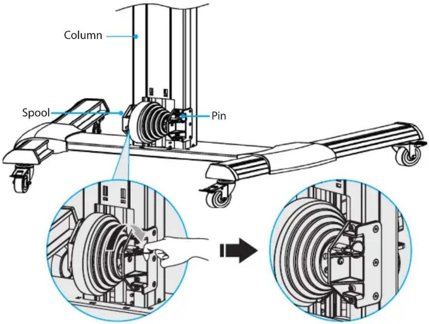
- To unlock the vertical position of the support plate, at the bottom of the column, next to the spool, pull the pin out and turn it to the unlocked position. (figure 13)
figure 13
- Pull the support plate and adapter brackets down until they are at the bottom of the column.
- Pull the pin and turn it to the locked position.
- To make sure that the pin is properly aligned in one of the holes, pull up or push down on the support plate. You may hear a clicking sound as the spring-loaded pin goes into the hole and prevents the spool from rotating.
Caution! If the pin is misaligned and isn't fully inserted into one of the holes on the spool, the vertical position isn't locked and the TV could free fall down the column or spring upwards, resulting in damage to the TV or personal injury.
When the pin is aligned in one of the holes and the support plate is locked in place, it shouldn't move if you pull up or push down on it.
Attach the adapter brackets to a flush mounting surface
To accommodate different TV designs, the STNDMTV70 comes with five sets of screws of different lengths and diameters, TV washers with two hole sizes, and two sizes of spacers.
Warning! Make sure that the weight of the TV doesn't exceed the weight capacity of this product. If you exceed the weight capacity, you might experience personal injury or damage to the product. This product can support the following weight: 40 kg (88 lb.) when the lift mechanism is locked or 8 to 25 kg (18 to 55 lb.) when the lift mechanism is in use.
-
To select the combination of mounting hardware that you need to use to attach the adapter brackets to the TV, complete the following:
-
Determine the depth of the mounting holes on the TV.
- Determine the diameter of the mounting holes on the TV.
Note: If you're using a TV with a flush mounting surface, you don't need to use any of the provided spacers.
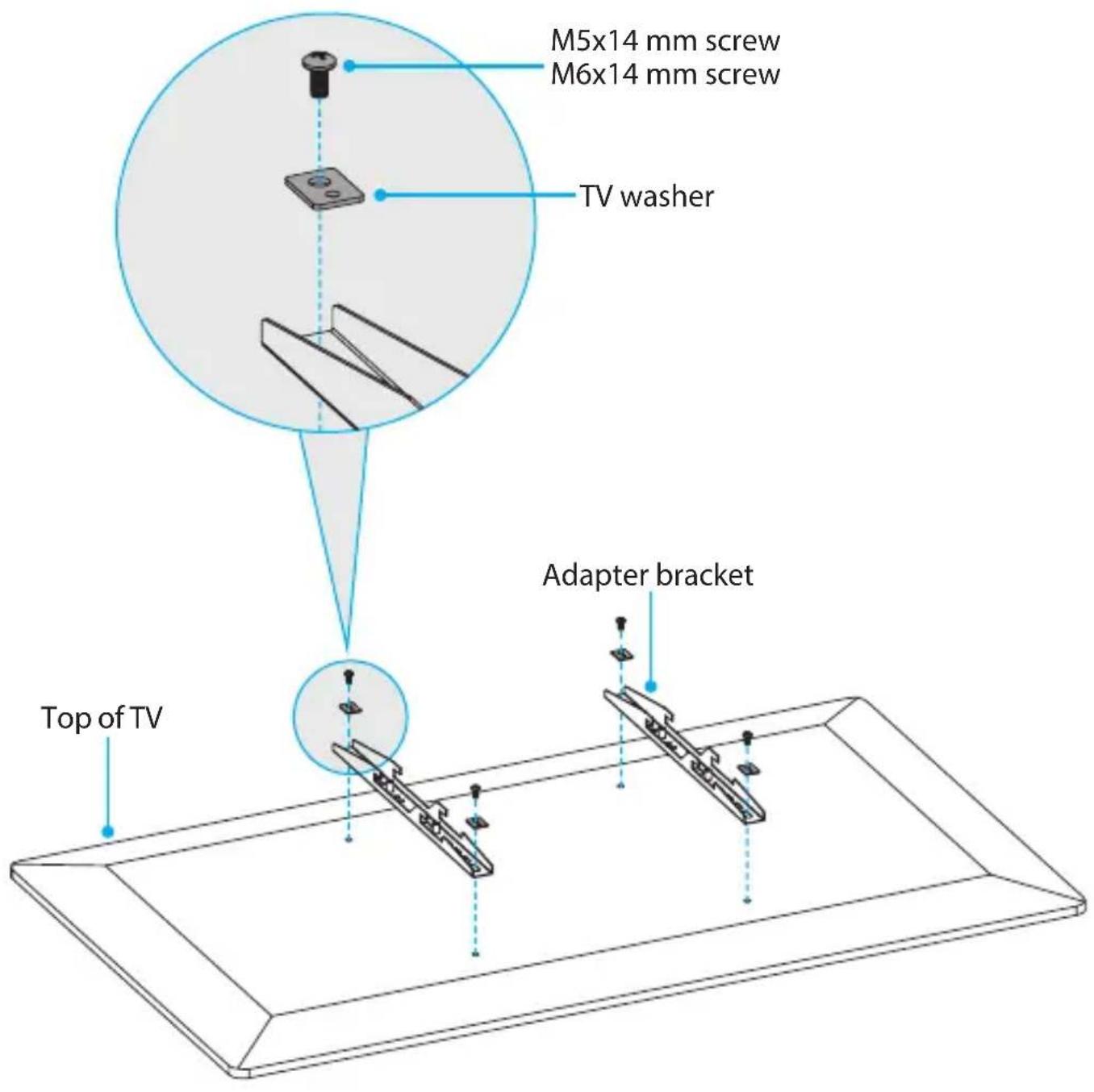
- Position the adapter brackets so that the hooks on the adapter brackets are pointed towards the bottom of the TV and are aligned with the mounting holes on the back of the TV.
- Depending on the screw size that you're using, place the TV washers so that either the small or large holes are positioned over the adapter brackets.
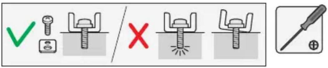
- Insert the M5x14 mm screws or the M6x14 mm screws through the TV washers, adapter brackets, and into the back of the TV.
- Use a Phillips type screwdriver to tighten the screws. (figure 14)
Warning! Do not over-tighten the screws. If you encounter resistance while you're tightening the screws, stop tightening. Failure to do so could result in damage to the TV.
figure 14
Attach the adapter brackets to a recessed mounting surface
To accommodate different TV designs, the STNDMTV70 comes with five sets of screws of different lengths and diameters, TV washers with two hole sizes, and two sizes of spacers.
Warning! Make sure that the weight of the TV doesn't exceed the weight capacity of this product. If you exceed the weight capacity, you might experience personal injury or damage to the product. This product can support the following weight: 40 kg (88 lb.) when the lift mechanism is locked or 8 to 25 kg (18 to 55 lb.) when the lift mechanism is in use.
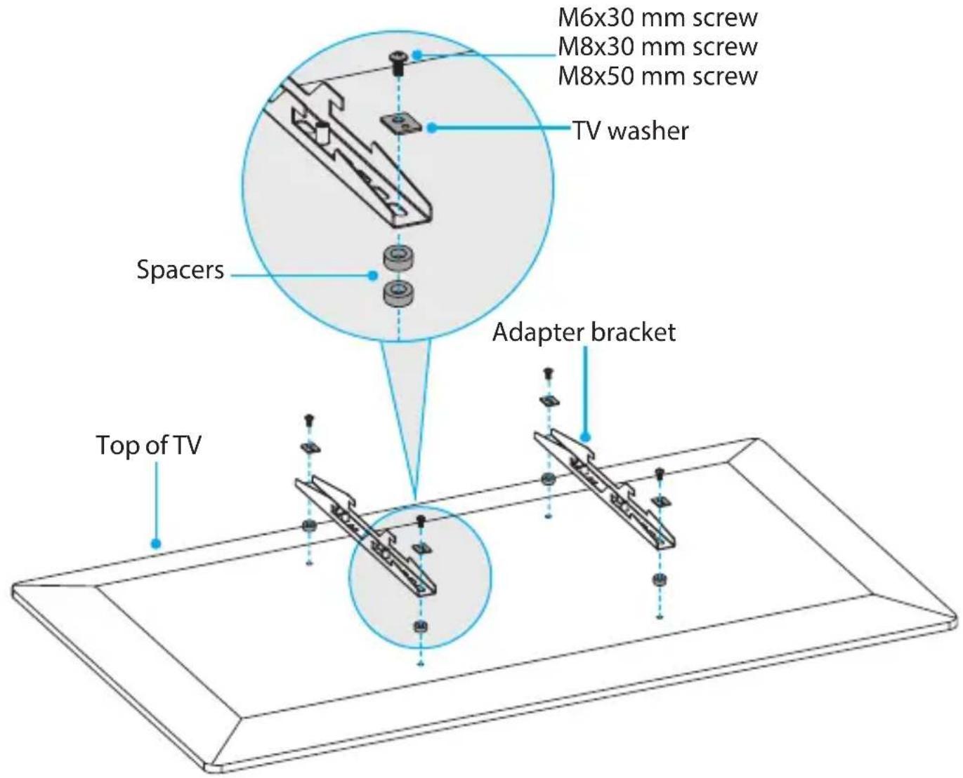
- To select the combination of mounting hardware that you need to use to attach the adapter brackets to the TV, complete the following:
• Determine the depth of the mounting holes on the TV.
• Determine the diameter of the mounting holes on the TV.
- Consult the images below and on the next page to see the different hardware combinations available, and select the one that works best with the TV.
M6x30 mm screw
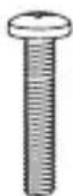
or
M8x30 mm screw
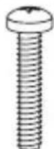
combined with
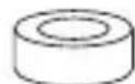
or
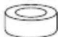
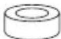
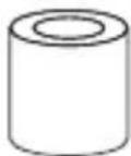
or
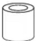
2 small spacers
1 small spacer
1 large spacer
1 large spacer
M8x50 mm hardware combinations are illustrated on the next page
M8x50 mm
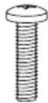
combined with
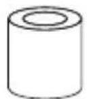
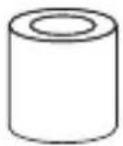
or
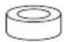
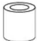
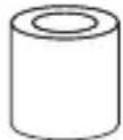
or
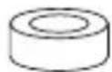
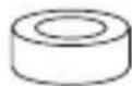
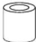
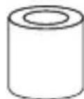
2 large spacers
1 small spacer
2 large spacers
2 small spacers
2 large spacers
- Position the adapter brackets so that the hooks on the adapter brackets are pointed towards the bottom of the TV and are aligned with the mounting holes on the back of the TV.
- Depending on the screw size that you're using, place the TV washers so that either the small or large holes are positioned over the adapter brackets.
- Insert the M6x30 mm screws, M8x30 mm screws, or the M8x50 mm screws through the TV washers, adapter brackets, spacers, and into the back of the TV.
- Use a Phillips type screwdriver to tighten the screws. (figure 15)
Warning! Do not over-tighten the screws. If you encounter resistance while you're tightening the screws, stop tightening. Failure to do so could result in damage to the TV.
figure 15

Attach the TV to the column
Warning! Attaching the TV requires multiple people. Do not attempt to complete this task by yourself.
Warning! Make sure that you move the support plate to the lowest position on the column before you attach the TV. For more information, see the "Move the support plate to the lowest position" section.
- If you haven't done so already, press the pedal locks down on each of the casters to prevent the legs from moving as you attach the TV to the column.
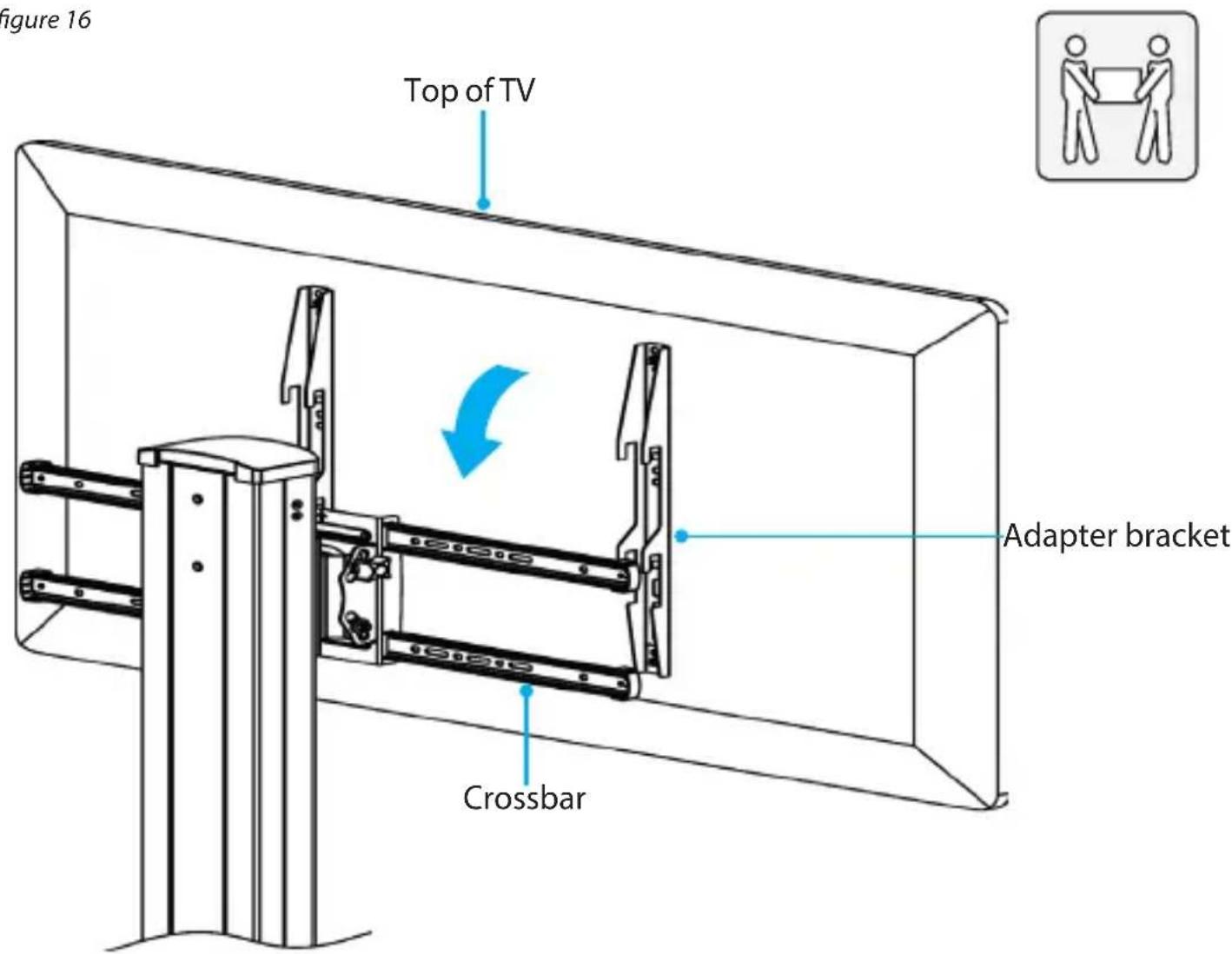
- With a person holding each side of the TV, carefully lift up the TV and hook the adapter brackets over the crossbars. (figure 16)
- Center the TV on the crossbars, and insert four M6x14 mm screws through the crossbars and into the adapter brackets. (figure 17)
- Use a Phillips type screwdriver to tighten the M6x14 mm screws.
figure 17
natural_image
Two technical icons: one showing two figures exchanging a document, the other showing a screwdriver with a plus symbol (no text or labels)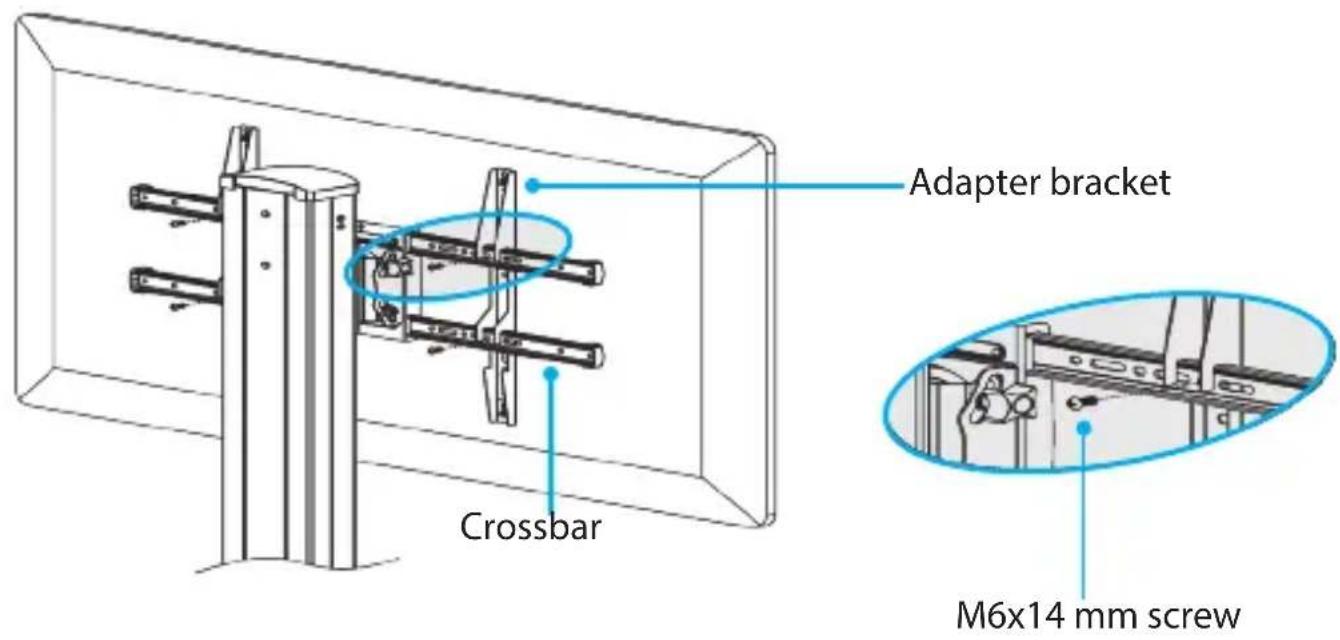
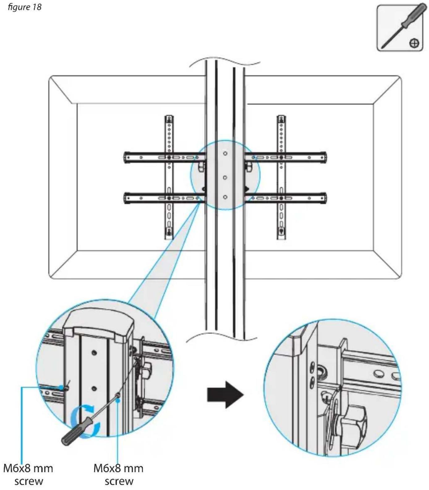
- To secure the TV in the landscape position, insert two of the M6x8 mm screws into the support plate and use a Phillips type screwdriver to tighten the screws.
(figure 18)
To move the TV into portrait orientation, see the "Change the orientation of the TV" section.
Counterbalance the weight of the TV
When you add a TV to the STNDMTV70, you need to adjust the lift capacity of the TV cart to support the weight of the TV. If the lift capacity of the STNDMTV70 isn't set correctly, when you let go of the TV, it could free fall down the column or move up the column unaided, resulting in damage to the TV or personal injury.
Warning! Counterbalancing the weight of the TV requires multiple people. Do not attempt to complete this task by yourself.
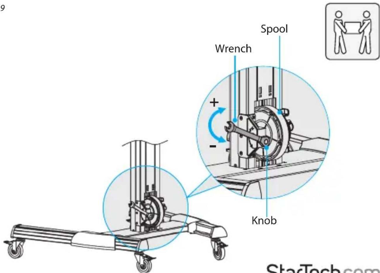
- At the bottom of the column, pull the pin out of the spool and turn it to the unlocked position.
-
Move the TV up the column a short distance and loosen your hold on the TV to see if it remains stationary. Based on what you observe, do one of the following:
-
If the TV rises up the column, use the wrench to turn the knob near the spool clockwise. (figure 19)
- If the TV falls down the column, use the wrench to turn the knob near the spool counterclockwise. (figure 19)
Warning! If you encounter resistance when you turn the knob, stop turning it. If you continue to turn the knob, you may damage the TV cart.
Note: To counterbalance the weight of the TV, you may need to turn the knob near the spool up to 80 full revolutions.
figure 19
- Repeat step 2 until the weight of the TV is counterbalanced.
Note: When the weight of the TV is properly counterbalanced, the TV will remain stationary on the column when you loosen your hold on it, and you will be able to move the TV up or down the column with minimal effort.
-
When the weight of the TV is counterbalanced, move the TV to the desired height.
-
Pull the pin and turn it to the locked position.
-
To make sure that the pin is properly aligned in one of the holes in the spool, pull up or push down on the TV. You may hear a clicking sound as the spring-loaded pin goes into a hole and prevents the spool from rotating.
When the pin is aligned in one of the holes and the TV is locked in a vertical position, the TV shouldn't move when you pull up or push down on it.
Caution! If the pin is misaligned and isn't fully inserted into one of the holes on the spool, the vertical position isn't locked and the TV could free fall down the column or spring upwards, resulting in damage to the TV or personal injury.
Warning! The degree of the lift strength that you set the STNDMTV70 to depends upon the weight of the TV. Every time that you take a TV off of the STNDMTV70 and add a different TV, you must counterbalance the weight of the TV again.
Attach the plastic cover
Caution! Exercise caution when you assemble the plastic cover because the tabs on the plastic cover can be broken off easily if you use excess force during assembly.
- Carefully separate the two halves of the plastic cover. (figure 20)
figure 20
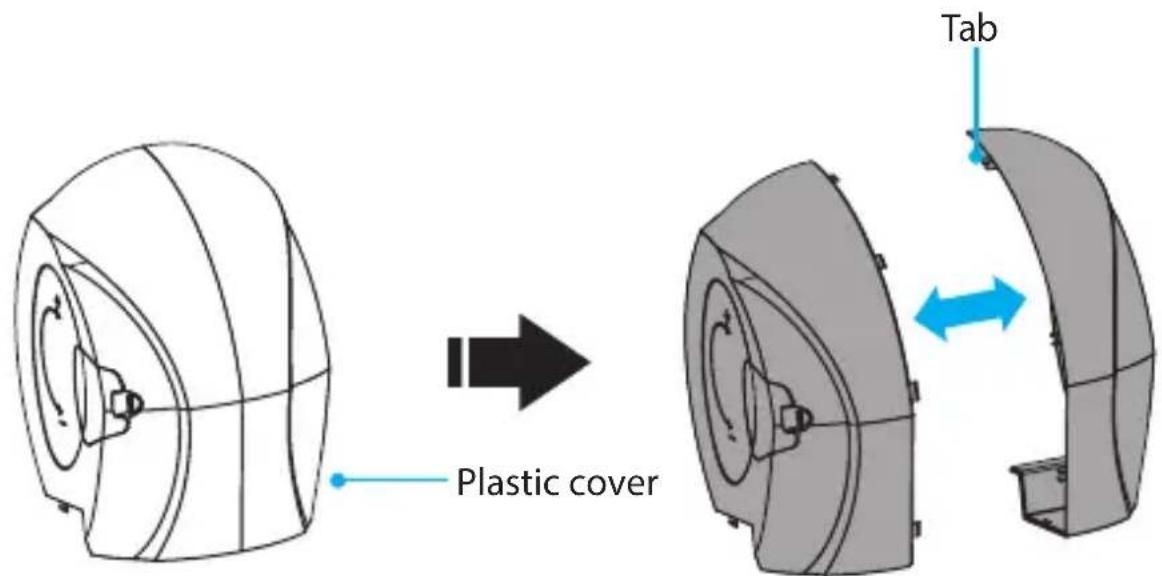
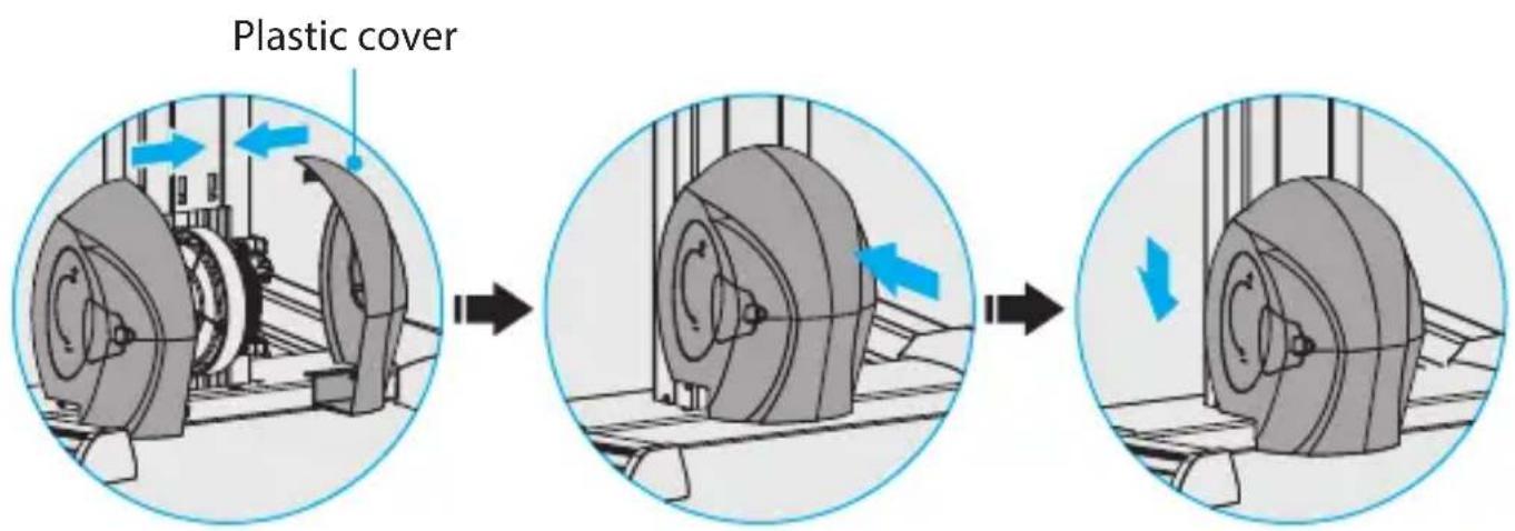
- Place the two halves of the plastic cover around the spool and snap the two sides together.
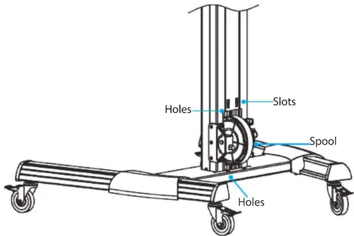
- Move the assembled plastic cover in towards the column and carefully hook the tabs on the top of the plastic cover into the slots on the column.
- Press the plastic cover down towards the base and snap the tabs on the plastic cover into the holes on the column and the base. (figure 21)
figure 21
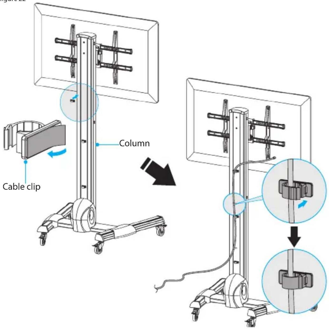
Attach the cable clips
- Remove the backing from the cable clips.
- Attach the cable clips along the column.
- Route the cables down the column and through the cable clips.
- Snap the cable clips closed. (figure 22)
figure 22
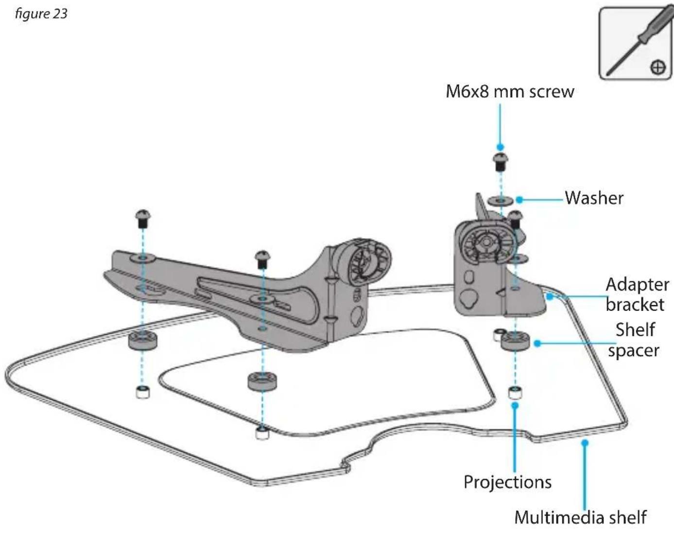
Install the multimedia shelf
- Place the shelf spacers over the projections on the underside of the multimedia shelf.
- Position the right and left support brackets over the washers so that the holes are aligned and the scalloped edges of the adapter brackets are pointed towards the outside edges of the multimedia shelf.
- Place the washers over the holes in the adapter brackets, and insert the M6x8 mm screws through the washers, adapter brackets, and into the projections on the multimedia shelf.
- Use a Phillips type screwdriver to tighten the M6x8 mm screws. (figure 23)
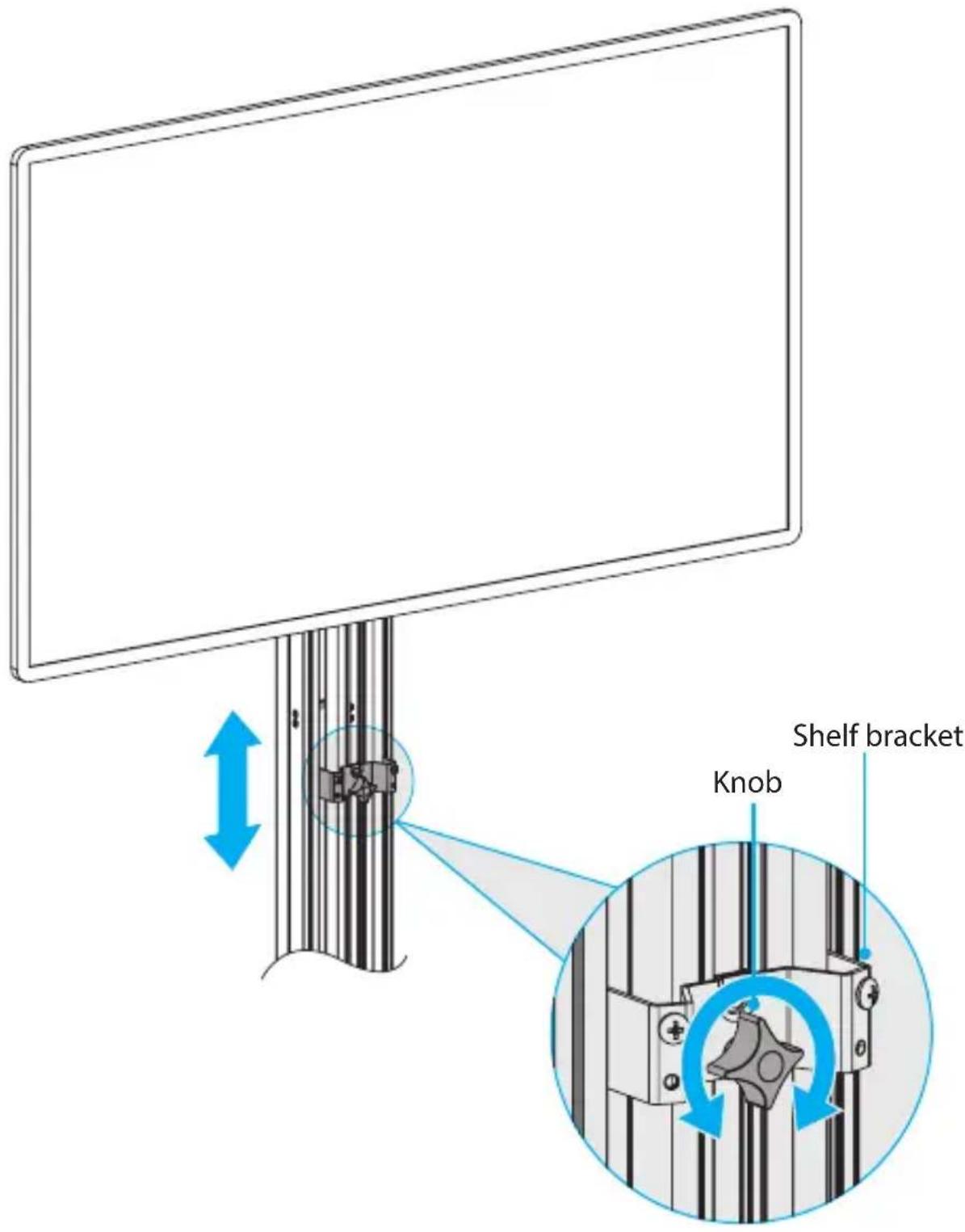
-
Turn the knob on the shelf bracket counterclockwise to loosen it.
-
Move the shelf bracket to the height that you want the multimedia shelf to be at, and turn the knob clockwise to tighten it. (figure 24)
figure 24
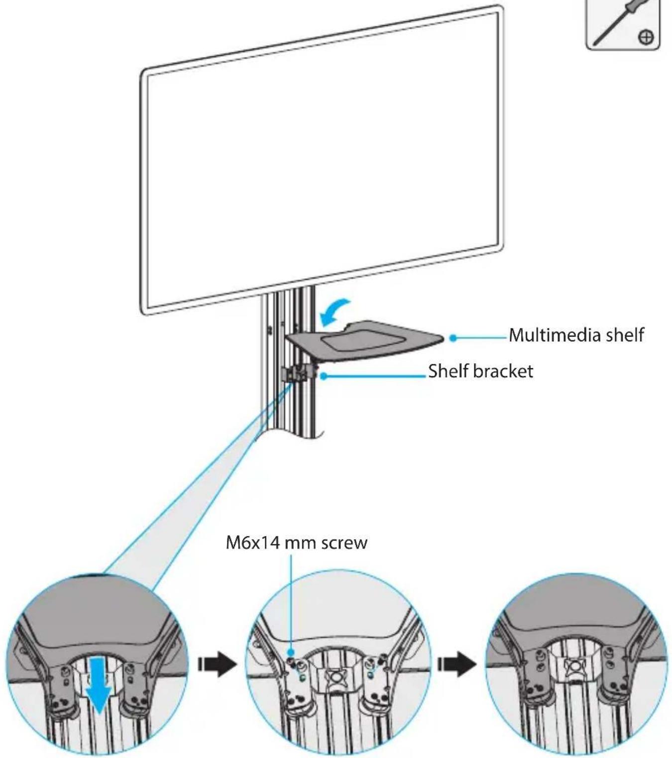
- Hook the multimedia shelf over the screws in the shelf bracket and slide the multimedia shelf downwards.
- Insert two M6x14 mm screws into the multimedia shelf and into the shelf bracket.
- Use a Phillips type screwdriver to tighten all four of the M6x14 mm screws. (figure 25)
figure 25
Attach the camera shelf
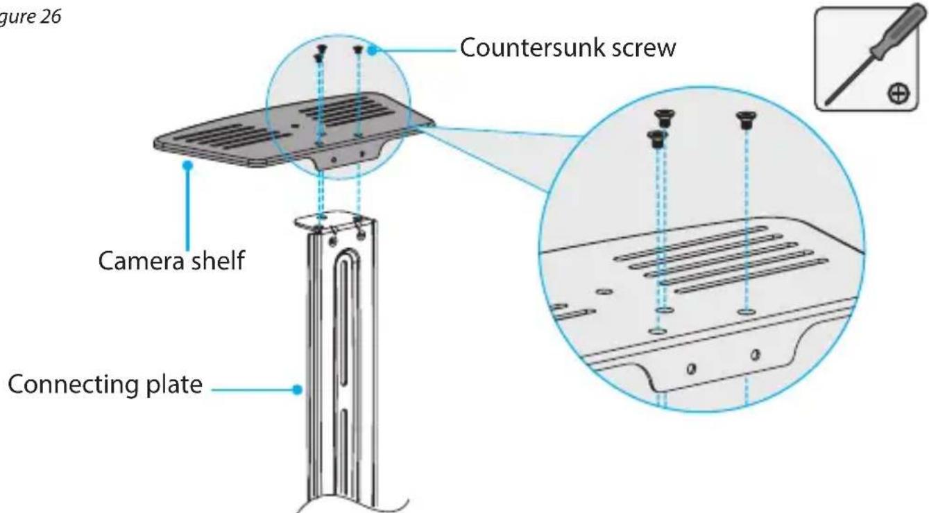
- Line up the holes on the camera shelf with the holes on the end of the connecting plate.
- Insert the three countersunk screws through the top of the camera shelf and into the connecting plate.
- Use a Phillips type screwdriver to tighten the countersunk screws. (figure 26)
figure 26
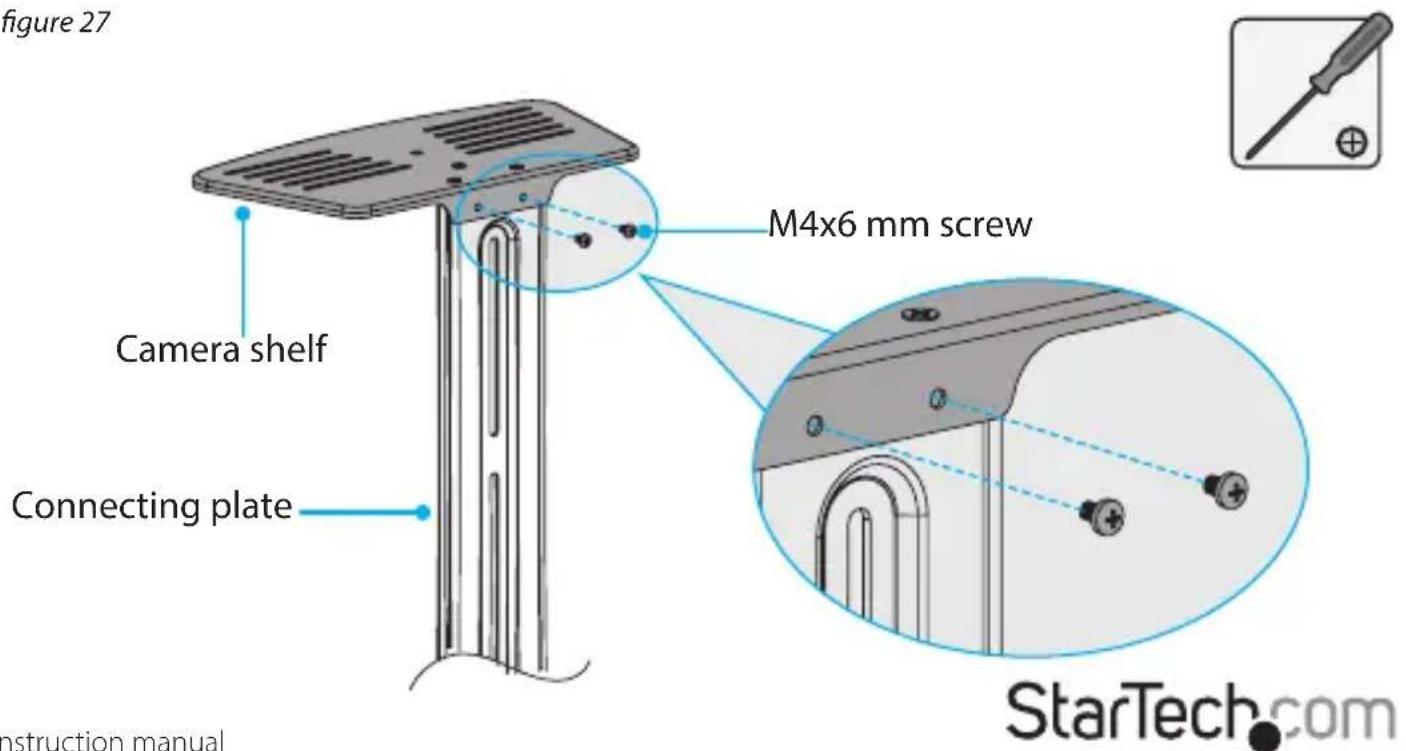
- Insert the two M4x6 mm screws into the camera shelf and into the side of the connecting plate. (figure 27)
- Use a Phillips type screwdriver to tighten the screws in place.
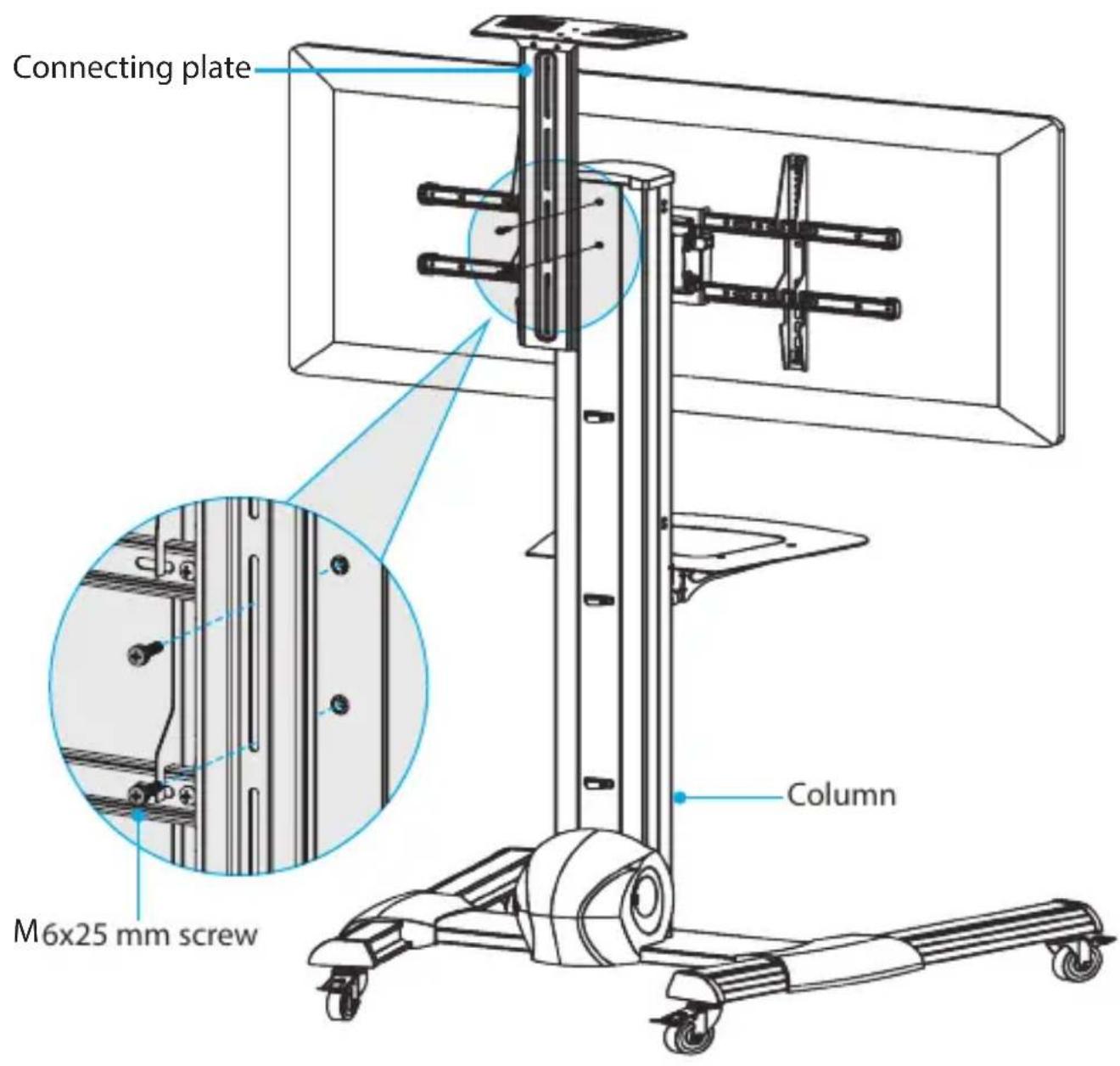
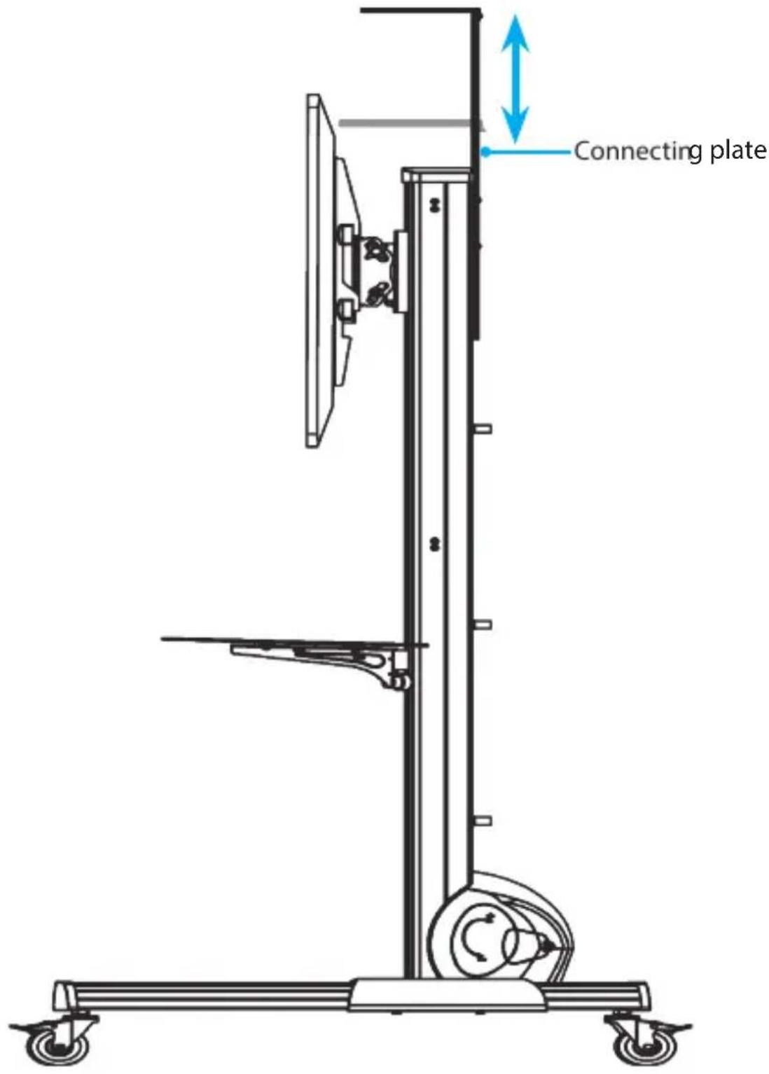
- Determine the height that you want the camera shelf to be at and line it up with the mounting slots on the back of the column.
- Insert the two M6x25 mm screws through the connecting plate and into the column. (figure 28)
- Use a Phillips type screwdriver to tighten the screws in place.
figure 28
Attach the wrench
-
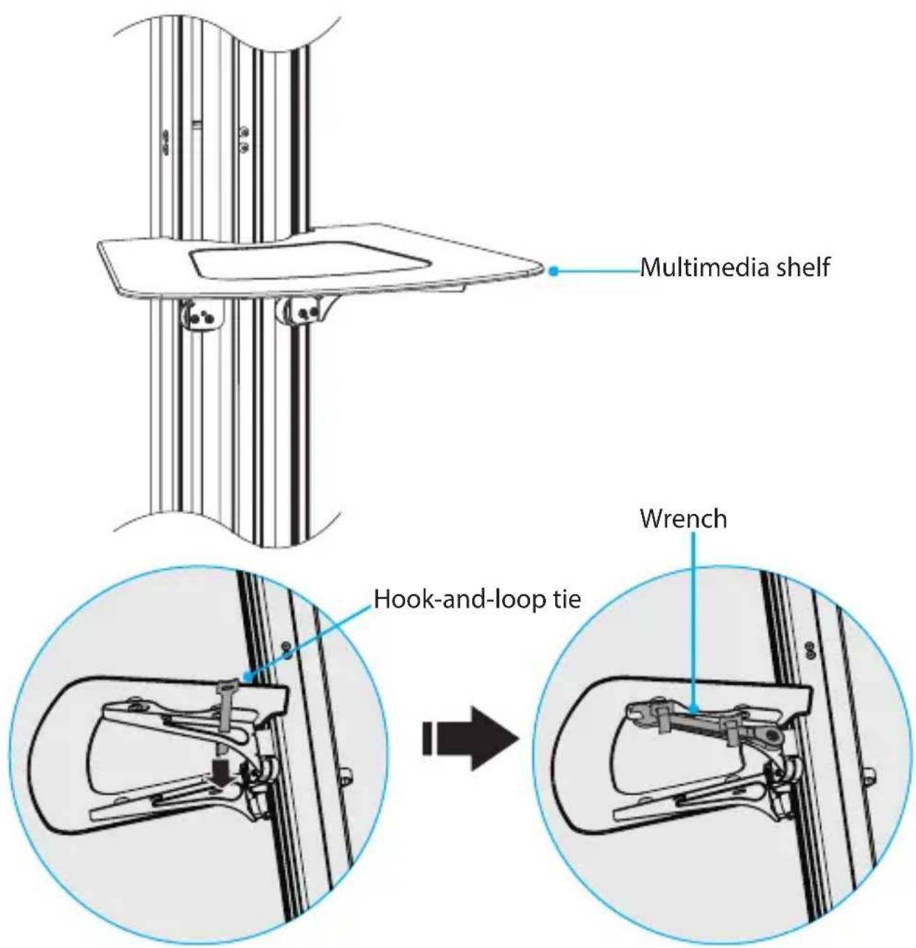
Thread the two hook-and-loop ties through the hole in one of the support brackets under the multimedia shelf.
-
Hold the wrench against the support bracket and wrap the hook-and-loop ties around the wrench. (figure 29)
figure 29
Adjusting the STNDMTV70
Change the orientation of the TV
You can position the TV in either landscape or portrait orientation on the STNDMTV70.
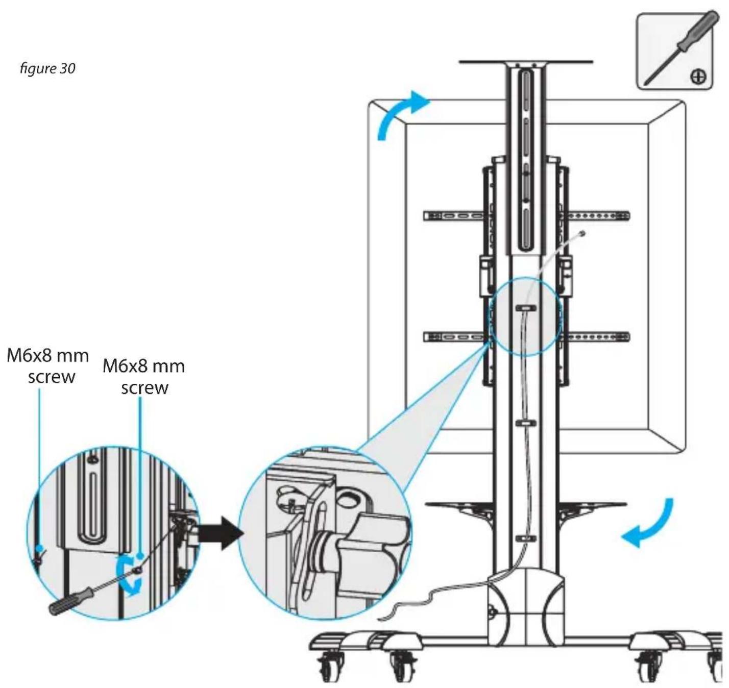
- To display the TV in portrait orientation, if present, remove the two M6x8 mm screws from the back of the support plate.
- Rotate the TV 90° clockwise.
- Reinsert the M6x8 mm screws you removed in step 1, and use a Phillips type screwdriver to tighten them. (figure 30)
Adjust the angle of the TV
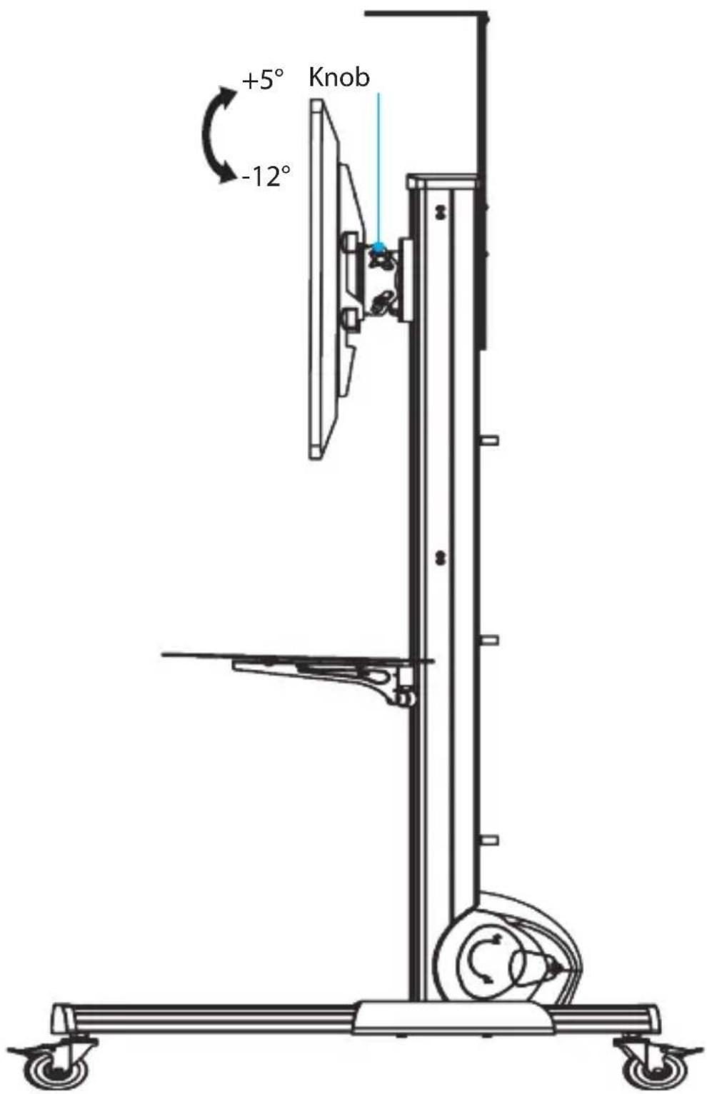
- Turn the knobs on either side of the support plate counterclockwise to loosen them.
- Push or pull the top or bottom of the TV to adjust the angle of the TV.
- Turn the knobs on either side of the support plate clockwise to tighten them. (figure 31)
figure 31
Adjust the height of the multimedia shelf
-
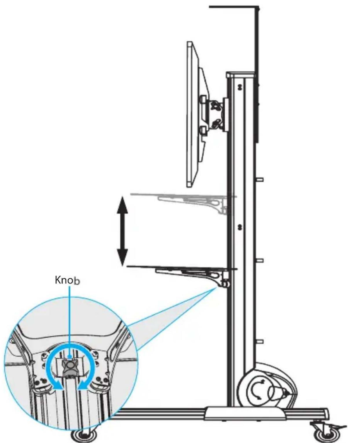
Under the multimedia shelf, turn the knob counterclockwise.
-
Move the multimedia shelf to the desired height, and turn the knob clockwise to tighten it into place. (figure 32)
figure 32
Adjust the height of the camera shelf
- Loosen the two M6x25 mm screws attaching the connecting plate to the column.
- Move the connecting plate to the desired height, and use a Phillips type screwdriver to tighten the M6x25 mm screws into place. (figure 33)
figure 33
Lock the vertical position of the TV
When the TV is at the height that you want it to be at, you should lock the vertical position of the TV to prevent the TV from moving up or down the column.
Warning! Exercise caution when you pull the pin out of the spool and turn it to the unlocked position. The weight of the TV may not be counterbalanced and the TV could free fall down the column or spring upwards, resulting in damage to the TV or personal injury.
- Pull the pin out of the spool and turn it to the unlocked position.
- If necessary, adjust the height of the TV.
- Pull the pin and turn it to the locked position.
- To make sure that the pin is properly aligned in one of the holes in the spool, pull up or push down on the TV. You may hear a clicking sound as the spring-loaded pin goes into the hole and prevents the spool from rotating.
When the pin is aligned in one of the holes and the TV is locked in a vertical position, the TV shouldn't move when you pull up or push down on it.
Caution! If the pin is misaligned and isn't fully inserted into one of the holes on the spool, the vertical position isn't locked and the TV could free fall down the column or spring upwards, resulting in damage to the TV or personal injury.
- Close the door on the plastic cover.
Technical support
StarTech.com's lifetime technical support is an integral part of our commitment to provide industry-leading solutions. If you ever need help with your product, visit www.startech.com/support and access our comprehensive selection of online tools, documentation, and downloads.
For the latest drivers/software, please visit www.startech.com/downloads
Warranty information
This product is backed by a five-year warranty.
StarTech.com warrants its products against defects in materials and workmanship for the periods noted, following the initial date of purchase. During this period, the products may be returned for repair, or replacement with equivalent products at our discretion. The warranty covers parts and labor costs only. StarTech.com does not warrant its products from defects or damages arising from misuse, abuse, alteration, or normal wear and tear.
Limitation of liability
In no event shall the liability of StarTech.com Ltd. and StarTech.com USA LLP (or their officers, directors, employees or agents) for any damages (whether direct or indirect, special, punitive, incidental, consequential, or otherwise), loss of profits, loss of business, or any pecuniary loss, arising out of or related to the use of the product exceed the actual price paid for the product. Some states do not allow the exclusion or limitation of incidental or consequential damages. If such laws apply, the limitations or exclusions contained in this statement may not apply to you.
Hard-to-find made easy. At StarTech.com, that isn't a slogan. It's a promise.
StarTech.com is your one-stop source for every connectivity part you need. From the latest technology to legacy products — and all the parts that bridge the old and new — we can help you find the parts that connect your solutions.
We make it easy to locate the parts, and we quickly deliver them wherever they need to go. Just talk to one of our tech advisors or visit our website. You'll be connected to the products you need in no time.
Visit www.startech.com for complete information on all StarTech.com products and to access exclusive resources and time-saving tools.
StarTech.com is an ISO 9001 registered manufacturer of connectivity and technology parts since 1985 with operations around the world.
Reviews
Share your experiences using StarTech.com products, including product applications and setup, what you love about the products, and areas for improvement.
StarTech.com Ltd.
45 Artisans
Crescent
London, Ontario
N5V 5E9
Canada
StarTech.com LLP
4490 South
Hamilton Road
Groveport, Ohio
43125
U.S.A.
StarTech.com Ltd.
Unit B, Pinnacle 15
Gowerton Road
Brackmills,
Northampton
NN4 7BW
United Kingdom
StarTech.com Ltd.
Siriusdreef 17-27
2132 WT
Hoofddorp
The Netherlands
FR: fr.startech.com
DE: de.startech.com
ES: es.startech.com
NL: nl.startech.com
IT: it.startech.com
JP: jp.startech.com
- Mobile Media Center for Flat-Screen TV - One-Touch Height Adjustment
- Use of Trademarks, Registered Trademarks, and other Protected Names and Symbols
- Warning statements
- Varningsmeddelanden
- Assembly....11
- Adjusting the STNDMTV70....39
- Technical support....44
- Warranty information....44
- Introduction Product dimensions
- Product diagram
- Technical specifications
- Package contents
- Requirements
- Assembly
- Assemble the base
- Adjust the height of the casters
- Attach the column to the base
- Assemble the TV mount
- Attach the support plate to the column
- Move the support plate to the lowest position
- Attach the adapter brackets to a flush mounting surface
- Attach the adapter brackets to a recessed mounting surface
- Attach the TV to the column
- Counterbalance the weight of the TV
- Attach the plastic cover
- Attach the cable clips
- Install the multimedia shelf
- Attach the camera shelf
- Attach the wrench
- Adjusting the STNDMTV70
- Change the orientation of the TV
- Adjust the angle of the TV
- Adjust the height of the multimedia shelf
- Adjust the height of the camera shelf
- Lock the vertical position of the TV
- Technical support
- Warranty information
- Limitation of liability
- Hard-to-find made easy. At StarTech.com, that isn't a slogan. It's a promise.
- Reviews
- StarTech.com Ltd.
- StarTech.com LLP
Brand : StarTech.com
Model : STNDMTV70
Category : Wall mount