AXPIO-CAM2 - Unknown AXESS - Free user manual and instructions
Find the device manual for free AXPIO-CAM2 AXESS in PDF.

User questions about AXPIO-CAM2 AXESS
0 question about this device. Answer the ones you know or ask your own.
Ask a new question about this device
Download the instructions for your Unknown in PDF format for free! Find your manual AXPIO-CAM2 - AXESS and take your electronic device back in hand. On this page are published all the documents necessary for the use of your device. AXPIO-CAM2 by AXESS.
USER MANUAL AXPIO-CAM2 AXESS
natural_image
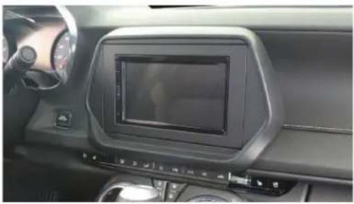
Interior view of a car dashboard with a digital display and steering wheel (no visible text or symbols)Chevrolet Camaro 2019-UP
Visit AxxessInterfaces.com for more detailed information about the product and up-to-date vehicle specific applications.
KIT FEATURES
- Designed for Pioneer DMH-WC5700NEX receivers
- Allows for the retention and adjustment of the factory personalization menu through the Pioneer radio
- Provides a visual view of HVAC and gauges on the Pioneer screen (can not be adjusted via the screen) (cont. on page 2)
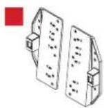
KIT COMPONENTS
- A) Display Screen Housing • B) Display Screen Trim Bezel • C) Display Screen Trim • D) Brackets • E) Panel Clips • F) Phillips Screws (4) Not Shown: Radio Interface, LD-GM30-PIO, LD-GM31-PIO, AXEXH-GM30, AXEXH-GM31 LD-GMSWC, AD-EU5, 40-GPS-PIO, PRO4AVIC-PIO / PRO4-PIORCA, LD-AX-SPK, AXUSB-GM6

natural_image
Technical line drawing of a mechanical housing or enclosure component (no text or symbols)
natural_image
Isometric line drawing of a 3D rectangular prism with no text or symbols

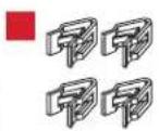
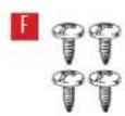
TABLE OF CONTENTS
Interface Installation 2
Dash Disassembly 2-3
Connections....4-5
Kit Assembly 6
Radio Operations....7-8
WIRING & ANTENNA CONNECTIONS
- RGB Extension Cable: Pioneer part # CD-RGB150A (not sold by Metra)
TOOLS REQUIRED
• Panel removal tool • Phillips screwdriver
- 9/32" socket wrench
ATTENTION: With the key out of the ignition, disconnect the negative battery terminal before installing this product. Ensure that all installation connections, especially the air bag indicator lights, are plugged in before reconnecting the battery or cycling the ignition to test this product.
NOTE: Refer also to the instructions included with the aftermarket accessory before installing this device.
KIT FEATURES (CONT.)
KIT FEATURES (cont. from cover)
- Complete Plug-n-Play installation
- Includes dash kit with Axxess interface and vehicle-specific T-harness
- Includes a 3' USB/AUX/HDMI replacement cable with panel
• Includes radio antenna adaptor for GPS - Provides accessory power (12-volt 10-amp)
-
Provides NAV outputs (parking brake, reverse, speed sense)
-
Retains audio controls on the steering wheel
• Works in both single and dual-zone vehicles - Retains safety chimes through an included off-board speaker
- USB Micro B updatable
- Dash kit is painted scratch-resistant matte black to match the factory finish
- Designed for non-amplified vehicles only
DASH DISASSEMBLY
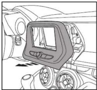
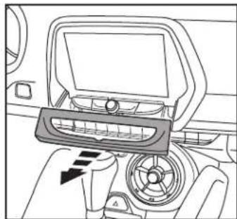
Models equipped with a 7-inch touchscreen radio:
- Using the panel removal tool, gently unclip, unplug, and remove the radio control trim panel. (Figure A)
- Remove (4) 9/32" screws securing the radio, disconnect the wiring, and then remove the radio. (Figure B)
Continue to Connections
natural_image
Technical line drawing of a vehicle dashboard with control panel and wheel (no text or symbols)(Figure A)
natural_image
Top-down technical diagram of a car's front dashboard and rear wheels (no text or symbols)(Figure B)
DASH DISASSEMBLY(CONT.)
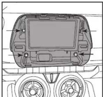
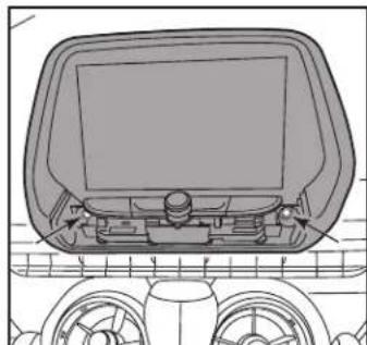
Models equipped with an 8-inch touchscreen radio:
- Using the panel removal tool, carefully unclip and remove the trim surrounding the radio controls. (Figure C)
- Remove (2) 9/32" screws securing the radio, disconnect the wiring, and then remove the radio. (Figure D)
Continue to Connections
natural_image
Interior view of a car dashboard with steering wheel and air vent (no text or symbols visible)(Figure C)
natural_image
Top-down technical diagram of a vehicle dashboard and steering wheel (no text or symbols)(Figure D)
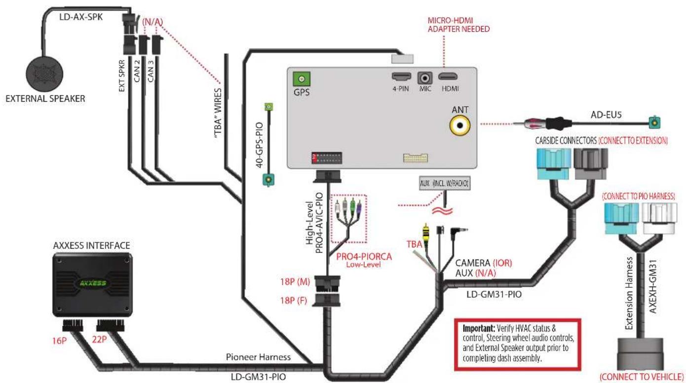
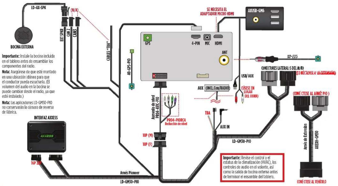
CONNECTIONS

text_image
LD-AX-SPK (N/A) EXT SPKR CAN2 CAN3 "TBA" WIRES 40-GPS-PIO GPS 4-PIN MIC HDMI ANT PRO4-PIORCA Low-Level High-Level PRO4-AVIC-PIO 18P (M) 18P (F) Pioneer Harness LD-GM30-PIO AFFSIDE CONNECTORS (CC NNBCT TO EXTENSION) LAUX (NCL W/RADIO) TBA AUX IN LD-GM30-PIO ACCENT TO VEHICLE AXXESS INTERFACE 16P 2HP EXTERNAL SPEAKER Important: Install the provided speaker in the dash prior to assembling the radio components. Note: Make sure this is mounted in a location suitable for the driver to hear. (Audio level for the speaker can be changed via the radio, once installed.) Note: LD-GM30-PIO Applications will not retain the factory backup camera. Important: Verify HVAC status & control, Steering wheel audio controls, and External Speaker output prior to completing dash assembly.CONNECTIONS (CONT.)
flowchart
graph TD
    A["AXXESS INTERFACE"] -->|16P 22P| B["Pioneer Harness"]
    B --> C["LD-GM31-PIO"]
    C --> D["PRO4-PIORCA Low-Level"]
    D --> E["GPS"]
    E --> F["ANT"]
    F --> G["AD-EU5"]
    G --> H["CARSIDE CONNECTORS (CONNECT TO EXTENSION)"]
    H --> I["(CONNECT TO PIO HARNESS)"]
    I --> J["EXTERNAL SPEAKER"]
    C --> K["LD-GM31-PIO"]
    K --> L["EXTRIOR SPKR"]
    L --> M["EXTRIOR SPK"]
    M --> N["(N/A)"]
    N --> O["TBA" WIRES"]
    O --> P["40-GPS-PIO"]
    P --> Q["High-Level PRO4-AVIC-PIO"]
    Q --> R["PRO4-PIORCA Low-Level"]
    R --> S["TBA"]
    S --> T["CAMERA (IOR) AUX (N/A)"]
    T --> U["LD-GM31-PIO"]
    U --> V["(CONNECT TO VEHICLE)"]
    style A fill:#f9f,stroke:#333
    style B fill:#ccf,stroke:#333
    style C fill:#cfc,stroke:#333
    style D fill:#fcc,stroke:#333
    style E fill:#cff,stroke:#333
    style F fill:#ffc,stroke:#333
    style G fill:#fcf,stroke:#333
    style H fill:#cff,stroke:#333
    style I fill:#ffc,stroke:#333
    style J fill:#cfc,stroke:#333
    style K fill:#fcc,stroke:#333
    style L fill:#ffc,stroke:#333
    style M fill:#cfc,stroke:#333
    style N fill:#fcc,stroke:#333
    style O fill:#ffc,stroke:#333
    style P fill:#cfc,stroke:#333
    style Q fill:#fcc,stroke:#333
    style R fill:#ffc,stroke:#333
    style S fill:#cfc,stroke:#333
    style T fill:#fcc,stroke:#333
    style U fill:#ffc,stroke:#333
    style V fill:#cfc,stroke:#333
    style_W["N/A"] -.-> X["EXTRIOR SPKR"]
    X --> Y["EXTRIOR SPK"]
    Y --> Z["EXTRIOR SPK"]
    Z --> AA["EXTRIOR SPK"]
    AA --> AB["EXTRIOR SPK"]
    AB --> AC["EXTRIOR SPK"]
    AC --> AD["EXTRIOR SPK"]
    AD --> AE["EXTRIOR SPK"]

    subgraph Legend
        direction TB
        AF["Important: Verify HVAC status & control, Steering wheel audio controls, and External Speaker output prior to completing dash assembly."]
        AG["(CONNECT TO VEHICLE)"]
        AH["AD-EU5"]
        AI["CARSIDE CONNECTORS (CONNECT TO EXTENSION)"]
        AJ["(CONNECT TO PIO HARNESS)"]
        AK["Extension Harness"]
        AL["AXEXH-GM31"]
REV. 7/25/24 INSTAXPIO-CAM2
KIT ASSE MB LY
- Secure the display screen housing to the dash using the (4) 9/32" factory screws removed in dash disassembly. (Figure A)
Note: For vehicles equipped with an 8-inch touchscreen radio, remove (2) 9/32" screws from the dash beforehand.
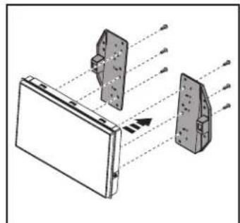
- Remove the locator pins stamped "8" from the display screen brackets. Using the holes stamped "7", secure the display screen to the brackets using (6) screws supplied with the radio. (Figure B)
Note: Reference the installation manual provided with the radio for which hardware to use. The display screen and radio chassis use two different types of screws.
- Find a suitable location for the radio chassis. Route the RGB extension cable from the radio chassis to the display screen, then connect it to the display screen.

natural_image
Technical diagram of a vehicle chassis with internal components and mounting points (no text or labels)(Figure A) (Figure C)
natural_image
Technical diagram of a mechanical assembly with labeled components and an arrow indicating direction (no text or symbols present)(Figure B) (Figure D)
-
Place the display screen trim over the bracket/display assembly, then secure the assembly to the display screen housing using (4) Phillips screws provided. (Figure C)
-
Locate the factory wiring harness and antenna connector in the dash and complete all necessary connections to the radio assembly. Metra recommends using the proper mating adapter from Metra and/or Axxess.
-
Reconnect the negative battery terminal and test the Pioneer radio for proper operation.
-
Attach (6) panel clips provided onto the display screen trim bezel, then clip the bezel over the radio to complete the installation. (Figure D)

text_image
Technical diagram showing a car interior with a monitor and dashboard, annotated with component labels like 'D1', 'D2', and 'D3'.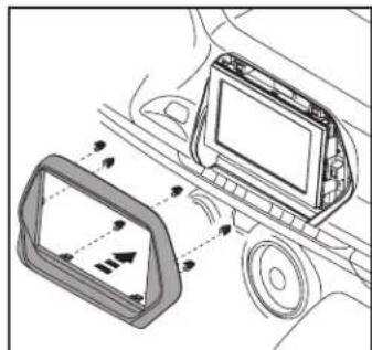
natural_image
Diagram of a car interior showing airflow or movement between a device and a vehicle (no text or symbols present)RADIO OPERATIONS
Vehicle Selection
- Allows the selection of the vehicle the Pioneer radio is being installed in.
- Select Make, Model and Trim to activate the extended functions of the radio.
- Press Confirm to lock in the selection.
- The vehicle type must be selected to activate HVAC functions and steering wheel controls.

text_image
Vehicle Selection Make No Selection Model Trim Save to Flash and Restart Confirm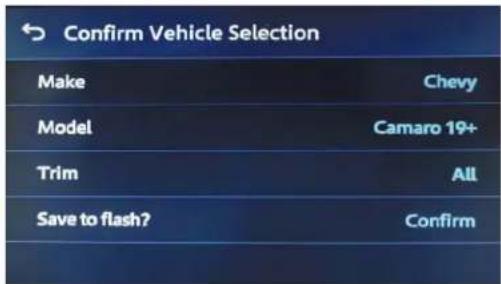
text_image
Confirm Vehicle Selection Make Chevy Model Camaro 19+ Trim All Save to flash? ConfirmCar Features
The source for accessing all vehicle information and options.

text_image
Car Features HD Radio Bluetooth Audio iPod Browser AUX
text_image
HD Radio Bluetooth Audio USB iPod WiFi Audio HDMI SonicOMI AUX Car Features Camera View Phone Settings Dimmer Drop OFF No Device Alexa Browser Sports Weather No Device Connectivity CarAVAssistRADIO OPERATIONS (CONT.)
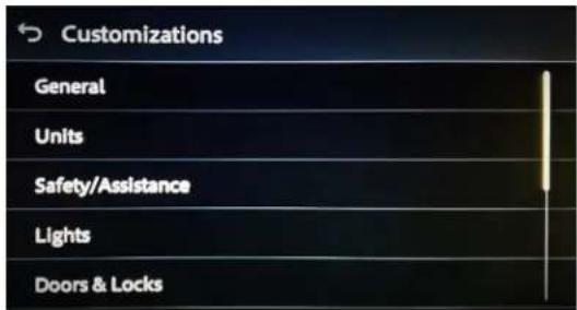
Customizations Menu : Allows full control of vehicle personalization options.
Access this menu by selecting the gear icon on the previous screenshot:
- Provides SWC Configuration.
- Dual Assignment: Assign (2) functions to a single SWC button.
- Remap: Reassign a button on the steering wheel controls.
text_image
Customizations General Units Safety/Assistance Lights Doors & LocksHVAC Operation: HVAC Status and Control Screen

text_image
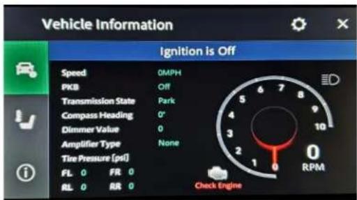
Climate -60°F 59°F 59°F Auto Sync Dual A/C Max A/CVehicle Information Screen : The source for accessing all vehicle information and options.
text_image
Vehicle Information Ignition is Off Speed DMPH PKB Off Transmission State Park Compass Heading 0° Dimmer Value 0 Amplifier Type None Tire Pressure (psi) FL 0 FR 0 RL 0 RR 0 Check EngineAbout Screen: Feedback screen for interface software information.
• Helpful information for troubleshooting.

text_image
Metra Information Interface HW Version: D Interface FW Version: B.56
AXPIO-CAM2 INSTALLATION INSTRUCTIONS

Having difficulties? We're here to help.
Contact our Tech Support line at: 386-257-1187
Or via email at: techsupport@metra-autosound.com
Tech Support Hours (Eastern Standard Time)
Monday - Friday: 9:00 AM - 7:00 PM
Saturday: 10:00 AM - 5:00 PM
Sunday: 10:00 AM - 4:00 PM

Metra recommends MECP certified technicians
natural_image
Interior view of a car dashboard with a digital display and steering wheel (no visible text or symbols)Chevrolet Camaro 2019-Más
natural_image
Technical line drawing of a mechanical component with no visible text or symbols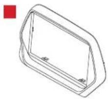
natural_image
Isometric line drawing of a 3D rectangular prism with no text or symbols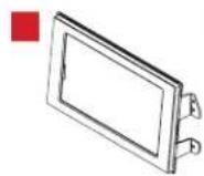


ÍNDICE
natural_image
Technical line drawing of a vehicle dashboard and steering wheel assembly (no text or symbols)(Figura A)

natural_image
Top-down technical diagram of a car's front dashboard and steering wheel (no text or labels)(Figura B)
DESARMADO DEL TABLERO (CONT.)
natural_image
Interior view of a car dashboard with steering wheel and air vent (no text or symbols visible)(Figura C)

natural_image
Top-down technical diagram of a vehicle dashboard and steering wheel (no text or symbols)(Figure D)
CONEXIONES
natural_image
Technical diagram of a vehicle chassis showing internal components and mounting points (no text or labels)(Figura A) (Figura C)

natural_image
Technical diagram showing two mechanical components with alignment lines and an arrow indicating direction (no text or symbols present)(Figura B) (Figura D)
text_image
Technical diagram showing car interior components with labeled parts and directional arrows indicating movement or assembly.
natural_image
Diagram of a car interior showing airflow or movement between a device and a vehicle (no text or symbols present)text_image
Vehicle Selection Make No Selection Model Trim Save to Flash and Restart Confirm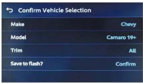
text_image
Confirm Vehicle Selection Make Chevy Model Camaro 19+ Trim All Save to flash? Confirmtext_image
HD Radio Bluetooth Audio USB iPod WiFi Audio HDMI Sens\\MM AUX Car Features Camera View Phone Settings Dimmer Drop OFF No Device Alexa Browser Sports Weather No Device Connectivity CarAVAssistOPERACIONES DEL RADIO (CONT.)
text_image
Customizations General Units Safety/Assistance Lights Doors & Lockstext_image
Vehicle Information Ignition is Off Speed 0MPH PKB Off Transmission State Park Compass Heading 0° Dimmer Value 0 Amplifier Type None Tire Pressure (ptl) FL 0 FR 0 RL 0 RR 0 Check Enginetext_image
Metra Information Interface HW Version: D Interface FW Version: B.56