AXPIO-SIL1 - Unknown AXESS - Free user manual and instructions
Find the device manual for free AXPIO-SIL1 AXESS in PDF.

User questions about AXPIO-SIL1 AXESS
0 question about this device. Answer the ones you know or ask your own.
Ask a new question about this device
Download the instructions for your Unknown in PDF format for free! Find your manual AXPIO-SIL1 - AXESS and take your electronic device back in hand. On this page are published all the documents necessary for the use of your device. AXPIO-SIL1 by AXESS.
USER MANUAL AXPIO-SIL1 AXESS
natural_image
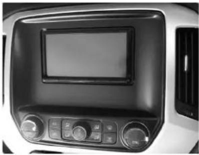
Interior view of a car air conditioner unit with digital display and control knobs (no visible text or symbols)Chevrolet Silverado/GMC Sierra 2014-2019 (excluding 2019 WT Trim) with RPO (I05/I06/I0B)
Visit AxxessInterfaces.com for more detailed information about the product and up-to-date vehicle specific applications.
KIT FEATURES)
- Designed for Pioneer DMH-W4600NEX/W4660NEX or DMH-WC5700NEX receivers
- Allows for the retention and adjustment of the factory personalization menu through the Pioneer radio
- Provides a visual view of HVAC and gauges on the Pioneer screen (cannot be adjusted via the screen) (cont. on page 2)
KIT COMPONENTS
• A) Radio trim panel • B) Radio brackets • C) Phillips screws 9/32" (4)
Not Shown: Radio Interface, LD-GMLAN09-PIO, LD-GMLAN10-PIO, AXEXH-GM09, AXEXH-GM10, LD-BACKCAM-MOST, LD-GMSWC, AD-EU5, 40-GPS-PIO, PR04AVIC-PIO / PR04-PIORCA, LD-AX-SPK, AXUSB-GM6
AB
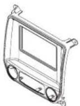
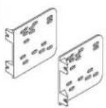
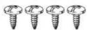
TABLE OF CONTENTS
Speaker Installation....2
Dash Disassembly....2-3
Kit Preparation....4
Connections....5-6
Kit Assembly 7
Radio Operations....8-9
WIRING & ANTENNA CONNECTIONS (sold separately)
- RGB Extension Cable: Pioneer part # CD-RGB150A (not sold by Metra)
TOOLS REQUIRED
- Panel removal tool • Phillips screwdriver
- 9/32" socket wrench
ATTENTION: With the key out of the ignition, disconnect the negative battery terminal before installing this product. Ensure that all installation connections, especially the air bag indicator lights, are plugged in before reconnecting the battery or cycling the ignition to test this product.
NOTE: Refer also to the instructions included with the aftermarket radio.
KIT FEATURES (CONT.)
KIT FEATURES (cont. from cover)
- Complete Plug-n-Play installation
- Includes dash kit with Axxess interface and vehicle-specific T-harness
- Includes a 3' USB/AUX/HDMI replacement cable with panel
- Includes radio antenna adaptor for GPS
- Provides accessory power (12-volt 10-amp)
-
Provides NAV outputs (parking brake, reverse, speed sense)
-
Retains audio controls on the steering wheel
• Works in both single and dual-zone vehicles - Retains safety chimes through an included off-board speaker
- USB Micro "B" USB updatable
- Dash kit is painted scratch-resistant matte black to match the factory finish
- For non-amplified vehicles only
SPEAKER INSTALLATION
Install the provided speaker in the dash prior to assembling the radio components.
Note: Make sure this is mounted in a location suitable for the driver to hear. (Audio level for the speaker can be changed via the radio, once installed.)
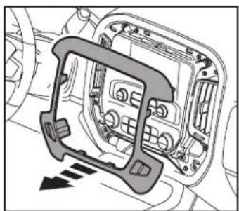
DASH DISASSEMBLY
- Using the panel removal tool, carefully unclip and remove the radio/climate control trim panel. (Figure A)
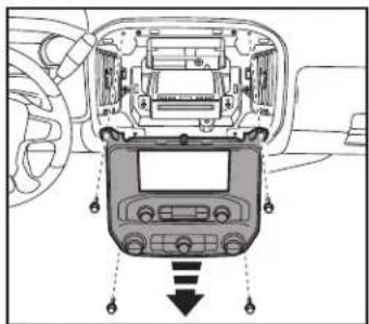
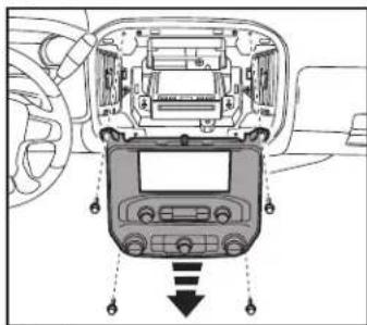
- Remove (4) 9/32" screws securing the radio/climate control panel, then unclip, unplug and remove the panel. (Figure B)
natural_image
Diagram of a car interior showing dashboard and airway components (no text or labels)(Figure A)
text_image
Diagram showing car dashboard and infotainment device with Chinese labels and directional arrows indicating signal flow.(Figure B)
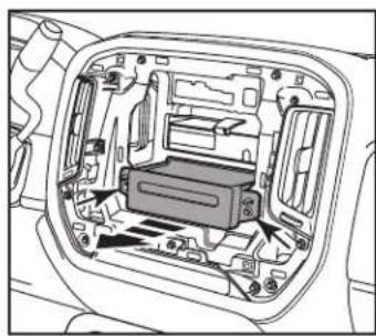
DASH DISASSEMBLY (CONT.)
- Remove (2) 9/32" screws securing the CD player. Slide the CD player out, then unplug and remove the CD player. (Figure C)
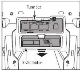
- Unclip and slide out the Onstar module and tuner box, then unplug and remove them. (Figure D)
natural_image
Technical diagram of a car interior showing internal components (no text or labels)(Figure C)
text_image
Tuner box Onstar module(Figure D)
If using the LD-LAN09-PIO:
- Using the panel removal tool, unclip the plastic shroud around the steering wheel column. (Figure E)
- Connect the LD-GMSWC to the 10-pin straight row connector located in the steering column.
- Route the LD-GMSWC cable through the steering column into the dash and back towards the radio area.
- Remove (3) bolts from the lower trim cover. Rotate the steering wheel to gain access to the bolts, then remove the forward facing bolts. (Figure F)
NOTE: If RPO is 105 or 106, use the LD-LAN09-PIO. If RPO is 10B, use the LD-LAN10-PIO.

natural_image
Technical line drawing of a mechanical component with no visible text or symbols(Figure E)
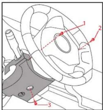
text_image
Technical diagram of a mechanical component with numbered parts and red annotation lines(Figure F)
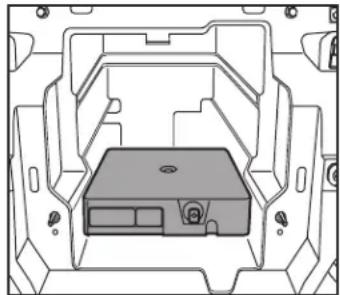
KIT PREPARATION
- Cut the sub-dash to allow room for the aftermarket radio. (Figure A)
- Relocate the OnStar module lower in the sub-dash where the factory CD player was installed to allow room for the aftermarket radio. (Figure B)
Continue to Kit Assembly

natural_image
Technical line drawing of a mechanical assembly with no visible text or symbols(Figure A)
natural_image
Technical line drawing of a mechanical housing or enclosure with internal components (no text or symbols)(Figure B)
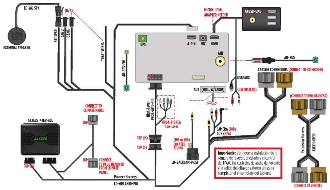
CONNECTIONS

flowchart
graph TD
    A["LD-GMSWC"] --> B["LD-LAN09-P10"]
    B --> C["EXTERNAL SPEAKER"]
    C --> D["EXT SPRB"]
    D --> E["CAN2"]
    D --> F["CAN3"]
    E --> G[""TBA" WIRBS"]
    F --> G
    G --> H["GPS"]
    H --> I["4-PIN"]
    I --> J["MIC"]
    J --> K["HDMI"]
    K --> L["ANT"]
    L --> M["Micro-HDMI ADAPTER NEEDED"]
    M --> N["AXUSB-GM6"]
    N --> O["AS-205"]
    O --> P["CARSIDE CONNECT RS (CON) CT INEXTENSION"]
    P --> Q["USB/AUX (USE INSTEAD)"]
    Q --> R["AUX (INCL. W/RADIO)"]
    R --> S["PRO4-AVIC-P10"]
    S --> T["PRO4-PIORCA Low-Level"]
    T --> U["18P (M)"]
    T --> V["18P (F)"]
    U --> W["(105 or 106) LOCATED AT HMI"]
    V --> W
    W --> X["LD-BACKCAM-MOST"]
    X --> Y["CAMERA (10B) AUX (N/A)"]
    Y --> Z["ACCUM/UP PIONHARNESS"]
    Z --> AA["CON ELECTD PIOHARNESS"]
    AA --> AB["ASSA/UP PIONHARNESS"]
    AB --> AC["CON ELECTD TO VEHICLE"]
    AC --> AD["ATT/AT VEHICLE"]
    AD --> AE["NOTE: IF USING LD-LAN09-P10"]
    AE --> AF["LOCATED AT STEERING COLUMN"]
    AF --> AG["Connect TO CLIMATE PANEL"]
    AG --> AH["EXPRESS INTERFACE"]
    AH --> AI["Pioneer Harness LD-GMLAN09-P10"]
    AI --> AJ["40-GPS-P10"]
    AJ --> AK["High-Level PRO4-AVIC-P10"]
    AK --> AL["PRO4-PIORCA Low-Level"]
    AL --> AM["18P (M)"]
    AL --> AN["18P (F)"]
    AM --> AO["(105 or 106) LOCATED AT HMI"]
    AN --> AP["LD-BACKCAM-MOST"]
REV. 7/30/24 INSTAXPIO-SIL1
CONNECTIONS (CONT.)

flowchart
graph TD
    A["EXTERNAL SPEAKER"] --> B["LD-AX-SPK"]
    B --> C["EXT SPRR"]
    C --> D["CAN2"]
    C --> E["CAN3"]
    D --> F["TBA" WIRES"]
    E --> F
    F --> G["40-GPS-PIO"]
    G --> H["GPS"]
    H --> I["4-PIN"]
    H --> J["MIC"]
    H --> K["HDMI"]
    K --> L["ANT"]
    L --> M["AUX (INCL. W/RADIO)"]
    M --> N["PRO4-PIORCA Low-Level"]
    N --> O["PRO4-AVIL-PIO"]
    O --> P["16P ZIP"]
    P --> Q["Pioneer Harness"]
    Q --> R["LD-GMLANTO-PIO"]
    R --> S["AXXESS INTERFACE"]
    S --> T["CONNECT TO CLIMATE PANEL"]
    T --> U["10P"]
    U --> V["10P CONNECT TO PLUG REMOVED FROM CLIMATE PANEL"]
    V --> W["High-level PRO4-AVIL-PIO"]
    W --> X["18P (M)"]
    W --> Y["18P (F)"]
    X --> Z["(105 or 106) LOCATED AT HMI"]
    Y --> AA["LD-BACKCAM-MOST"]
    AA --> AB["CAMERA (10B) AUX (N/A)"]
    AB --> AC["USB/AUX (USE INSTEAD)"]
    AC --> AD["CARSIDE CONNECTORS (CONNECT TO EXTENSION)"]
    AD --> AE["AD-EU5"]
    AE --> AF["AXUSB-GM6"]
    AF --> AG["ACCESS CORNER"]
    AG --> AH["ATT"]
    AH --> AI["Micro-HDMI ADAPTER NEEDED"]
    AI --> AJ["LOGIC RELAYABLE SYSTEMS"]
    AJ --> AK["CONTENTS WITH CONTENTS"]
    AK --> AL["CONTENTS WITH CONTENTS"]
    AL --> AM["CONTENTS WITH CONTENTS"]
    AM --> AN["CONTENTS WITH CONTENTS"]
    AN --> AO["CONTENTS WITH CONTENTS"]
    AO --> AP["CONTENTS WITH CONTENTS"]
    AP --> AQ["CONTENTS WITH CONTENTS"]
    AQ --> AR["CONTENTS WITH CONTENTS"]
    AR --> AS["CONTENTS WITH CONTENTS"]
    AS --> AT["CONTENTS WITH CONTENTS"]
    AT --> AU["CONTENTS WITH CONTENTS"]
    AU --> AV["CONTENTS WITH CONTENTS"]
KIT ASSE MB LY
- Secure the radio brackets to the radio trim panel using the (4) #8 x 3/8" Phillips screws provided with this kit. (Figure A)
- Slide the radio between the radio brackets, then secure using screws supplied with the radio. (Figure B)
- Clip the factory climate controls into the radio trim panel. (Figure C)
- Locate the factory wiring harness and antenna connector in the dash. Metra recommends using the proper mating adapter from Metra or AXXESS.
- Complete all connections to the radio and vehicle, reconnect the negative battery terminal, and then test the Pioneer radio and vehicle for proper operation.
- Mount the radio assembly into the dash using the factory screws and reassemble the dash in the reverse order of disassembly to complete the installation.

natural_image
Technical line drawing of a car dashboard frame with no visible text or symbols
natural_image
Technical line drawing of a car dashboard with control panel and buttons (no text or symbols)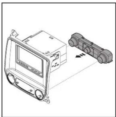
natural_image
Technical line drawing of a vehicle dashboard and two connected electrical components (no text or symbols)(Figure C)(Figure A) (Figure B)
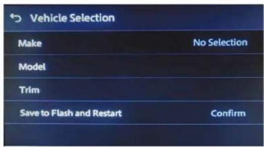
RADIO OPERATIONS
Vehicle Selection
- Allows the selection of the vehicle the Pioneer radio is being installed in.
- Select Make, Model and Trim to activate the extended functions of the radio.
- The vehicle type must be selected to activate iPod, Bluetooth, backup cameras, as well as HVAC functions and steering wheel controls.
- Press Confirm to lock in the selection.
text_image
Vehicle Selection Make No Selection Model Trim Save to Flash and Restart Confirm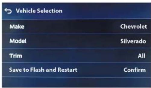
text_image
Vehicle Selection Make Chevrolet Model Silverado Trim All Save to Flash and Restart ConfirmCar Features
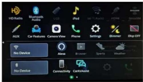
The source for accessing all vehicle information and options.

text_image
Car Features HD Radio Bluetooth Audio iPod Browser AUX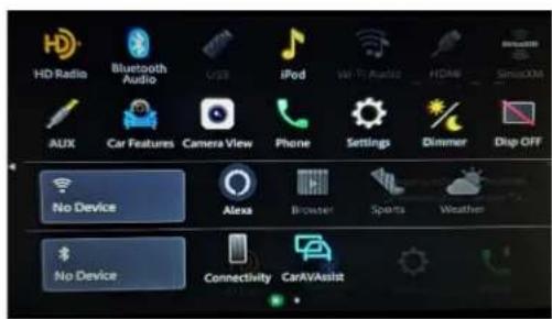
text_image
HD Radio Bluetooth Audio USB iPod WiFi Audio HDMI Sensors AUX Car Features Camera View Phone Settings Dimmer Drop OFF No Device Alexa Browser Sports Weather No Device Connectivity CarAVAssistRADIO OPERATIONS (CONT.)
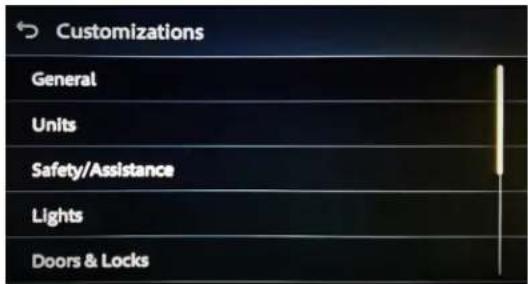
Customizations Menu : Allows full control of vehicle personalization options.
Access this menu by selecting Settings (gear icon) on the previous screenshot:
- Provides Steering Wheel Control (SWC) Configuration.
- Dual Assignment: Assign (2) functions to a single SWC button.
• Remap: Reassign a button on the SWC.
text_image
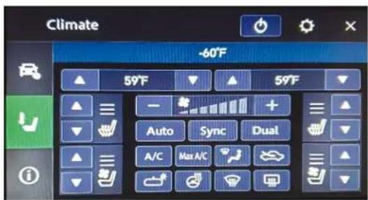
Customizations General Units Safety/Assistance Lights Doors & LocksClimate Screen: HVAC Status only
text_image
Climate -60°F 59°F 59°F Auto Sync Dual A/C Max A/CVehicle Information Screen : The source for accessing all vehicle information and options.
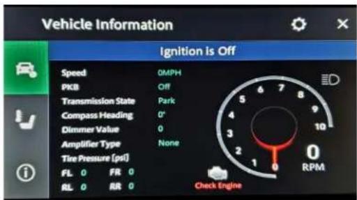
text_image
Vehicle Information Ignition is Off Speed DMPH PKB Off Transmission State Park Compass Heading 0° Dimmer Value 0 Amplifier Type None Tire Pressure (psi) FL 0 FIR 0 RL 0 RR 0 Check EngineRadio ID Screen: Feedback screen for interface software information. - Helpful information for troubleshooting.

text_image
Metra Information Interface HW Version: D Interface FW Version: B.56
AXPIO-SIL1 INSTALLATION INSTRUCTIONS

Having difficulties? We're here to help.
Contact our Tech Support line at:
386-257-1187
Or via email at:
techsupport@metra-autosound.com
Tech Support Hours (Eastern Standard Time)
Monday - Friday: 9:00 AM - 7:00 PM
Saturday: 10:00 AM - 5:00 PM
Sunday: 10:00 AM - 4:00 PM

Metra recommends MECP certified technicians
natural_image
Interior view of a car air conditioner unit with control panel and display screen (no visible text or symbols)natural_image
Diagram of a car interior showing dashboard and steering wheel (no text or labels)(Figura A)
natural_image
Interior view of a car dashboard and infotainment system (no text or symbols visible)(Figura B)
DESMONTAJE DEL TABLERO (CONT.)
natural_image
Interior view of a vehicle showing internal components and structural layout (no text or symbols)(Figura C)

text_image
Tuner box Onstar module(Figura D)
Si usa el LD-LAN09-PIO:
natural_image
Technical line drawing of a mechanical component with no visible text or symbols(Figura E)

text_image
Technical diagram of a mechanical component with numbered parts and red annotation lines(Figura F)
PREPARACIÓN DEL KIT
natural_image
Technical line drawing of a mechanical assembly with no visible text or symbols(Figura A)

natural_image
Technical line drawing of a mechanical housing or enclosure with internal components (no text or symbols)(Figura B)
CONEXIONES

text_image
LD-AX-SPK (N/A) N/A EXTERNAL SPEAKER EXT SPRR CAN 2 CAN3 "TRA" WIRES 40-6PS-P10 GPS 4-PIN MIC HDMI MICRO-HDMI ADAPTER NEEDED AXUSB-GM6 INT 40-6PS-P10 LOCATED AT STEERING COLUMN *IF USING LD-LAN09-P10 CONNECT LOOSE ENDED GREEN/BLACK CONNECT TO CLIMATE PANEL AXXESS INTERFACE 10P 10P CONNECT TO PLUG REMOVED FROM CLIMATE PANEL Pioneer Harness LD-GMLAN09-P10 High-Level PRO4-PIORCA Low-Level 18P (M) 18P (F) (105 or 106) LOCATED AT HMI LD-BACKCAM-MOST CAMERA (10B) AUX (INCL. W/RADIO) USB/AUX (USE INSTEAD) CARSIDE CONNECTD RS (CON JCT DEXTE NSION) (CON I ECTTD PIO/HARNESS) 6-NO-6HX-4X Extension Harness (C CONNECT TO VEHICLE ) Importante: Verifique la instalación de la cámara de reversa, el estado y el control del HVAC, los controles de audio del volante y la salida del altavoz externo antes de completar el ensamblaje del tablero.CONEXIONES (CONT.)
text_image
LD-AX-SPK N/A N/A EXT SPKR CAN2 CAN3 "TRA" WIRE 40-GPS-PIO GPS 4-PIN MIC HDMI ANT MICRO-HDMI ADAPTER NEEDED AXUSB-GM6 AD-EU5 CArsIDE CONNECTORS (CONNECT TO EXTENSION) PRO4-PIORCA LOW-Level High-level PRO4-AVIL-PIO 18P (M) 18P (F) (105 or 106) LOCATED AT HMI CAMERA (10B) AUX (INCL. W/RADIO) USB/AUX (USE INSTEAD) (CONNECT TO PIO HARNESS) LD-BACKAM-MOST Pioneer Harness LD-GMLANTO-PIO AXXESS INTERFACE 16P ZIP CONNECT TO CLIMATE PANEL 10P CONNECT TO PLUG REMOVED FROM CLIMATE PANEL 10P PIONEER HARNESS 16P ZIP LM-DASMANTO-PIO LM-DASMANTO-PIO LM-DASMANTO-PIO LM-DASMANTO-PIO LM-DASMANTO-PIO LM-DASMANTO-PIO LM-DASMANTO-PIO LM-DASMANTO-PIO LM-DASMANTO-PIO LM-DASMANTO-PIO LM-DASMANTO-PIO LM-DASMANTO-PIO LM-DASMANTO-PIO LM-Dasmantopass LM-Dasmantopass LM-Dasmantopass LM-Dasmantopass LM-Dasmantopass LM-Dasmantopass LM-Dasmantopass LM-Dasmantopass LM-Dasmantopass LM-Dasmantopass LM-Dasmantopass LM-Dasmantopass LM-Dasmantopass LM-Dasmantopass LM-Dasmantopass LAD-BACKAM-MOST LM-DASMANTO-PIO LM-DASMANTO-PIO LM-DASMANTO-PIO LM-DASMANTO-PIO LM-DASMANTO-PIO LM-DASMANTO-PIO LM-DASMANTO-PIO LM-DASMANTO-PIO LM-DASMANTO-PIO LM-DASMANTO-PIO LM-DASMANTO-PIO LM-DASMANTO-PIO LM-DASIMARIA DE REVERGADO DE LA Cámara DE REVERGADO DE LA CÁMARA DE REVERGADO DE LA CÁMARA DE REVERGADO DE LA CÁMARA DE REVERGADO DE LA CÁMARA DE REVERGADO DE LA CÁMARA DE REVERGADO DE LA CÁMARA DE REVERGADO DE LA CÁMARA DE REVERGADO DE LA CÁMARA DE REVERGADO DE LA CÁMARA DE REVERGADO DE LA CÁMARA DEL HVAC, LOS CONTROLS DE AUDIO DEL VOLANTE Y LA SALIDA DEL ALTAVOZ EXTERNO ANTES DE COMPLETAR EL ENSMABLAJE DEL TABLERO. LM-DASMANTO-PIO LM-DASMANTO-PIO LM-DASMANTO-PIO LM-DASMANTO-PIO LM-DASMANTO-PIO LM-DASMANTO-PIO LM-DASMANTO-PIO LM-DASMANTO-PIO LM-DASMANTO-PIO LM-DASMANTO-PIO LM-DASMANTO-PIO LM-DASMANTO-PIO LM-DASMINTOPR04-AVIL-PIO LM-DASMINTOPR04-AVIL-PIO LM-DASMINTOPR04-AVIL-PIO LM-DASMINTOPR04-AVIL-PIO LM-DASMINTOPR04-AVIL-PIO LM-DASMINTOPR04-AVIL-PIO LM-DASMINTOPR04-AVIL-PIO LM-DASMINTOPR04-AVIL-IOLOCCAOILOCCAOILOCCAOILOCCAOILOCCAOILOCCAOILOCCAOILOCCAOILOCCAOILOCCAOILOCCAOILOCCAOILOCCAOILOCCAOILOCCAOILOCCAOILOCCAOILOCCAOILOCCAOILOCCAOILOCCAOILOCCAOILOCCAOILOCCAOILOCCAOILOCCAO ILOCCAOILOCCAOILOCCAOILOCCAOILOCCAOILOCCAOILOCCAOILOCCAOILOCCAOILOCCAOILOCCAOILOCCAOILOCCAOILOCCAOILOCCAOILOCCAOILOCCAOILOCCAOILOCCAOILOCCAOILOCCAOILOCCAOILOCCAOILOCCAOILOCCAOENSAMBLE DEL KIT
natural_image
Technical line drawing of a car dashboard frame with no visible text or symbols
natural_image
Technical line drawing of a car dashboard with control panel and buttons (no text or symbols)
natural_image
Technical line drawing of a vehicle dashboard and two connected electrical components (no text or symbols)(Figura C)(Figura A) (Figura B)
text_image
Vehicle Selection Make No Selection Model Trim Save to Flash and Restart Confirm
text_image
Vehicle Selection Make Chevrolet Model Silverado Trim All Save to Flash and Restart Confirm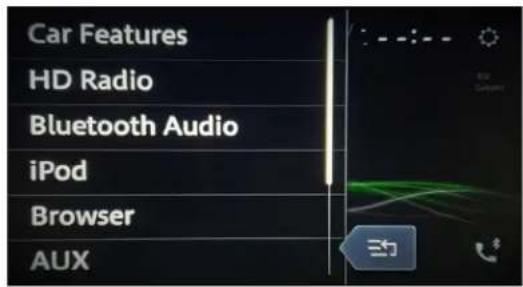
text_image
Car Features HD Radio Bluetooth Audio iPod Browser AUX