99-7523S - Kit d'installation auto AXESS - Free user manual and instructions
Find the device manual for free 99-7523S AXESS in PDF.

User questions about 99-7523S AXESS
0 question about this device. Answer the ones you know or ask your own.
Ask a new question about this device
Download the instructions for your Kit d'installation auto in PDF format for free! Find your manual 99-7523S - AXESS and take your electronic device back in hand. On this page are published all the documents necessary for the use of your device. 99-7523S by AXESS.
USER MANUAL 99-7523S AXESS
INSTALLATION INSTRUCTIONS FOR PART 99-7523S
APPLICATIONS
Mazda 6 2003-2005 99-75235
KIT FEATURES
• Double DIN radio provision
• ISO DIN radio provision with pocket
- Painted silver
- Pre-wired ASWC-1 harness included (ASWC-1 sold separately)
natural_image
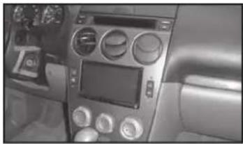
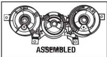
Interior view of a car dashboard with air conditioners and controls (no visible text or symbols)KIT COMPONENTS
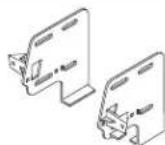
• A) Radio/Climate control housing • B) Radio brackets • C) Pocket • D) (4) #8 x 3/8" Phillips screws
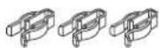
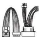
• E) (6) Plastic panel clips • F) Harness • G) (2) #8 x 1" Phillips screws
A

B
E
C


D

F
G

WIRING & ANTENNA CONNECTIONS (sold separately)
Wiring Harness: • Included with kit Antenna Adapter: • Not required
Table of Contents
Dash Disassembly
- Mazda 6 2003-2005 ....2-4
Kit Assembly
- Electronic climate control .... 5
- Manual climate control 6
- Felt tape application....7
- ISO DIN radio provision with pocket....8
- Double DIN radio provision 8
- Display customization 9
- Final wiring and assembly 10-11
TOOLS REQUIRED
- Small flat blade screwdriver
- Phillips screwdriver
- Socket wrench
CAUTION: Metra recommends disconnecting the negative battery terminal before beginning any installation. All accessories, switches, and especially air bag indicator lights must be plugged in before reconnecting the battery or cycling the ignition.
NOTE: Refer to the instructions included with the aftermarket radio.

99-75235
Dash Disassembly
Electronic Climate Control
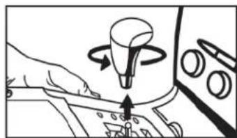
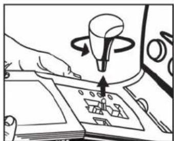
- Unscrew the shift knob counter clockwise to remove. (Figure A)
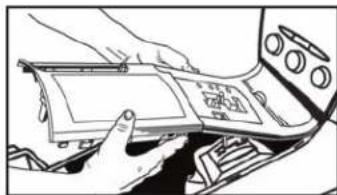
- Unclip and remove the cup holder/parking brake cover and shifter cover as one radio. (Figure B)
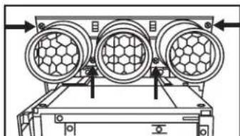
- Remove (2) Phillips screws from the bottom of the radio/climate control panel. (Figure C)
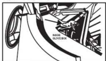
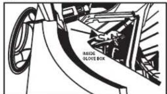
- Open glove box, squeeze sides together and let open fully then remove (1) 10 mm bolt from the side of the radio bracket. (Figure D)
natural_image
Illustration of a hand pressing a button on a control panel with a rotating knob (no text or symbols)
natural_image
Person interacting with a device inside a vehicle or control panel (no visible text or symbols)(Figure B) (Figure F)
natural_image
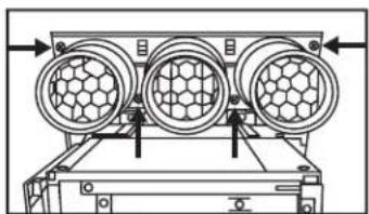
Diagram of a device rear panel with three circular components and mounting brackets (no text or symbols)(Figure C) (Figure G)
text_image
IRSIDE GLOVE BOX(Figure D) (Figure H)(Figure A)
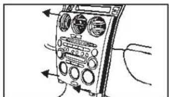
- Unsnap and remove radio/climate control panel including climate control vents at the top. (Figure D)
- Remove (4) Phillips screws securing vents to radio/climate control panel to remove. (Figure E)
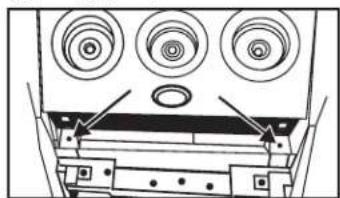
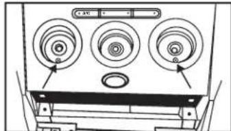
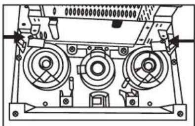
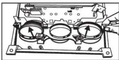
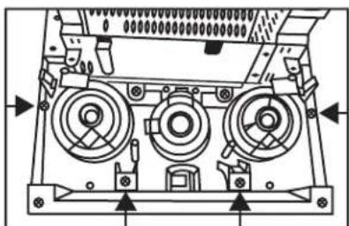
- Remove (8) Phillips screws securing the electronic climate control to the radio/climate control panel to remove. (Figure F)
- Remove (4) Phillips screws securing the radio display harness bracket to the radio chassis then unclip and remove the radio display harness. (Figure H) Continue to kit assembly
natural_image
Diagram of an analog multimeter with control panel and wiring (no text or labels)(Figure E)

natural_image
Technical diagram of a mechanical device with three circular components and directional arrows indicating flow or movement (no text or symbols)
text_image
Rear of Radio/Climate Control Panel Rear of Electronic Climate Control
natural_image
Technical line drawing of a mechanical device with no visible text or symbols
99-75235
Dash Disassembly
Manual Climate Control
- Unscrew the shift knob counter clockwise to remove. (Figure A)
- Unclip and remove the cup holder/parking brake cover and shifter cover as one radio. (Figure B)
- Remove (2) Phillips screws from the bottom of the radio/climate control panel. (Figure C)
- Pull the climate control knobs off and remove (2) Phillips screws from behind knobs. (Figure D)
natural_image
Illustration of a hand using a device to interact with a mechanical component (no text or symbols visible)(Figure A)
natural_image
Illustration of hands installing or adjusting a device panel on a vehicle (no text or symbols visible)(Figure B)

natural_image
Technical diagram of a device rear panel with three circular components and mounting brackets (no text or symbols)(Figure C)
natural_image
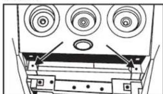
Diagram of a front panel with three circular components and arrows pointing to the top panel (no text or symbols present)(Figure D)
- Open glove box, squeeze sides together and let open fully then remove (1) 10 mm bolt from the side of the radio bracket. (Figure E)
- Unsnap and remove radio/climate control panel including climate control vents at the top. (Figure F)
- Remove (4) Phillips screws securing vents to radio/climate control panel to remove. (Figure G) Continue on next page

text_image
INSIDE GLOVE BOX(Figure E)

text_image
Diagram of a handheld device with labeled control knobs and directional arrows indicating signal flow or measurement.(Figure F)

natural_image
Technical diagram of a mechanical device with three circular components and directional arrows indicating movement (no text or symbols)(Figure G)

99-75235
Dash Disassembly
Manual Climate Control (continued)
- Remove the (2) small Phillips screws securing the light bulb boards on each side of the backlight dispersion bar.
Note: Notice how they are positioned in the backlight dispersion bar as they will be placed in the 99-7523S the same way. (Figure H)
- Remove (4) Phillips screws securing backlight dispersion bar and knob trim bezels. (Figure I)
natural_image
Technical line drawing of a mechanical device with three circular components and mounting brackets (no text or symbols)(Figure H) (Figure J)

natural_image
Technical diagram of a mechanical device with three circular components and directional arrows indicating assembly or movement (no text or symbols present)(Figure I) (Figure K)
- Push the bottom edges of the knob trim bezels from the front side to the back and slide both pieces out as one radio. (Figure J)
- Remove (4) Phillips screws securing the radio display harness bracket to the radio chassis then unclip and remove the radio display harness. (Figure K)
Continue to kit assembly

natural_image
Technical line drawing of a mechanical device with three circular components and mounting holes (no text or symbols)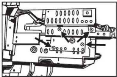
natural_image
Technical diagram of an electronic device with labeled components and wiring (no readable text or symbols)
99-75235
Kit Assembly
Electronic Climate Control
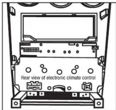
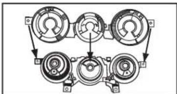
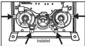
- Clip the climate control knob outer trim ring panel into the 99-7523S housing. (Figure A)
- Align the screw holes in the climate control and the radio housing panel then push the climate control onto the radio housing panel. (Figure B)
natural_image
Technical diagram of a mechanical assembly with three circular components and directional arrows indicating motion (no text or symbols)(Figure A)
text_image
Rear view of electronic climate control(Figure B)
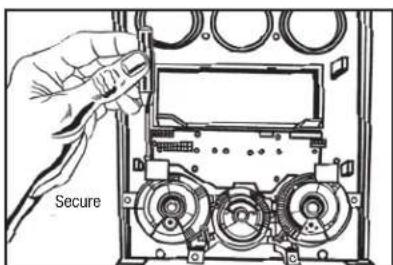
- Secure the climate control with the factory hardware removed in step 7 of the dash disassembly for electronic climate control cars.
- Unclip and remove the small oval cover plate at the bottom center of the factory radio and insert into the 99-7523S radio housing. (Figure C)
Note: The light bulb boards will not be used with auto climate control vehicles disregard these bulbs.

natural_image
Diagram of a vehicle dashboard with circular components and directional arrows indicating movement (no text or symbols)(Figure C)

99-75235
Kit Assembly
Manual Climate Control:
- Put the climate control knob outer trim panel and the backlight dispersion bar together and clip into the radio housing panel as one radio.
Note: You may have to push down slightly on the middle of the radio to ease in positioning it into the kit. (Figures A, B, C)
- Secure the radio with the factory hardware removed in step 9 of the manual climate control dash disassembly.
flowchart
graph TD
    A["Component 1"] --> B["Component 2"]
    B --> C["Component 3"]
    C --> D["Component 4"]
    D --> E["Component 5"]
    E --> F["Component 6"]
    F --> G["Component 7"]
    G --> H["Component 8"]
    H --> I["Component 9"]
    I --> J["Component 10"]
    J --> K["Component 11"]
    K --> L["Component 12"]
    L --> M["Component 13"]
    M --> N["Component 14"]
    N --> O["Component 15"]
    O --> P["Component 16"]
    P --> Q["Component 17"]
    Q --> R["Component 18"]
    R --> S["Component 19"]
    S --> T["Component 20"]
(Figure A)
natural_image
Technical line drawing of a three-c� mechanical assembly with no visible text or symbols(Figure B)

text_image
Installed(Figure C)
-
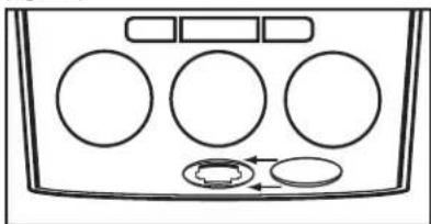
Secure the light bulb boards on each side of the backlight dispersion bar using the factory hardware removed in step 8 in manual climate control dash disassembly. (Figure D)
-
Unclip and remove the small oval cover plate at the bottom center of the factory radio and insert into the 99-7523S radio housing. (Figure E)
text_image
Secure(Figure D)
natural_image
Diagram of a vehicle dashboard with circular components and directional arrows indicating movement (no text or symbols)(Figure E)

99-75235
Kit Assembly
Felt Tape Application
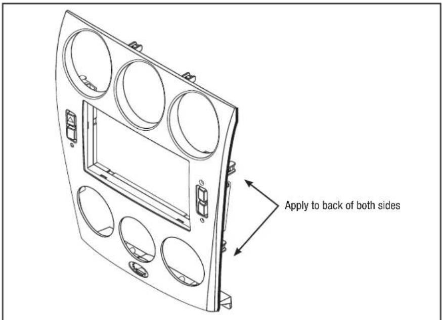
Note: Due to differences in factory tolerances you may need to apply the provided felt tape to the edge of the 99-7523S radio housing to relieve backlight bleed through.
- Looking at edge of radio housing apply felt tape to inner edge (toward back of kit). If it is positioned to closely to the outer edge you may be able to see it once it is in the dash. (Figure A)
- Attach the included six panel clips to the radio housing.
text_image
Apply to back of both sides(Figure A)

99-75235
Kit Assembly
ISO DIN radio provision with pocket
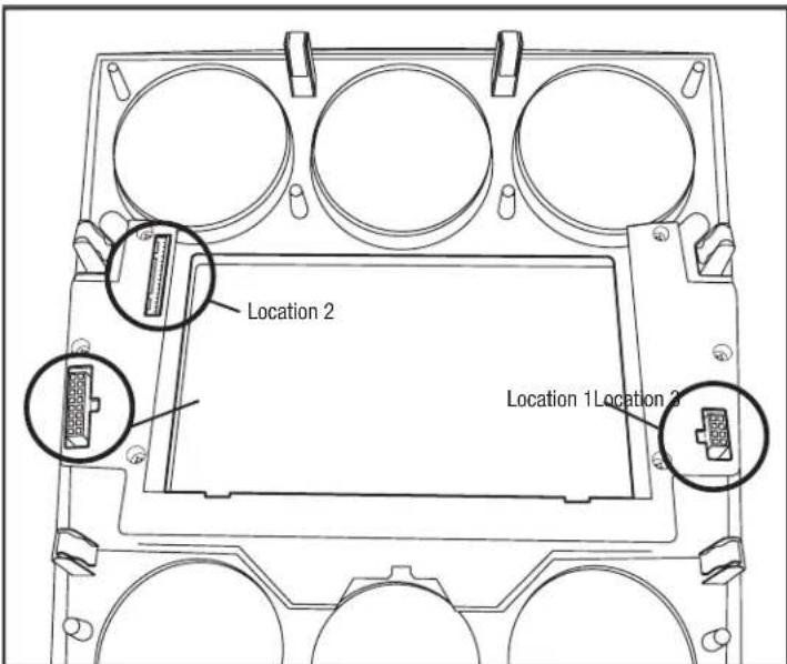
- Mount the pocket to the radio brackets with the (4) #8 x 3/8" Phillips screws supplied. (Figure A)
- Slide the radio into the radio brackets/pocket assembly and secure with the screws supplied with the radio. (Figure B)
- Locate the factory wiring harness and antenna plug in the dash.
- Mount the new radio assembly into the dash and reassemble dash in reverse order of disassembly.
- There are no existing holes for the radio mounting. New holes will be made using the included one inch screws. The radio brackets will rest on a shelf in the sub-dash. Be sure the radio is level and centered while mounting the radio/ bracket assembly into the dash opening.
Continue on next page

natural_image
Technical line drawing of a mechanical assembly with mounting brackets and a central housing (no text or symbols)(Figure A)

natural_image
Technical line drawing of a mechanical device with labeled components (no text or symbols present)(Figure B)
Double DIN radio provision
- Attach the double DIN radio to the radio brackets using the screws supplied with the radio. (Figure A)
- Locate the factory wiring harness and antenna plug in the dash.
- Mount the new radio assembly into the dash and reassemble dash in reverse order of disassembly.
- There are no existing holes for the radio mounting. New holes will be made using the included one inch screws. The radio brackets will rest on a shelf in the sub-dash. Be sure the radio is level and centered while mounting the radio/ bracket assembly into the dash opening.
Continue on next page

natural_image
Technical line drawing of a device housing with internal components and mounting holes (no text or symbols)(Figure A)

99-75235
Kit Assembly
Start the car and test all the climate control functions.
Note: The air recirculation light will be on at initial startup and will not go out until using the climate controls for the first time.
Display Customization:
-
Press and hold the Clock button in the factory display until "Set Text" is displayed then release button. Settings will begin with the first character location. Use the Set button to select the desired character then press the AMB button to select the next character location. There are 10 available character locations.
-
Once the desired text is entered if you do not touch any buttons for 10-seconds the display will read "Saved Text" and your text will be saved.
-
To set the clock press and hold the Clock button until "Hr. Adjust" is displayed then use the Set button to select the desired hour.
-
Press the Clock button again and the display will read "Min. Adjust" then use the Set button to select the desired minutes.
Note: If equipped with a dimmer button it will still function as normal.
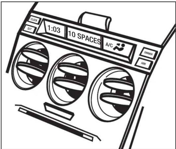
text_image
CLOCK SET 1:03 10 SPACES A/C DIMMER AMSMetra
99-75235
Final Wiring and Assembly
Connections to be made to the aftermarket radio:
- Connect the Yellow wire to the 12-volt battery/memory wire.
- Connect the Red wire tot he accessory/ignition wire.
- Connect the Orange wire to the illumination wire. If the aftermarket radio has no illumination wire, cap off the Orange wire.
- Cap off and disregard the Orange/White wire, it will not be used in this application.
- Connect the Black wire tot he ground wire.
- Connect the Blue wire to the antenna turn on wire.
- Connect the Blue/White wire to the amp turn-on wire, if the vehicle also amplified.
- Connect the White wire to the left front positive speaker output.
- Connect the White/Black wire to the left front negative speaker output.
- Connect the Gray wire to the right front positive speaker output.
- Connect the Gray/Black wire to the right front negative speaker output.
-
Connect the Green wire to the radio's left rear positive speaker output.
-
Connect the Green/Black wire tot he radio's left rear negative speaker output.
- Connect the Purple wire to the radio's right rear positive speaker output.
- Connect the Purple/Black wire tot he radio's right rear negative speaker output.
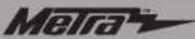
Connections to be made to the kit:
- Plug the 8-way connector supplied with the 99-7523 into Location 1, on the back of the 99-7523 radio housing (see diagram, on right).
- Plug the 16-way connector, that was removed from the factory radio, into Location 2 (see diagram, on right).
- For manual climate control vehicles only: Plug the 16-way connector supplied with the 99-7523 into Location 3 (see diagram, on right).
Nota: Automatic climate control vehicles will not use this harness.
- Reconnect the negative battery terminal and test the radio for proper operation.
- Reassemble the radio and dash assemblies in reverse order of disassembly.
99-75235
Notes
text_image
Location 2 Location 1 Location 2(99-7523 radio housing diagram)

INSTALLATION INSTRUCTIONS FOR PART 99-7523S


KNOWLEDGE IS POWER
Enhance your installation and fabrication skills by enselling in the most recognized and presented.
enrolling in the most recognized and resp. mobile electronics school in our industry.
Log onto www.installerinstitute.com or call
800-354-6782 for more information and take steps toward a better tomorrow.

Metra recommends MECP
certified technicians

natural_image
Interior view of a car dashboard with air conditioners and a digital display (no visible text or symbols)COMPONENTES DEL KIT
natural_image
Line drawing of a hand pressing a button on a control panel with a light bulb (no text or symbols)
natural_image
Person interacting with a device inside a vehicle or control panel (no visible text or symbols)(Figura B) (Figura F)

natural_image
Diagram of a device rear panel with three circular components and mounting brackets (no text or symbols)(Figura C) (Figura G)
text_image
IMBIDE GLOVE BOX(Figura D) (Figura H)(Figura A)
text_image
Diagram of an analog multimeter with labeled ports and connections, showing dials, knobs, and a display panel.(Figura E)
natural_image
Technical diagram of a mechanical device with three circular components and directional arrows indicating flow or movement (no text or symbols present)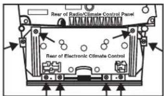
text_image
Rear of Radio/Climate Control Panel Rear of Electronic Climate Control
natural_image
Technical line drawing of a mechanical device with no visible text or symbols
99-75235
natural_image
Illustration of a hand using a device to interact with a mechanical component (no text or symbols visible)(Figura A)

natural_image
Illustration of hands installing or adjusting a device component (no text or symbols visible)(Figura B)
natural_image
Technical diagram of a mechanical or electronic component with three circular features and directional arrows indicating assembly or movement (no text or symbols present)(Figura C)

natural_image
Diagram of a front panel with three circular components and labeled arrows pointing to them (no text or symbols present)(Figura D)
natural_image
Diagram of a handheld electronic device with multiple ports and cables (no visible text or labels)(Figura F)
natural_image
Technical diagram of a mechanical device with three circular components and directional arrows indicating motion (no text or symbols)(Figura G)

99-75235
natural_image
Technical line drawing of a mechanical device with three circular components and mounting brackets (no text or symbols)(Figura H) (Figura J)
natural_image
Technical diagram of a mechanical device with three circular components and directional arrows indicating assembly or movement (no text or symbols present)(Figura I) (Figura K)
natural_image
Technical line drawing of an electronic device with three circular components and a handle (no text or symbols)
text_image
Technical diagram of an electronic device with labeled components and directional arrows indicating movement or assembly.
99-75235
Ensamble del kit
natural_image
Technical diagram of a mechanical assembly with three circular components and directional arrows indicating motion (no text or symbols)(Figura A)

text_image
Rear view of electronic climate control(Figura B)
natural_image
Diagram of a vehicle dashboard with circular components and directional arrows indicating movement (no text or symbols)(Figura C)

99-75235
Ensamble del kit
Control manual de clima:
natural_image
Technical line drawing of a three-c� mechanical assembly with no visible text or symbols(Figura B)
text_image
Installed(Figura C)
natural_image
Diagram of a vehicle dashboard with circular components and directional arrows indicating movement (no text or symbols)(Figura E)

99-75235
Ensamble del kit
natural_image
Technical line drawing of a mechanical assembly with mounting brackets and a central component (no text or symbols)(Figura A)

natural_image
Technical line drawing of a mechanical device with internal components and mounting holes (no text or symbols)(Figura B)
Doule DIN radio provision
natural_image
Technical line drawing of an electronic device casing with internal components and mounting holes (no text or symbols)(Figura A)
99-75235