99-5831G - Kit d'installation auto AXESS - Free user manual and instructions
Find the device manual for free 99-5831G AXESS in PDF.

User questions about 99-5831G AXESS
0 question about this device. Answer the ones you know or ask your own.
Ask a new question about this device
Download the instructions for your Kit d'installation auto in PDF format for free! Find your manual 99-5831G - AXESS and take your electronic device back in hand. On this page are published all the documents necessary for the use of your device. 99-5831G by AXESS.
USER MANUAL 99-5831G AXESS
natural_image
Interior view of a car dashboard with air conditioner and touchscreen (no visible text or symbols)Ford Transit Connect (with factory 4.2" display) 2014-2018
Visit MetraOnline.com for more detailed information about the product and up-to-date vehicle specific applications
KIT FEATURES
• ISO DIN radio provision with pocket
- ISO DDIN radio provision
- Passenger airbag indicator
- Painted black (99-5831B), or charcoal gray with black (99-5831G)
KIT COMPONENTS
• A) Radio trim panel • B) Radio brackets • C) Pocket • D) (4) Panel clips • E) (4) #8 x 3/8" Phillips screws
AB
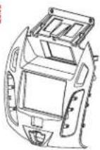
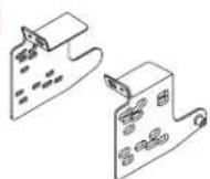


TABLE OF CONTENTS
Dash Disassembly 2
Kit Assembly
-ISO DIN radio provision with pocket ....3
-ISO DDIN radio provision ....3
WIRING & ANTENNA CONNECTIONS (sold separately)
Wiring Harness: XSVI-5524-NAV or AX-ADBOX2 & AX-ADFD02
Antenna Adapter: 40-EU10
TOOLS REQUIRED
- Panel removal tool • Phillips screwdriver
• T-15 Torx driver • T-20 Torx driver
Attention! Let the vehicle sit with the key out of the ignition for a few minutes before removing the factory radio. When testing the aftermarket equipment, ensure that all factory equipment is connected before cycling the key to ignition.
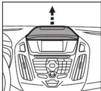
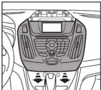
DASH DISASSEMBLY
- Remove the top panel above the display. (Figure A)
- Remove (2) T-15 Torx screws above the display/radio panel. (Figure B)
- Unplug and remove the display/radio panel. (Figure C)
natural_image
Front view of a car dashboard with no visible text or symbols(Figure A) (Figure C)
- Remove the A/C vents and hazard switch from the panel and set aside for kit assembly.
- Remove (2) T-20 Torx screws from the top of the radio, and then unplug and remove from the dash cavity. (Figure D)
Continue to Kit Assembly
natural_image
Top-down line drawing of a car dashboard with control panels and directional arrows (no text or symbols)
natural_image
Technical line drawing of a vehicle chassis with internal components and no visible text or symbols
natural_image
Top-down line drawing of a car's front dashboard and rear seats (no text or symbols)(Figure B) (Figure D)
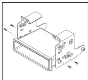
KIT ASSEMBLY
ISO DIN radio provision with pocket
- Secure the pocket to the radio brackets using the (4) #8 x 3/8" Phillips screws supplied. (Figure A)
- Remove the metal "DIN" sleeve and trim ring from the aftermarket radio.
- Slide the radio into the bracket/pocket assembly, then secure the radio using the screws supplied with the radio. (Figure B)
- Snap the hazard switch into the radio trim panel from the front.
- Snap the A/C vents into the radio trim panel from the back.
- Plug in the passenger airbag light and hazard connections.
- Locate the factory wiring harness and antenna connector in the dash, and complete all necessary connections to the radio. Metra recommends using the proper mating adapter from Metra and/or AXXESS
- Attach (4) panel clips to the radio trim panel, then reassemble the dash in reverse order of disassembly, using the 99-5831 radio trim panel.
natural_image
Technical line drawing of a mechanical housing or enclosure with mounting brackets and internal components (no text or symbols)(Figure A) (Figure A)

natural_image
Technical line drawing of an electronic device with ports and connectors (no text or symbols)(Figure B)
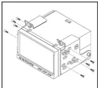
ISO DDIN radio provision
- Secure the radio brackets to the radio using the screws supplied with the radio. (Figure A)
- Snap the hazard switch into the radio trim panel from the front.
- Snap the A/C vents into the radio trim panel from the back.
- Plug in the passenger airbag light and hazard connections.
- Locate the factory wiring harness and antenna connector in the dash, and complete all necessary connections to the radio. Metra recommends using the proper mating adapter from Metra and/or AXXESS.
- Attach (4) panel clips to the radio trim panel, then reassemble the dash in reverse order of disassembly, using the 99-5831 radio trim panel.
natural_image
Technical line drawing of an electronic device casing with ports and connectors (no text or symbols)If you are having difficulties with the installation of this product, contact our Tech Support line either by phone at 1-800-253-TECH, or email at techsupport@metra-autosound.com. Before doing so, look over the instruction booklet a second time and ensure that the installation was performed exactly as the instruction booklet is stated. Have the vehicle apart and ready to perform troubleshooting steps before contacting Metra/Axxess Tech Support.

KNOWLEDGE IS POWER
Enhance your installation and fabrication skills by enrolling in the most recognized and respected mobile electronics school in our industry. Log onto www.installerinstitute.com or call 800-354-6782 for more information and take steps toward a better tomorrow.

Metra recommends MECP certified technicians

natural_image
Interior view of a car dashboard with air conditioner and touchscreen (no visible text or symbols)natural_image
Top-down line drawing of a car's front dashboard and rearview (no text or symbols)(Figura A) (Figura C)
natural_image
Top-down line drawing of a car dashboard with control panels and directional arrows (no text or symbols)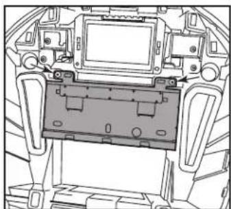
natural_image
Technical line drawing of a vehicle chassis with internal components and no visible text or symbols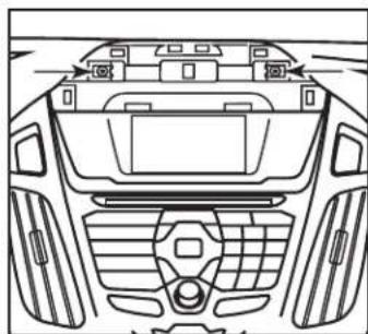
natural_image
Top-down line drawing of a car's front dashboard and rear seats (no text or symbols)(Figura B) (Figura D)
ENSAMBLE DEL KIT
natural_image
Technical line drawing of a mechanical housing assembly with mounting brackets and mounting holes (no text or symbols)(Figura A) (Figura A)

natural_image
Technical line drawing of a mechanical device with ports and mounting brackets (no text or symbols)(Figura B)