99-5827B - Kit d'installation auto AXESS - Free user manual and instructions
Find the device manual for free 99-5827B AXESS in PDF.

User questions about 99-5827B AXESS
0 question about this device. Answer the ones you know or ask your own.
Ask a new question about this device
Download the instructions for your Kit d'installation auto in PDF format for free! Find your manual 99-5827B - AXESS and take your electronic device back in hand. On this page are published all the documents necessary for the use of your device. 99-5827B by AXESS.
USER MANUAL 99-5827B AXESS
natural_image
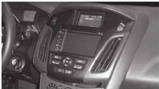
Interior view of a car dashboard with air conditioners and controls (no visible text or symbols)Ford Focus (without MyFord Touch) 2012-2014
KIT FEATURES
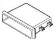
• ISO DIN radio provision with pocket
• ISO DDIN radio provision
• Integrated controls for info center
- Painted matte black (different color vent trim panels available, sold separately)
KIT COMPONENTS
• A) Radio trim panel • B) Radio brackets • C) • Pocket • D) (2) Carriage bolts • E) (2) Keps nuts • F) (4) #8 x 3/8" Phillips screws
AE

natural_image
Line drawing of a car interior frame (no text or symbols)


TABLE OF CONTENTS
Dash Disassembly 2
Kit Preparation 3
Kit Assembly
-ISO DIN radio provision with pocket ....4
-ISO DDIN radio provision ....5
ASWC-1 programming 6
WIRING & ANTENNA CONNECTIONS (sold separately)
Wiring Harness: XSVI-5524-NAV • AX-ADBOX along with AX-ADFD02
Antenna Adapter: 40-EU10
TOOLS REQUIRED
- Panel removal tool • Phillips screwdriver
- Socket wrench • T-25 Torx driver
CAUTION! All accessories, switches, climate controls panels, and especially air bag indicator lights must be connected before cycling the ignition. Also, do not remove the factory radio with the key in the on position, or while the vehicle is running.
DASH DISASSEMBLY
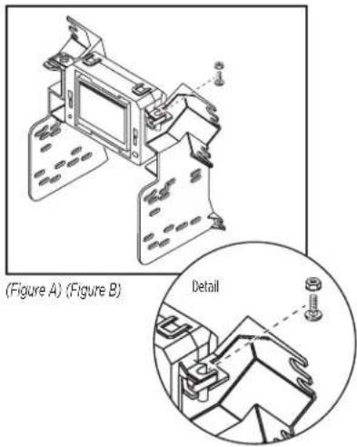
- Remove the screw cover facing up on the bottom of the radio control panel. (Figure A)
- Remove (2) T-25 Torx screws from under the cover. (Figure B)

natural_image
Line drawing of a car interior showing structural components and a person adjusting parts (no text or symbols)(Figure A) (Figure C)
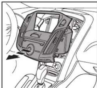
- Unclip and remove the entire radio control panel including the A/C vents. (Figure C)
- Remove (4) T-25 Torx screws securing the radio and (4) T-25 Torx screws securing the factory display and bracket. (Figure D)
Continue to Kit Preparation
natural_image
Interior view of a car showing the dashboard and steering wheel (no text or symbols visible)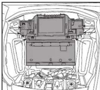
natural_image
Top-down line drawing of a car interior showing internal components like monitors and electronic devices (no text or symbols)(Figure D)

natural_image
Interior view of a car dashboard and infotainment system (no text or symbols visible)(Figure B)
KIT PREPARATION
- Unclip and remove the A/C vents from the factory radio panel. (Figure A)
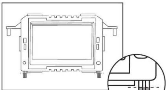
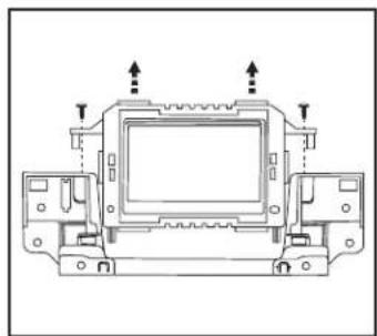
- Remove the factory display from the factory bracket assembly. (Figure B)
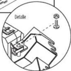
- Cut and remove the (2) tabs on the bottom of the factory display. (Figure C)
- Clip the A/C vents, removed from Step 1, onto the 99-5827B radio trim panel. (Figure D)
Continue to Kit Assembly

natural_image
Technical line drawing of a vehicle chassis with labeled components and directional arrows indicating movement (no text or symbols present)(Figure A)

natural_image
Technical line drawing of a mechanical component with mounting holes and a close-up inset showing internal structure (no text or symbols)(Figure C)

natural_image
Technical line drawing of a mechanical assembly with mounting holes and arrows indicating direction (no text or symbols)(Figure B)

natural_image
Technical line drawing of a car interior showing structural components and a door mechanism (no text or symbols)(Figure D)
KIT ASSEMBLY
ISO DIN radio provision with pocket
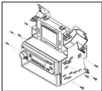
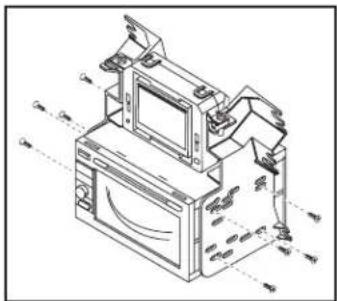
- Mount the factory display to the radio housing brackets with the supplied carriage bolts and Keps nuts. (Figure A)
- Mount the pocket to the radio housing bracket/display assembly with the (4) #8 x 3/8" Phillips screws supplied. (Figure B)
- Remove the metal DIN sleeve and trim ring from the aftermarket radio.
- Slide the radio into the radio bracket assembly and secure with screws supplied with the radio. (Figure B)
- Locate the factory wiring harness and antenna plug in the dash. Metra recommends using the proper mating adapters from Metra and/or AXXESS.

natural_image
Technical line drawing of a mechanical assembly with no visible text or symbols(Figure A) (Figure B)

text_image
Detail- Mount the assembly into the sub dash.
- Reassemble the dash in the reverse order of disassembly using the 99-5827B trim panel instead of the factory panel.
Note: The integrated buttons on this kit are used to navigate the factory display above the radio. The button below the info button can be used to turn the factory screen on and off if desired. The remainder of the control functions are the same as factory was prior to aftermarket installation.
Continue to ASWC-1 programming
natural_image
Technical line drawing of a mechanical device with no visible text or symbolsKIT ASSEMBLY
ISO DDIN radio provision
- Mount the factory display to the radio housing brackets with the supplied carriage bolts and Keps nuts. (Figure A)
- Slide the radio into the radio bracket assembly and secure with screws supplied with the radio. (Figure B)
- Locate the factory wiring harness and antenna plug in the dash. Metra recommends using the proper mating adapters from Metra and/or AXXESS.
- Mount the assembly into the sub dash.
- Reassemble the dash in the reverse order of disassembly using the 99-5827B trim panel instead of the factory panel.
text_image
(Figure A) (Figure B) DetailNote: The integrated buttons on this kit are used to navigate the factory display above the radio. The button below the info button can be used to turn the factory screen on and off if desired. The remainder of the control functions are the same as factory was prior to aftermarket installation.
Continue to ASWC-1 programming
natural_image
Technical line drawing of an electronic device with monitor, keyboard, and display unit (no text or symbols)ASWC PROGRAMMING (SOLD SEPARATELY)
This step is for models with SYNC. For models without SYNC, please refer to axxessinterfaces.com for wiring and programming information.
- With all connections completed, and the factory display reconnected, turn the ignition on.
- On the 99-5827B radio trim panel, press and hold the button with the flat line above the L.E.D. until the time and date show on the factory display. (Figure A)
- Activate SYNC with the button on the steering wheel, and then tell SYNC to go to "Line In". The voice should confirm "Sync Line In", and then show on the display.
- Once set to "Line In", turn the vehicle off, and then start the vehicle. "Line In" will then show on the factory display.
- Connect the 12-pin harness into the ASWC-1 at this time. The ASWC-1 will then flash rapidly.
Note: If the ASWC-1 has been previously installed, press the reset button for 3 seconds, and then release. - Tap "Volume-Up" on the steering wheel until the L.E.D. on the ASWC-1 stops flashing rapidly. The ASWC-1 will pause for a moment, flash several times (about 10 seconds), and then light up solid. At this point the ASWC-1 is programmed.
- For further programming or troubleshooting, please refer to the instructions supplied with the ASWC-1.

text_image
Hold this button until the time and date shows on the factory screen.(Figure A)
IMPORTANT
If you are having difficulties with the installation of this product, please call our Tech Support line at 1-800-253-TECH. Before doing so, look over the instructions a second time, and make sure the installation was performed exactly as the instructions are stated. Please have the vehicle apart and ready to perform troubleshooting steps before calling.

KNOWLEDGE IS POWER
Enhance your installation and fabrication skills by enrolling in the most recognized and respected mobile electronics school in our industry. Log onto www.installerinstitute.com or call 800-354-6782 for more information and take steps toward a better tomorrow.

Metra recommends MECP certified technicians
natural_image
Interior view of a car dashboard with air conditioners and a digital display (no visible text or symbols)Ford Focus (Sin MyFord Touch) 2012-2014
CARACTERÍSTICAS DEL KIT
The image is too blurry to recognize any text content.


INDICE
natural_image
Line drawing of a car interior showing dashboard and engine compartment (no text or symbols)(Figura A) (Figura C)
natural_image
Interior view of a car showing the dashboard and steering wheel (no text or symbols visible)
natural_image
Technical line drawing of a car engine bay with internal components and no visible text or symbols(Figura D)

natural_image
Interior view of a car dashboard and infotainment system (no text or symbols visible)(Figura B)
PREPARACIÓN DEL KIT
natural_image
Technical line drawing of a vehicle chassis with mounting brackets and structural components (no text or symbols)(Figura A)
natural_image
Technical line drawing of a mechanical component with mounting holes and a close-up inset showing internal structure (no text or symbols)(Figura C)
natural_image
Technical line drawing of a mechanical component with mounting holes and arrows indicating assembly or movement (no text or symbols)(Figura B)

natural_image
Technical line drawing of a car interior showing structural components and a door mechanism (no text or symbols)(Figura D)
ENSAMBLE DEL KIT
natural_image
Technical line drawing of a mechanical assembly with no visible text or symbols(Figura A) (Figura B)