99-5716 - Kit d'installation auto AXESS - Free user manual and instructions
Find the device manual for free 99-5716 AXESS in PDF.

User questions about 99-5716 AXESS
0 question about this device. Answer the ones you know or ask your own.
Ask a new question about this device
Download the instructions for your Kit d'installation auto in PDF format for free! Find your manual 99-5716 - AXESS and take your electronic device back in hand. On this page are published all the documents necessary for the use of your device. 99-5716 by AXESS.
USER MANUAL 99-5716 AXESS
• ISO DIN head unit provisions
• Incorporates factory climate controls into installation

natural_image
Close-up of a vintage industrial control panel with multiple dials and a central display (no visible text or symbols)KIT COMPONENTS
• A) Integrated mounting kit • B) ISO Faceplate • C) Tuner bypass • D) ISO Brackets
• E) (2) #8 x 3/8" Phillips pan head screws
A

natural_image
Line drawing of a car dashboard with three buttons and a central display (no text or symbols)B
C

natural_image
Pure electrical connector diagram without any text, numbers, or symbolsD

E

WIRING & ANTENNA CONNECTIONS (included)
WiringHarness:
- Included with dash kit
Antenna Adapter:
- 40-FD10
TOOLS REQUIRED
- 86-5618 Head unt removal keys - Torx head screwdriver


- ISO head unit provision....6
- DIN head unit provision....7
- Trunk provision ....8
CAUTION: Metra recommends disconnecting the negative battery terminal before beginning any installation. All accessories, switches, and especially air bag indicator lights must be plugged in before reconnecting the battery or cycling the ignition.
Note: Refer to the instructions included with the aftermarket radio.

KNOWLEDGE IS POWER
Enhance your installation and fabrication skills by enrolling in the most recognized and respected mobile electronics school in our industry. Log onto www.installerinstitute.com or call 800-354-6782 for more information and take steps toward a better tomorrow.

Metra recommends MECP certified technicians
Ford Taurus/Mercury Sabel 2000-2003
- Using the 86-5618 removal keys pull the factory radio/climate control panel from the dash. (Figure A)
- Disconnect the vacuum hose harness and connectors from the audio system, blower motor switch, A/C dampener door switch, and potentiometer.
- Remove the panel. Continued to kit preparation

natural_image
Line drawing of a device with two ports and a front panel, no text or symbols present(Figure A)
Ford Taurus/Mercury Sabel 2000-2003
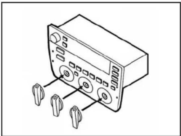
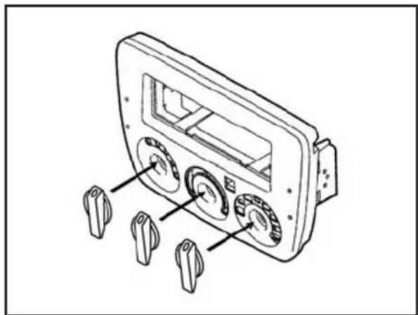
- Turn the factory climate control dials into a vertical position and pull the dials off. (Figure A)
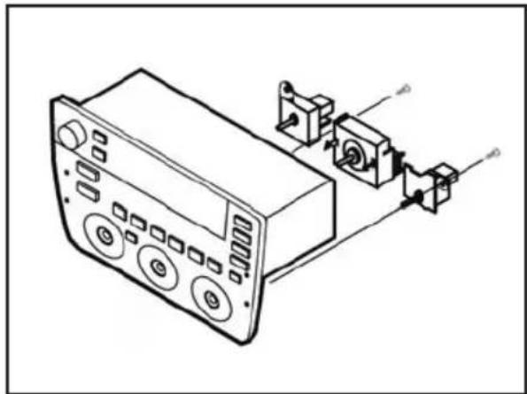
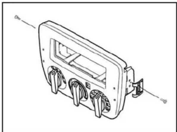
- Remove (2) 5/16" hex head screws securing the temperature/fan control switches and remove switches. Unclip the climate control switch and remove. (Figure B)
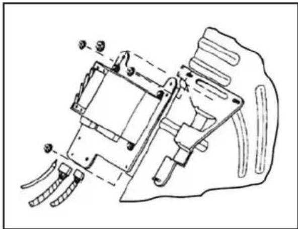
- Mount switches to the back of the integrated mounting kit with the (2) supplied #8 x 3/8" Phillips pan head screws. (Figure C)
- Holding the climate control dials in a vertical position insert the dials onto the posts of the mounted switches and secure. (Figure D)
Continue on next page
natural_image
Line drawing of a device with buttons and ports, no text or symbols present(Figure B)

natural_image
Technical line drawing of a car air conditioner unit with mounting brackets and control panel (no text or labels)(Figure C)
natural_image
Line drawing of a portable electronic device with control buttons and three hanging knobs (no text or symbols)(Figure A)

natural_image
Line drawing of a device control panel with three rotary buttons and four terminal holders (no text or symbols)(Figure D)
Ford Taurus/Mercury Sabel 2000-2003
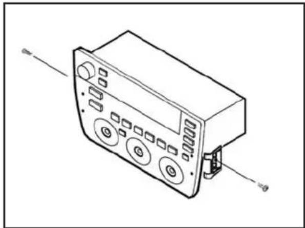
- Remove (2) Torx head screws securing the mounting clips to the sides of the factory radio/climate control panel and remove the clips. (Figure E)
- Mount the clips to the integrated mounting kit with the same Torx head screws. (Figure F)
Continue to kit assembly
natural_image
Line drawing of a device with buttons and a connector (no text or symbols)(Figure E)
natural_image
Line drawing of an electrical enclosure with three leads and a central display (no text or symbols)(Figure F)
ISO head unit provision
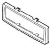
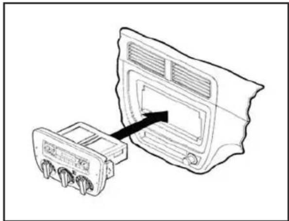
- Snap the ISO Faceplate into the radio opening. (Figure A)
- Attach the ISO Brackets to the inner lip of the radio opening. (Figure A)
- Slide the head unit into the radio opening, align the holes in the head unit with the holes in the ISO Brackets and mount the unit to the brackets with the screws supplied with the unit. (Figure A)
- Locate the factory wiring harness in the dash. Metra recommends using the proper mating adapter from Metra or AXXESS. Re-connect the negative battery terminal and test the unit for proper operation.
- Reassemble dash in reverse order of disassembly. (Figure B)

text_image
Diagram showing device connection with labeled ports and internal components, including a device box and cable connectors.(Figure A)

natural_image
Diagram showing a device with a connector inserted into a panel, connected to a separate terminal block (no text or symbols present)(Figure B)
DIN head unit provision
- Slide the DIN cage into the Integrated Mounting Kit and secure by bending the metal locking tabs down. (Figure A)
- Slide the aftermarket head unit into the cage and secure. (Figure A)
- Locate the factory wiring harness in the dash. Metra recommends using the proper mating adapter from Metra or AXXESS. Re-connect the negative battery terminal and test the unit for proper operation.
- Reassemble dash in reverse order of disassembly. (Figure B)

natural_image
Diagram showing a device with internal components connected to an external housing (no text or symbols visible)(Figure A)

natural_image
Diagram showing a device with a connector inserted into a panel, connected to a separate terminal block (no text or symbols present)(Figure B)
Trunk provision
- Open the trunk, remove (4) pop-clips from the driver's side trunk liner. Remove liner. (Figure A)
- Locate the factory tuner on the wall of the trunk and disconnect the speaker and antenna plugs. (Figure B)
Note: It is not necessary to remove the tuner.
- Plug the 70-5715 into the unit speaker plug and the antenna extension lead into the unit antenna plug.
- Slide the extension harness through the space in the back seat between the seat back and seat bottom.
- Unclip the rocker trim, tuck the extension harness under the carpet and stretch the harness to the back of the dash.
Note: Replace the rocker trim when completed.
- Splice speaker leads on the extension harness into the rear of the aftermarket head unit.
- Plug the factory wiring harnesses into the switch connectors (previously mounted in Step 2) and audio connectors on the back of the integrated mounting kit.

natural_image
Pure line drawing of a curved, segmented object with internal lines and dots, no text or symbols present(Figure A)
natural_image
Technical line drawing of a mechanical assembly with no visible text or symbols(Figure B)
Notes
Notes
Notes
APLICACIONES
Ford/Mercury 2000-2003
99-5716
CARACTERÍSTICAS DEL KIT
natural_image
Close-up of a vintage industrial control panel with display and rotary knobs (no visible text or symbols)COMPONENTES DEL KIT
natural_image
Line drawing of a car dashboard box with three buttons and a central display (no text or symbols)B

C

natural_image
Pure electrical connector diagram without any text, numbers, or symbolsD

E

natural_image
Line drawing of a device with two ports and a front panel, no text or symbols present(Figura A)
Ford Taurus/Mercury Sabel 2000-2003
natural_image
Line drawing of a device with buttons and ports, no text or symbols present(Figura B)

natural_image
Technical line drawing of a car air conditioning unit with control panel and mounting bracket (no text or labels)(Figura C)

natural_image
Line drawing of a portable electronic device with control buttons and three hanging devices (no text or symbols)(Figura A)
natural_image
Line drawing of a device control panel with three rotary buttons and four terminal holders (no text or symbols)(Figura D)
Ford Taurus/Mercury Sabel 2000-2003
natural_image
Line drawing of a device with buttons and a connector (no text or symbols)(Figura E)

natural_image
Line drawing of an electrical enclosure with three leads and a central display (no text or symbols)(Figura F)
text_image
Diagram showing device connection with labeled ports and internal components, including a device box and cable connectors.(Figura A)

natural_image
Diagram showing a device with a connector inserted into a panel, connected to a separate terminal block (no text or symbols present)(Figura B)
natural_image
Diagram showing a device with internal components connected to an external box (no text or symbols visible)(Figura A)
natural_image
Diagram showing a device with two ports connected to a panel, one pointing to the screen (no text or symbols present)(Figura B)
Cajuela provisión
natural_image
Pure line drawing of a curved, segmented object with internal lines and dots, no text or symbols present(Figura A)

natural_image
Technical line drawing of a mechanical assembly with no visible text or symbols(Figura B)